Göran Nordahl
-
The 2015 Hackaday Prize
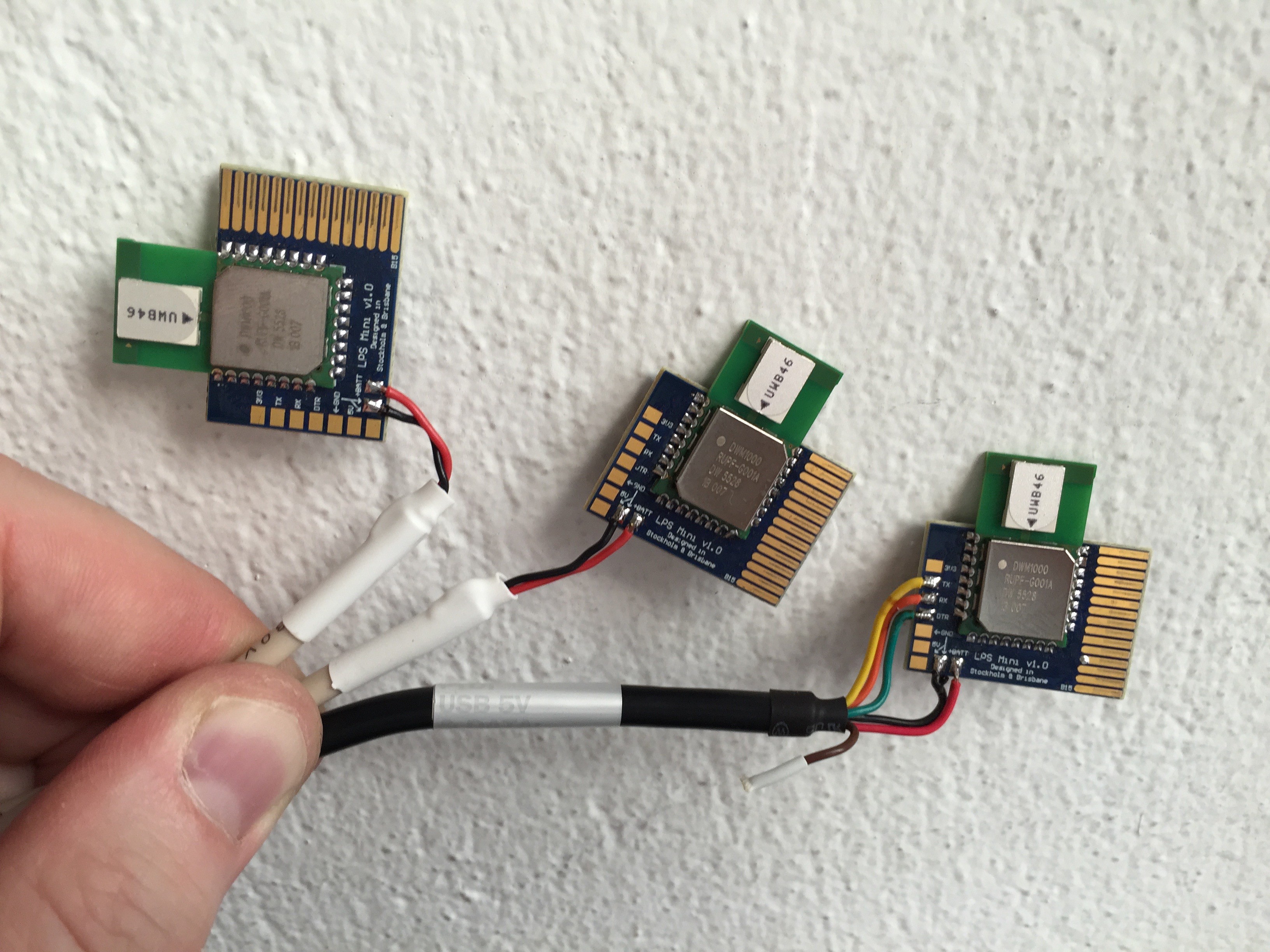
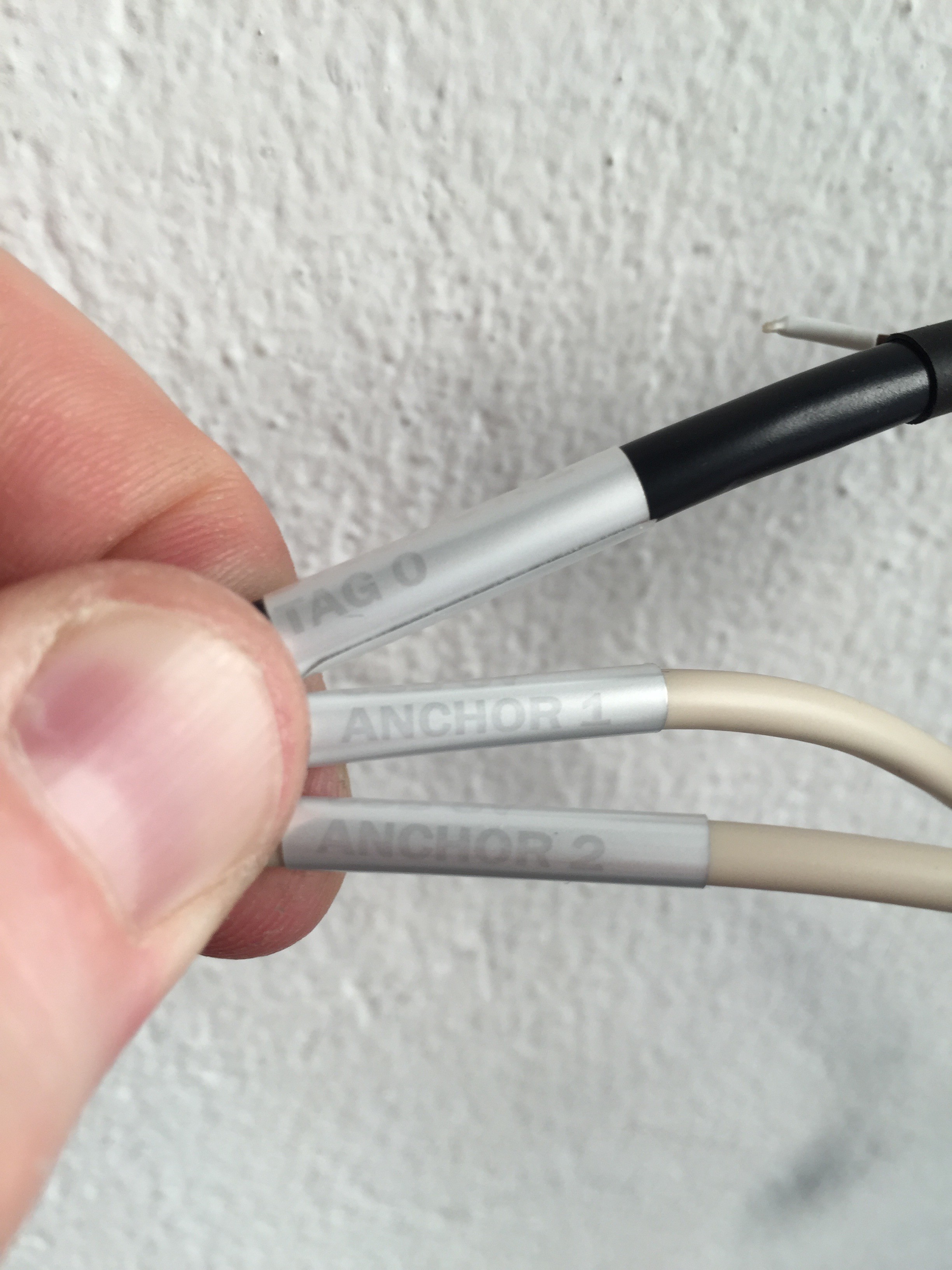
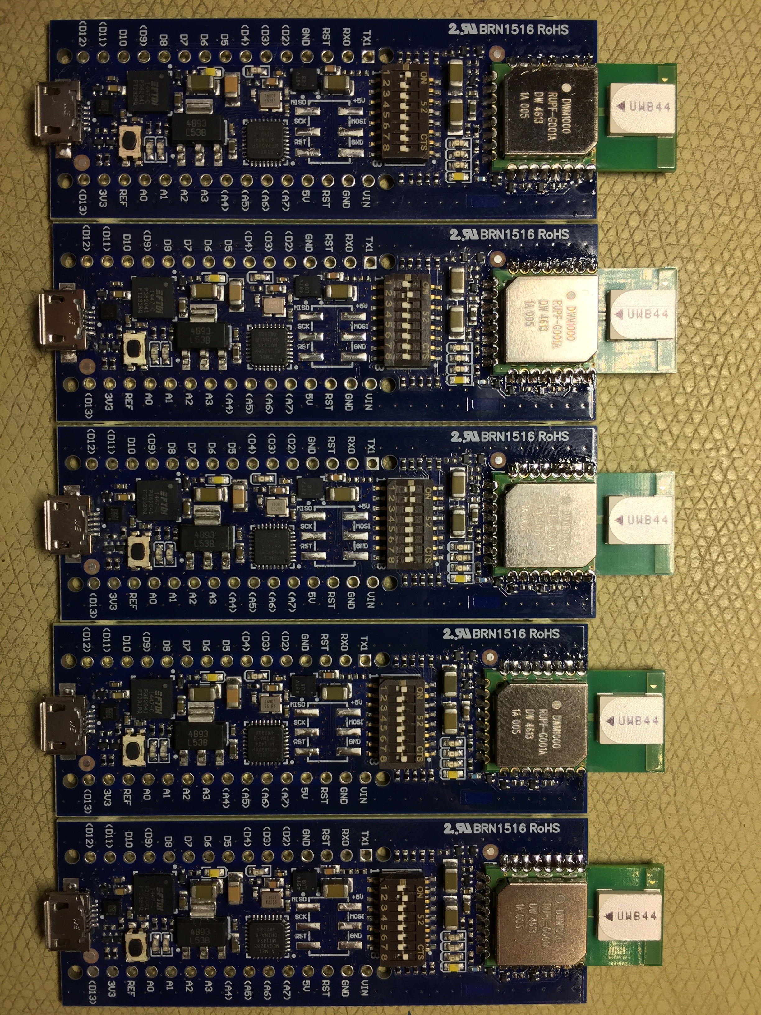
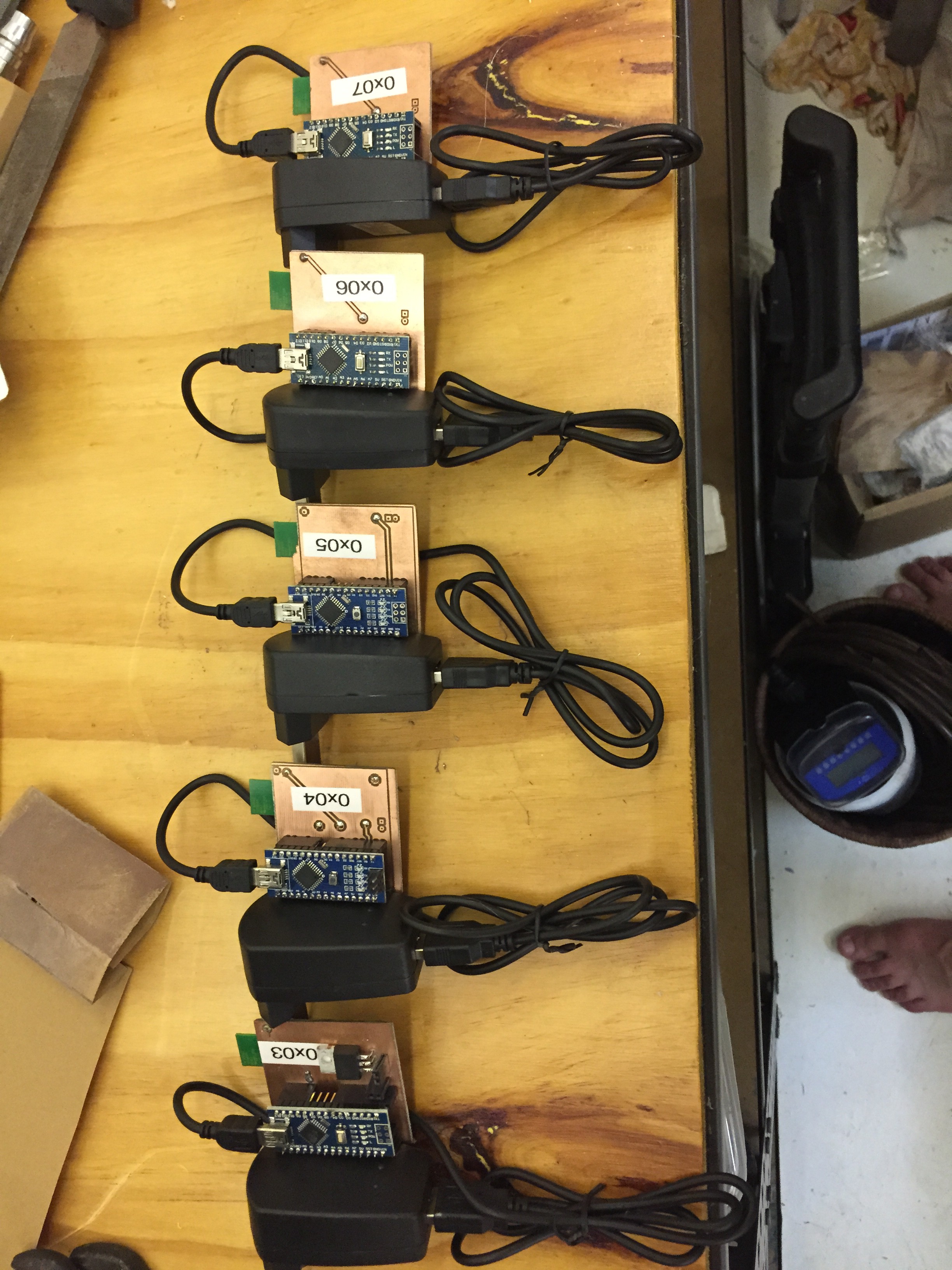
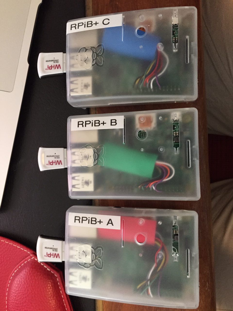
08/15/2015 at 22:14 • 0 commentsThree LPS Mini have been sent for evaluation to The 2015 Hackaday Prize! Hope they will arrive in time!
One is preconfigured as tag, the other two as anchors. Notice that the rightmost board (tag) except for USB 5V also got its UART connected to a FTDI cable. Otherwise hard to see the measured distances. The two anchors do not need to talk much, they are happy as long as they get power.![]()
![]()
-
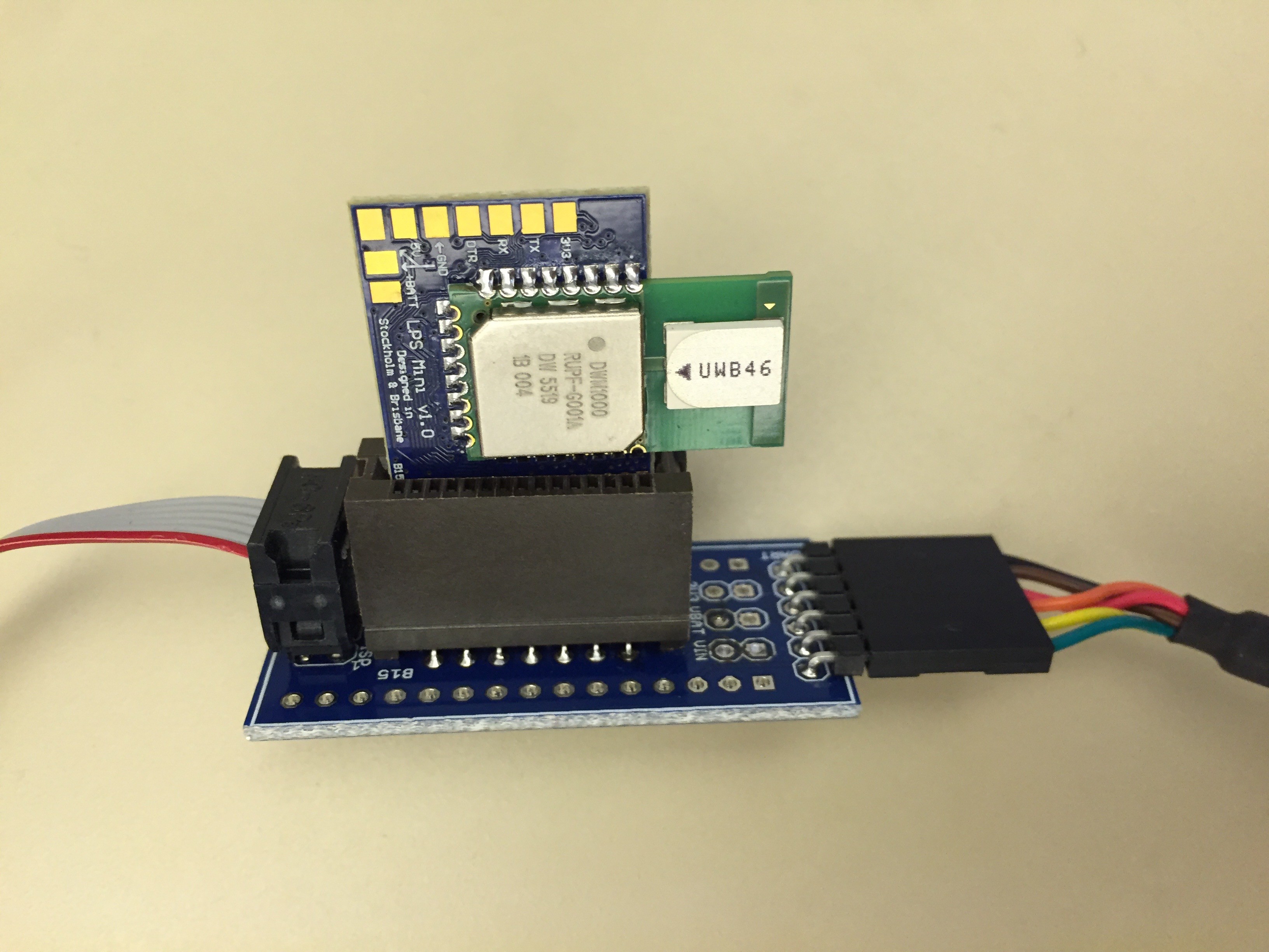
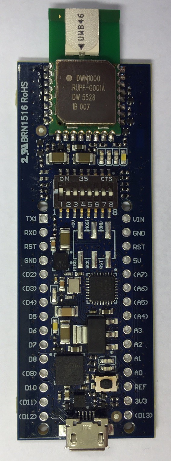
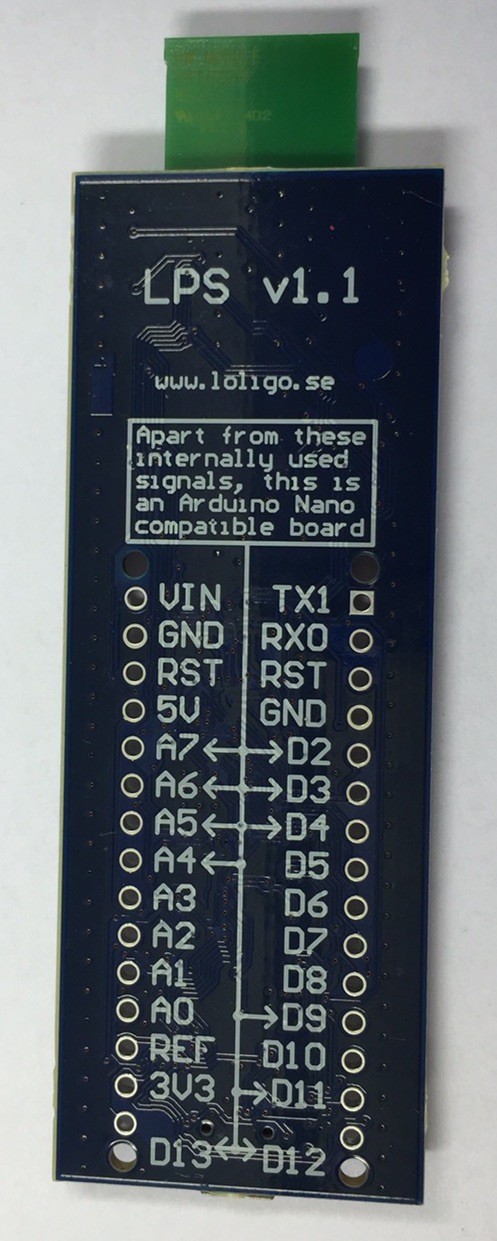
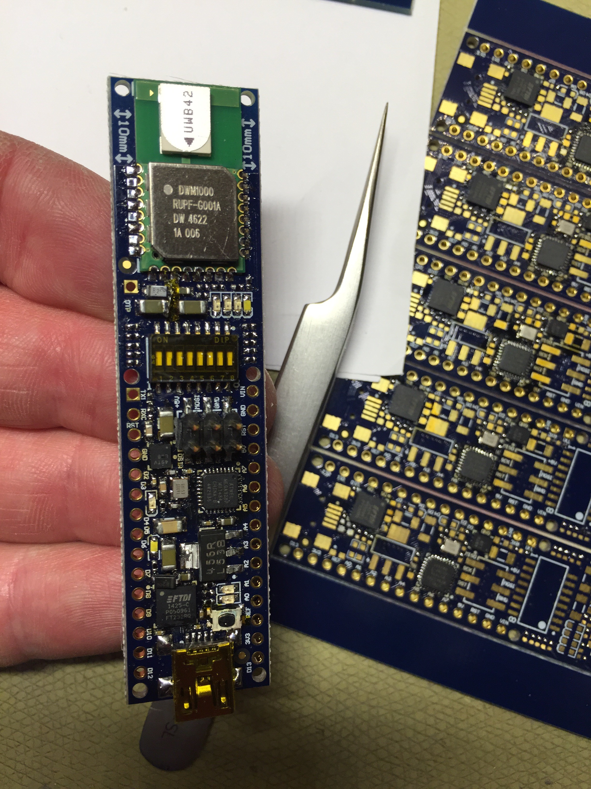
LPS Mini Adaptor
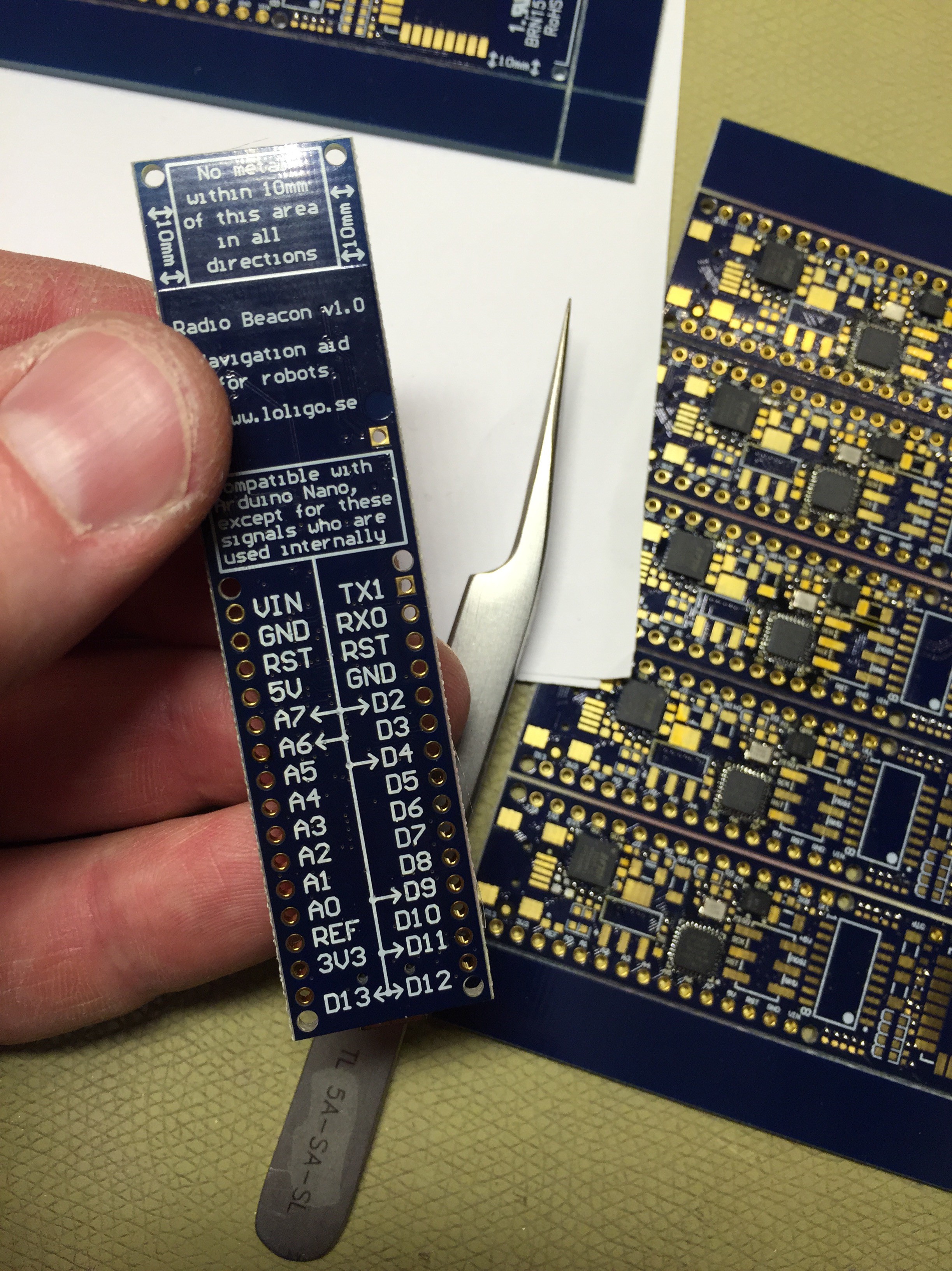
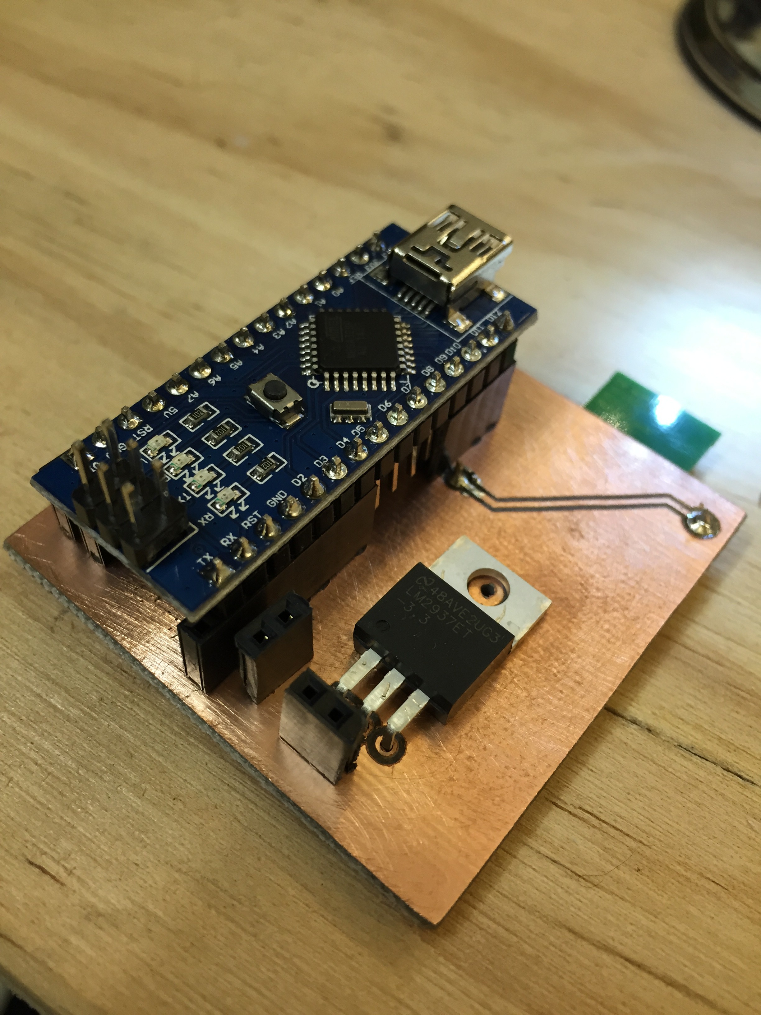
08/15/2015 at 21:53 • 0 commentsWe have made an adaptor for LPS Mini to give very easy access to all I/O, UART, ISP and power pins. The adaptor act as a bridge between TE Connectivity 5650712-1 (holds LPS Mini) and the standard Arduino Nano footprint. In most cases the adaptor is of no use except during test and debug. If all I/O is needed on a permanent basis, LPS might be a better choice than LPS Mini. The UART connector mates with FTDI USB TTL Serial Cable TTL-232R-3V3. The ISP connector mates with the standard AVR ISP 6-pin header.
![]()
-
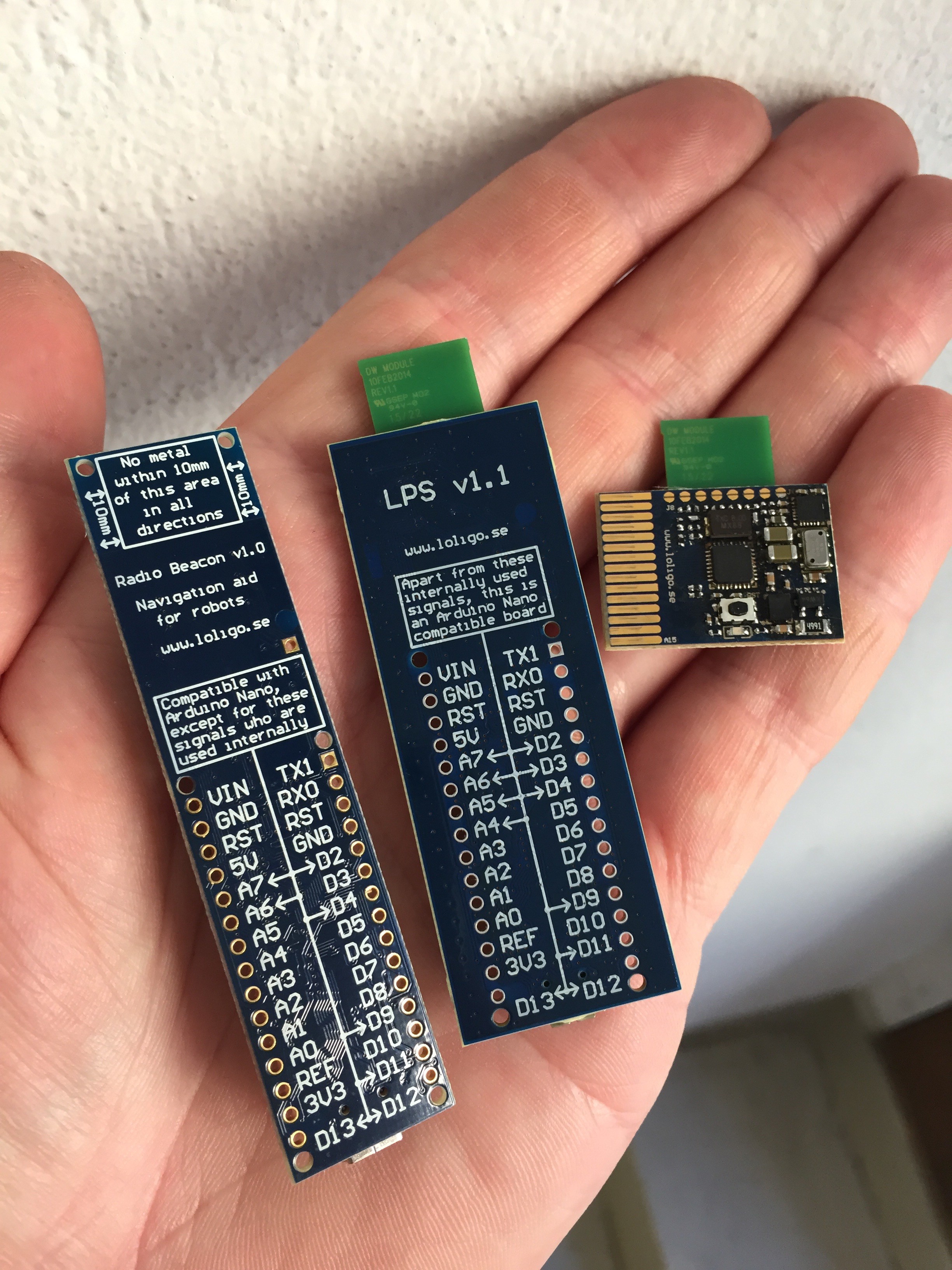
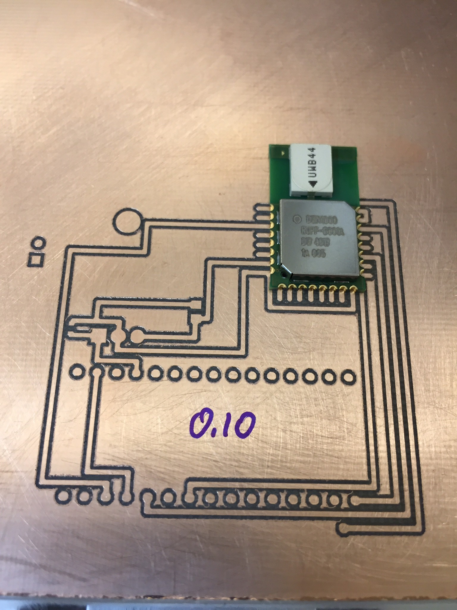
RadioBeacon v1.0 --> LPS v1.1 --> LPS Mini v1.0
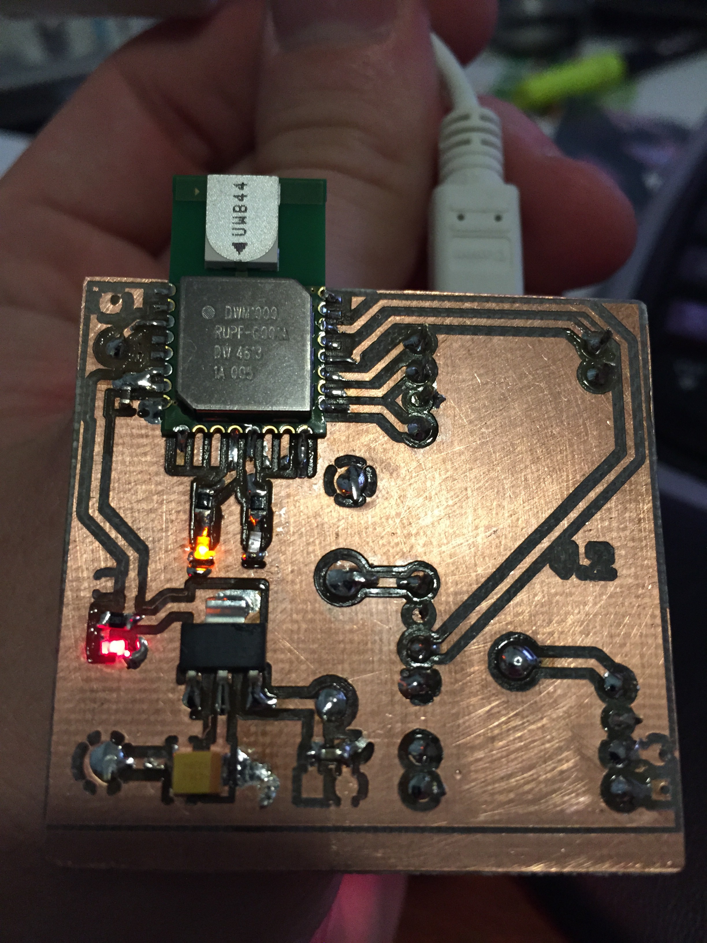
08/15/2015 at 21:47 • 0 commentsBy stripping down LPS v1.1 to a minimum, adding more advanced sensors (accelerometer, gyro, magnetometer and altimeter instead of just an accelerometer) and a LiPo charger, LPS Mini was born! It is hard making a much smaller board without compromising antenna performance. A nice little feature is that the entire board fits in a board edge connector making it possible to access all the I/O present on LPS v1.1 and ordinary Arduino Nano!
Schematic, assembly drawing and BOM:
http://www.loligo.se/navigation/LPS_mini_v1.0_150423.pdf
PCB animation:
http://www.loligo.se/navigation/LPS_mini_v1.0.WMV
Step by step transformation from LPS to LPS Mini:
http://www.loligo.se/LPS_mini/
The two pictures below depict the development steps from RadioBeacon v1.0 via LPS v1.1 to LPS Mini v1.0:
![]()
With help of the sensors in LPS Mini, inertial navigation can be done to improve performance. But again, the processing power of ATmega328P is not enough to do that job all by itself. Data must be sent either via UART/I2C or radio (piggyback data on measurement data packages) to an external CPU to do triangulation etc. In our case we use Raspberry Pi for all superior tasks and it works very well! An added benefit is the ability to do firmware upgrades from Raspberry Pi using the LPS boot loader.![]()
LPS and LPS Mini are compatible. LPS boards can use LPS Mini as anchor/tag and the other way around. Except a different set of sensors the main difference is that LPS use 5V I/O level and runs at 16 MHz, while LPS Mini got 3.3V I/O and runs at 8 MHz.
-
Thermal drift, crosstalk and other problems
08/15/2015 at 20:08 • 0 commentsWe have had our prototype boards up and running since February 2015. During this time we have noticed a few problems, or let us call them features:
- Thermal drift: DWM1000 does not have a TCXO. Depending on surrounding temperature and update rate (i.e. self heating due to radio usage), the measured distance can drift 3-5 cm before thermal equilibrium has been reached. This process can be as slow as half an hour or more.
- Crosstalk: This is a problem purely due to our own way of handling multiple tags. If tags get out of sync they will cause crosstalk with a random measurement error as result. Our initial remedy was taking a median value from several measurements and hope for the best. After introducing strict time alternation between tags the problem disappeared.
- Reflections: DWM1000 can not be mounted in contact with a wall. The reflection will be so close to the desired LOS-signal that DWM1000 can not distinguish between the two. Reported distance will thus randomly jump between two distinct values.
- Bootloader: If using optiboot everything is just fine. In other cases we have encountered problems with the watchdog not barking properly.
-
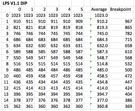
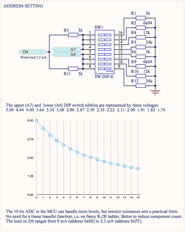
Analog DIP nibble values
08/15/2015 at 17:00 • 0 commentsGood old Ohm's law is still valid! This is how the analog DIP nibble values turned out in reality (ADC readings taken from six boards):
![]()
Very consistent and not far from the values predicted by theory :-)
-
LPS
08/15/2015 at 16:45 • 2 commentsAfter some thought the project name RadioBeacon was dumped for Local Positioning System - LPS. Lessons learned with RadioBeacon v1.0 was implemented in LPS v1.1:
- No PCB under the DWM1000 antenna.
- Need for a slightly wider PCB to get better antenna performance.
- Need for level shift between the 5V I/O in use by ATmega328P and the 3.3V preferred by DWM1000.
- Added an accelerometer to enable deep sleep modes for tags not being in motion to save power.
The updated schematic, assembly drawing and BOM:
http://www.loligo.se/navigation/LPS_v1.1_150409.pdf
PCB animation:
http://www.loligo.se/navigation/LPS_v1.1.WMV![]()
![]()
![]()
-
RadioBeacon
08/15/2015 at 16:27 • 0 commentsThe main problem in all projects: determine a project name. The first prototype PCB did not have a silkscreen, so no one could notice the lack of a proper name. Now it was time for a factory made PCB. Its silkscreen layer in our CAD program was screaming for describing texts in general and a project name in particular. After some thought we came up with RadioBeacon. Its schematic, assembly drawing and BOM can be found here: http://www.loligo.se/navigation/RadioBeacon_150308.pdf
PCB Animation: http://www.loligo.se/navigation/RadioBeacon_150308.WMV
RadioBeacon v1.0 is not much more than an Arduino Nano clone with the addition of DWM1000 and a DIP switch for address setting and configuration. In order to save valuable I/O pins the DIP switch is arranged in two nibbles to be read out as two analog voltages, saving 6 digital I/O.
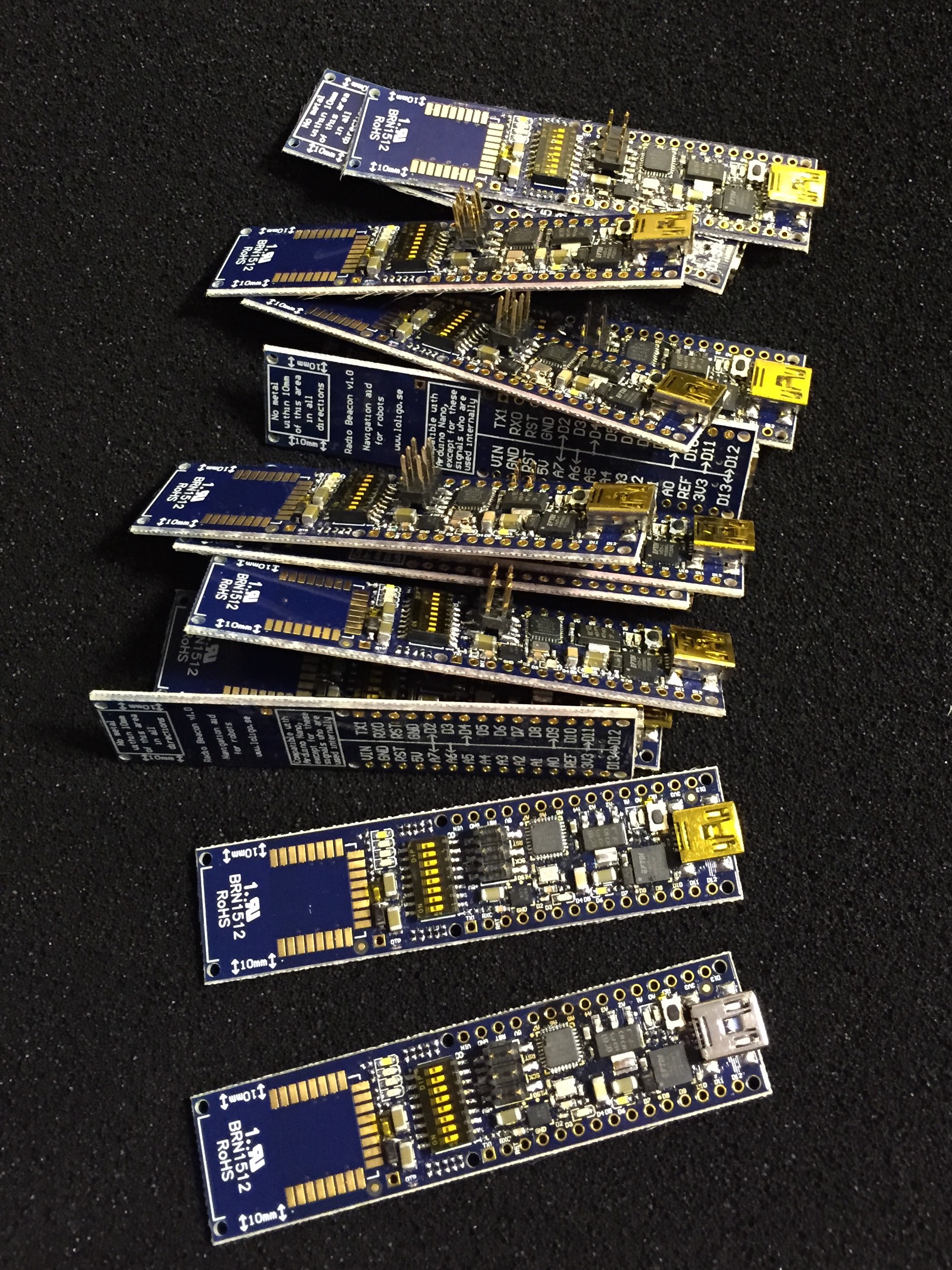
![]() This is how the hand assembled RadioBeacon v1.0 boards turned out:
This is how the hand assembled RadioBeacon v1.0 boards turned out:![]()
![]()
![]()
After running them for a while we noticed that DWM1000 got warmer than expected. That is how we figured out it does not like 5V I/O... (we misinterpreted the data sheets a bit). Nonetheless, RadioBeacon 1.0 worked well and provided us with many important lessons.
-
Arduino lib + initial long term tests
08/15/2015 at 15:18 • 0 commentsThe development boards from Decawave use a STM32F105 ARM Cortex M3 processor. The supplied source code use floating point math and other fancy things not easily performed by a small 8 bit MCU (in our case: ATmega328P). In order to squeeze it all in we had to rewrite large portions of the code and make some simplifications, but without compromising performance. Now we got an Arduino lib to be used with our little board! There is still room for optimisation, but it is good enough for now. It will be released when it has been tidied up a bit. We are currently implementing the wisdom of Donald Knuth: "Premature optimization is the root of all evil" :-)
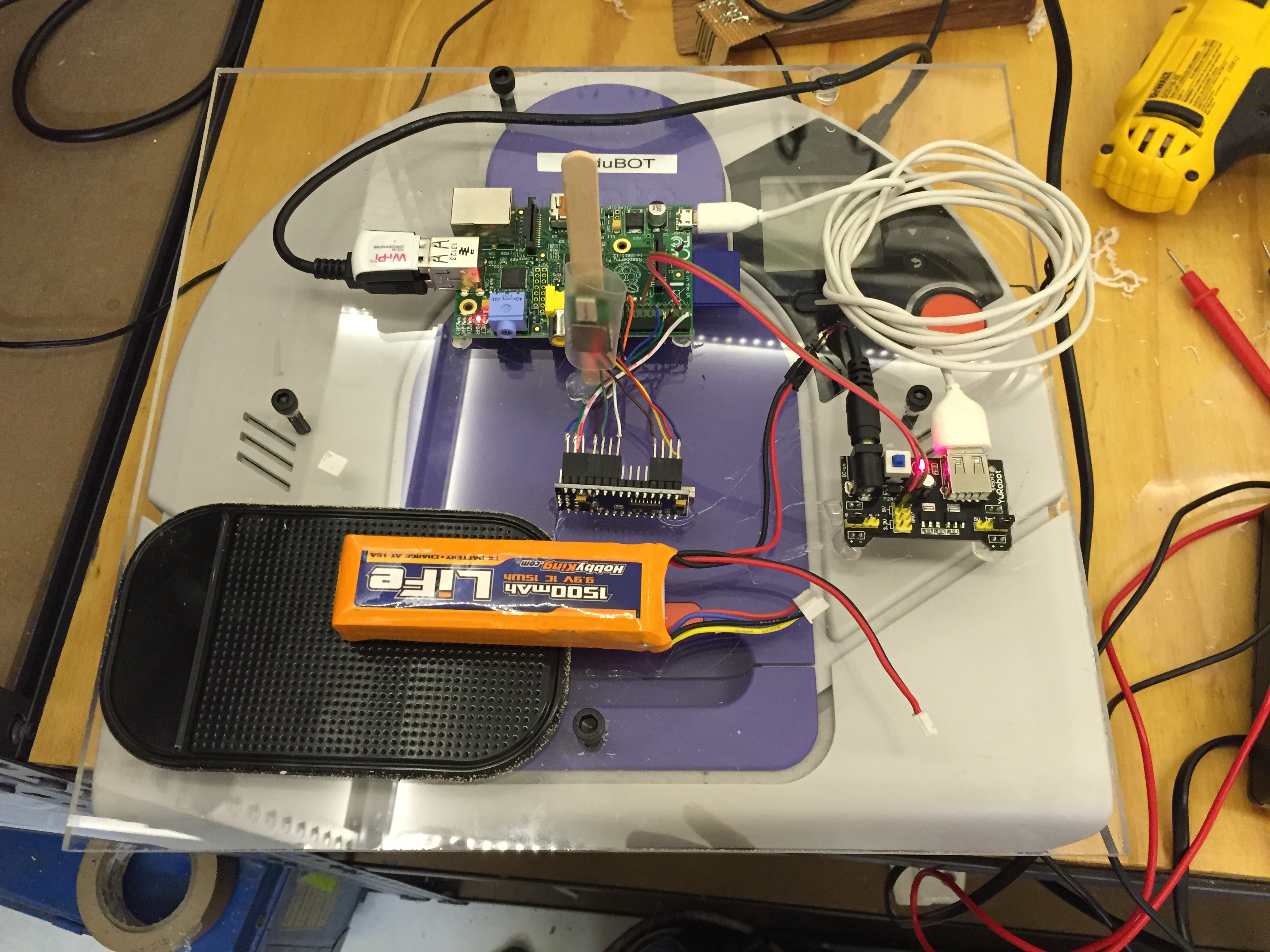
With our first set of stable hardware prototypes it has been possible to perform long term tests without the problem of hardware crashes. Our tag asks around among all anchors it can see and reports the measured values to an external MCU (e.g. Raspberry Pi), where localisation is done. Our board is thus to be considered a navigation sensor, not a stand-alone navigator.
![]()
-
First prototype
08/15/2015 at 14:47 • 1 commentOur need is a navigation aid for mobile robots. It does not hurt if the design is so simple that others can use it without much effort. Making an Arduino compatible board was thus the obvious choice. The first attempt was more of a shield though, just to get us going. It was also a perfect excuse to try out a little cute CNC router to make PCB prototypes.
![]()
![]()
![]()
-
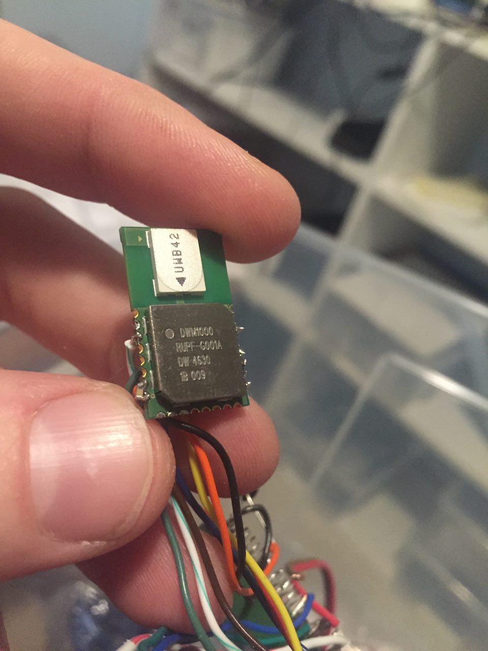
Quick and dirty test with Raspberry Pi
08/15/2015 at 13:12 • 0 commentsTo quickly get started with DWM1000 we soldered them in directly to Raspberry Pi using thin wires. This is a bad idea for at least three reasons:
- No proper ground plane under DWM1000 affecting the antenna performance.
- No proper decoupling.
- Raspberry Pi do not handle interrupts very well, so we had to poll the interrupt pin --> slow performance.
![]()
![]()
The result was a very unstable setup, but good enough to get us acquainted with DWM1000. It was also the first time we could setup a moving tag (on a robot vacuum cleaner) and several anchors to do triangulation![]()
LPS Mini
Arduino compatible indoor navigation system with small form factor.