-
Polar Camera Prototype Improvements
08/17/2015 at 21:21 • 0 commentsThere are a number of improvements that can be done, and here I will list the main ones I will be focusing on in the next few weeks.
1. Removing the slip rings completely as they produce noise and do not work well at high rpm as well as produce vibrations. Instead replace them with induction coils (this is also known as a rotary transformer) and thus wirelessly transmit the information from the camera to the processor. The power will remain on a slip ring, however this will be simplistic and unrestrictive.
2. Modifying the slip ring so that instead of wires it uses copper spring loaded pads which dynamically adjust the pressure on the slip ring minimising friction and thus motor current required reducing the vibration.
3. Modify the entire build to no longer move the sensor circulary, but linearly thus removing the blind spot in the centre of the circle. This allows us to also operate without sliprings as well as require no interpolation, but also results in a rectangular image. However oscillatory vibrations will need to be accounted for at the resonant frequencies.
This project log will be updated with more info as soon as it is available.
-
Polar Camera Prototype #1
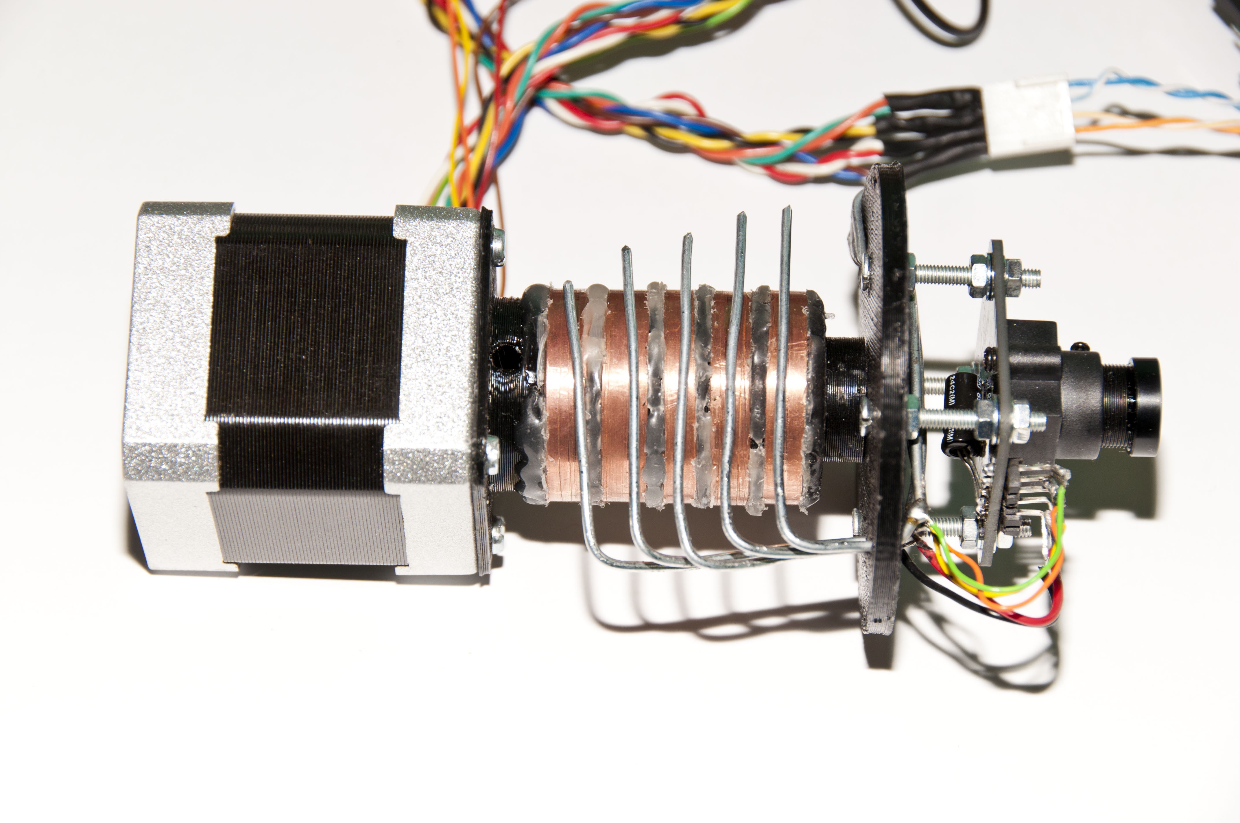
08/17/2015 at 21:19 • 1 commentThe initial prototype uses an STM32F072 Discovery board, a stepper motor, a 3D printed, 5 contact slip ring with a bore down the middle and the LSA. The prototype works so-and-so; the excessive vibrations and unreliable slip ring operation make the obtained results hard to reproduce. We send the data from the STM32 to the computer using a simple UART transceiver and implement a serial interface in MATLAB to capture the results. I will have full technical details of the setup including scope waveforms, etc.
![]()
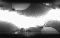
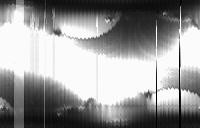
Every column in the image below represents a scanned line at a single step of a 200-step stepper motor. The sensor has 128 pixels, thus the 'image' has 200x128 pixels. The line at the bottom is a speck of dust on the sensor.
![]()
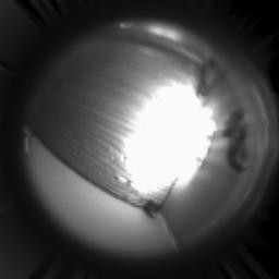
This is the magic part. If we run this image through the MATLAB scattered interpolation sequence described in Project Log 2 we obtain the image below. Note that the fisheye effect is more due to the stock lens used on the sensor rather than the algorithm itself.
![]()
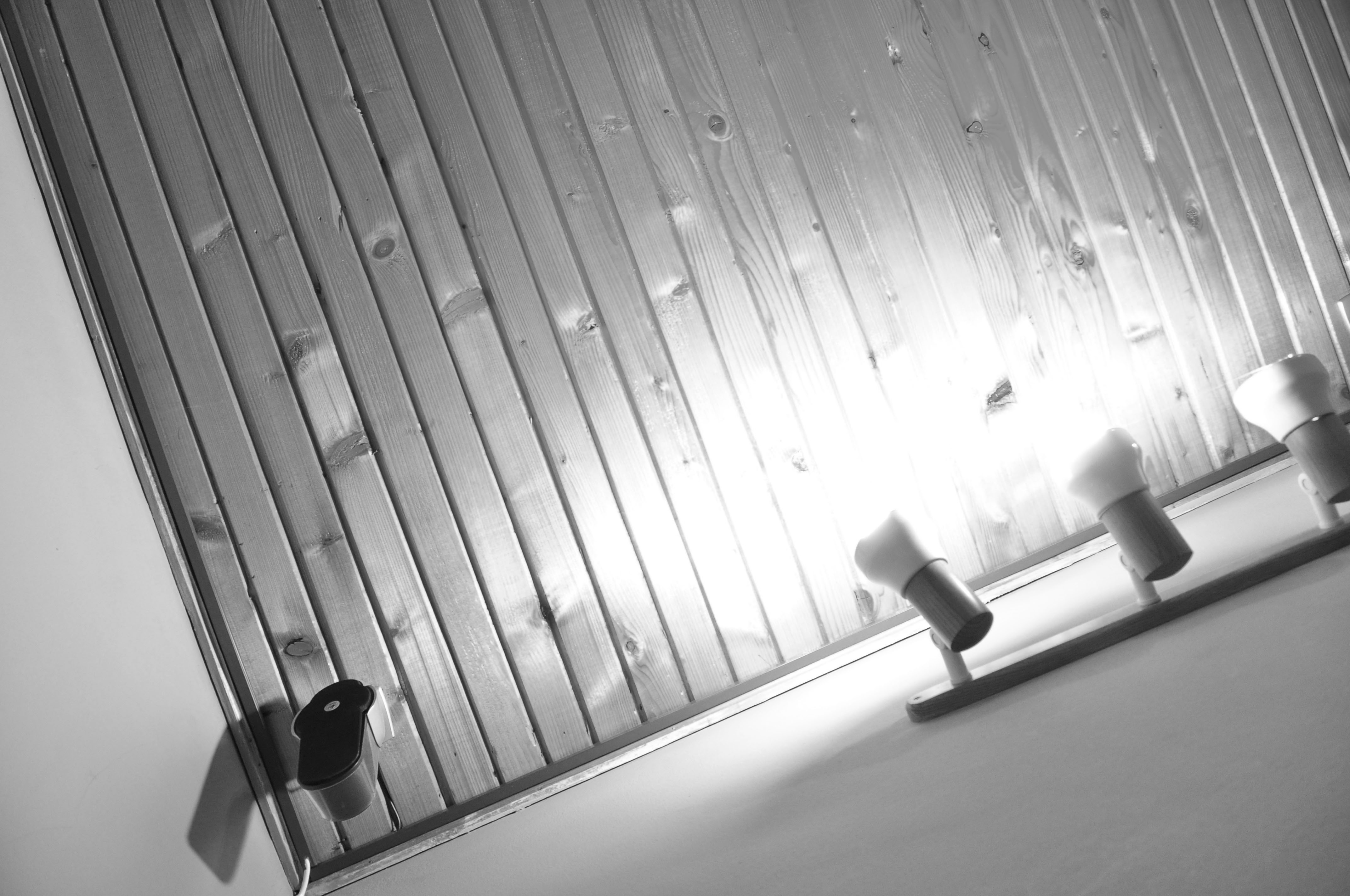
With a conventional DSLR camera, this is the image taken from *approximately* the same location, but with a much less wide angle:
Now let's take a look at the same picture captured again, after the motor has been dormant for a while and the motor current slightly increased so it doesn't occasionally stall.
![]()
The vibrations are very apparent from the periodic nature of the distortions. The uncleaned dust particle on the bottom half of the image confirms that vibrations are indeed the culprit since it's jumping from pixel to pixel for different angles. Furthermore there are some 'blanking' lines where either the slip-ring contact was imperfect or the vibrations caused bad things to happen.
Studying this image in closer detail, we discover that some areas have more vibration induced distortions than others which leads us to believe that the centre of vibrations is not centred.
-
Polar Camera Simulations
08/17/2015 at 20:57 • 0 commentsThe next natural step is to simulate the concept somehow. I chose to do this in MATLAB, and while it is neither open-source nor free (even though I, as a student, have free, unrestricted access to it from my university) you can likely do everything I did in MATLAB in GNU Octave, which is open-source.
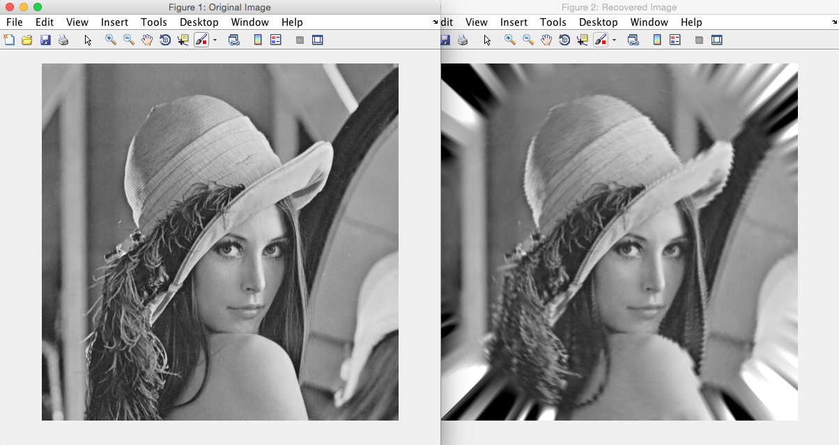
The MATLAB simulation takes an input image and creates a scattered data interpolant of it. It then samples this image at non-discrete points (using the interpolant) that correspond to the radial sampling pattern of the sensor. It can also simulate sensor concentricity mismatch, the formula for which can be derived using Pythagoras' theorem (I'll have more detail on this soon). The radial samples are then used to create another interpolant from which the final image will be reconstructed.
The simulation was set up in such a way that a number of parameters can be changed with ease; sensor pixel count, samples around the circle, and final desired image size.
Below is a picture showing the original image (on the left) passed to the simulation and the reconstructed image (on the right) obtained at the end of the simulation. Notice how high frequency details (i.e. areas of high contrast or thin details) are lost further out from the centre due to the nature of radial sampling. The original image is the same size as the reconstructed image at 512x512 pixels, and the simulation was done using a sensor 128 pixels long, with 200 samples around the circle.
![]() A video simulation will be shown soon.
A video simulation will be shown soon. -
Polar Camera Concept
08/17/2015 at 20:42 • 0 commentsThe first experiment will be to create a polar camera. The creation of the polar camera came due to the high cost of high speed cameras. Most high speed cameras today, such as the Phantom, cost up to and over $100000. Further to cost, I have always wanted an affordable camera that also has a high frame rate and decent quality.
The polar camera deviates from the standard camera that shines light onto a rectangular sensor and refreshes the sensor rapidly to capture high FPS video. The polar camera functions by rotating a linear sensor and capturing the projected light field at certain intervals.
The advantages this brings to high speed video comes primarily from the much reduced cost of the product, however it should also solve problems that have plagued the high speed industry for years. Linear sensors have much larger pixels, thus having the ability to capture light much quicker and efficiently. This allows the camera operating at high speed to no longer require intense lights to illuminate the field. This makes extremely high speed videos much more pleasant to watch. However we need to figure out though whether this increase in active area combined with the far more rapid, multiple exposures needed to obtain just a single image work together.
Furthermore the camera is able to operate at much higher frame rates, as the frame rate is limited by the rotation of the sensor, not by its refresh rate (linear sensors refresh rate is no trouble e.g. up to 53k lines/sec for an el-cheapo TSL1401CL sensor at 128 pixels.
As we do not live in a perfect world, there are also disadvantages. Circular photos are produced as opposed to the standard rectangular photos. This however can be remedied by cropping a large circular photo into a rectangle. Furthermore, due to the mechanical qualities of this camera, there is an aspect of wear and tear in the spinning parts.
A detailed diagram of how this will work will be up soon.
 A video simulation will be shown soon.