-
STL files released
04/30/2014 at 08:53 • 0 commentsAlthough some parts may need improvement (we're revising the pod axial bearings now) the stl files have been made available to the public.
Feel free to get a copy of these files and edit them to you liking. Be sure to get in touch if you have any suggestions / ideas.
Have fun!
https://drive.google.com/folderview?id=0B5pLRClac1i-Tmp4dW5wMGdnVFE&usp=sharing
-
To Every Rover (Turn! Turn! Turn!)
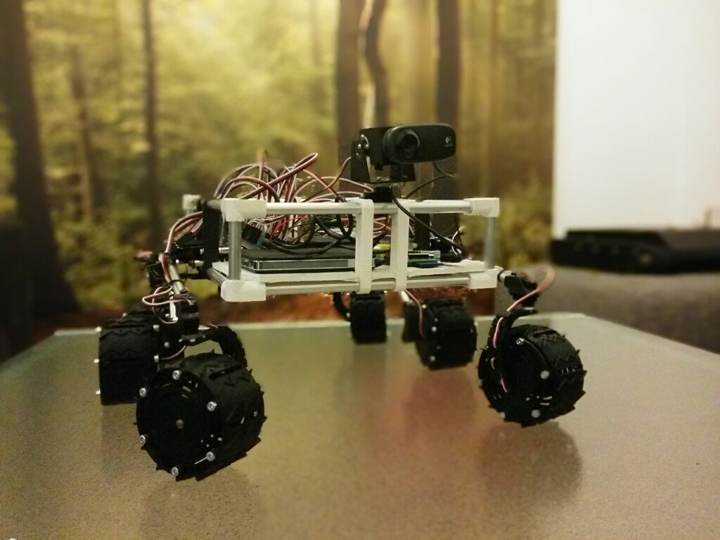
04/20/2014 at 09:55 • 0 commentsThe software running on the Raspberry Pi is responsible for driving the Rover around. But with 10 distinct servo's controlling the wheels we need some smarts to drive around.
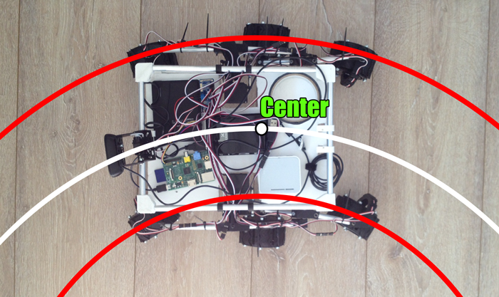
The software takes two parameters as input: A driving speed and a turning radius. All the wheels are in different positions so they all need to be driving at different angles and speeds to prevent the wheels from slipping. Just like with a car, the wheels on the inside track need to drive more slowly than those on the outside track.
To solve this the wheels are angled to drive along imaginary circles. This makes the rover drive gracefully around every obstacle.
![]()
In our test drives we found out that the rover is capable of some very sharp cornering allowing the platform to navigate tight spaces with relative ease.
Next step: rotating in place.
-
Upgraded suspension and a new video
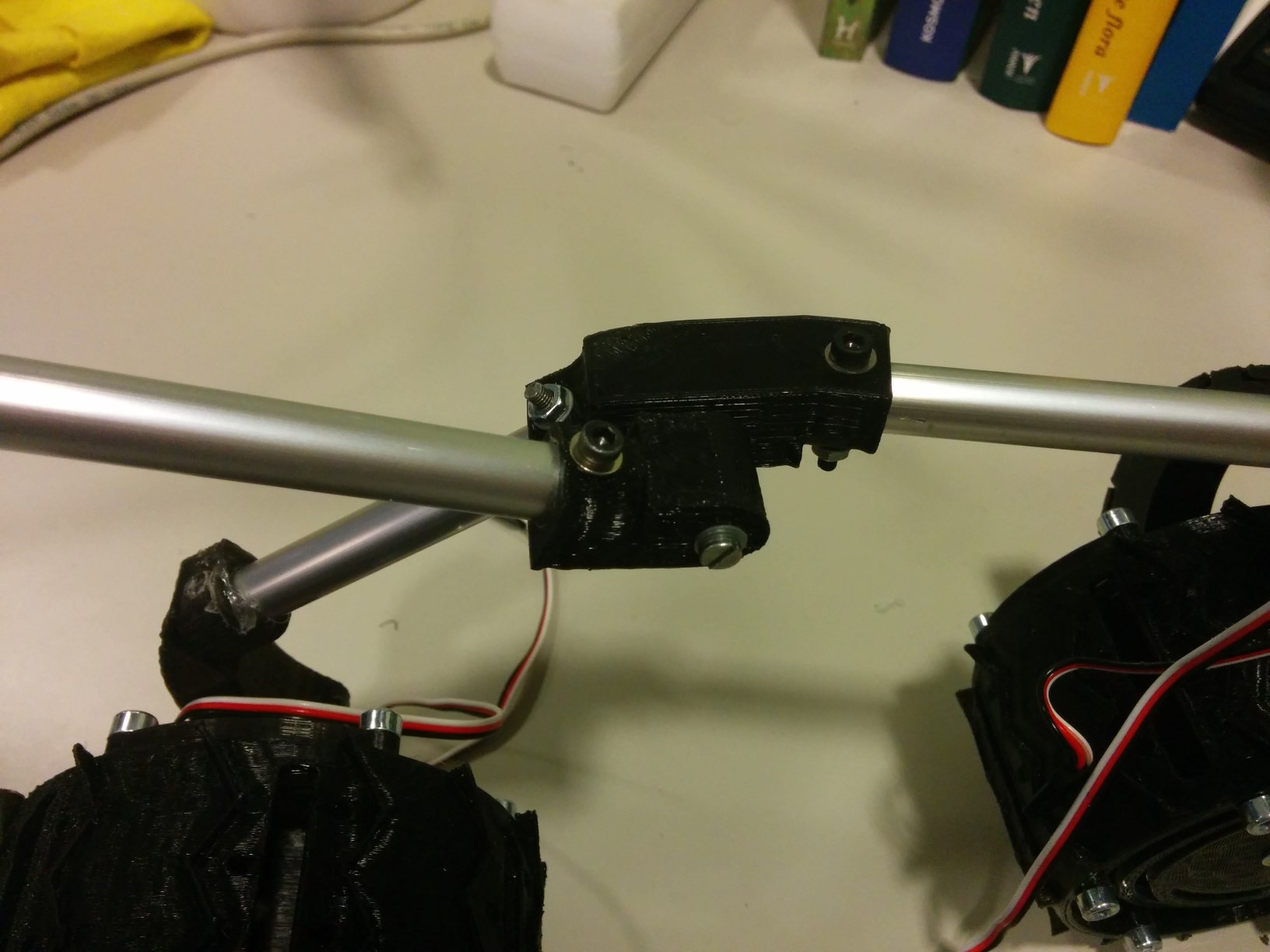
04/17/2014 at 20:43 • 2 commentsThe hotmelt in the joints gave way when we were driving around some. I took the opportunity to rework every joint. Here's a couple of pictures:
![]() The cross-bar is just there to keep it together for now.
The cross-bar is just there to keep it together for now.![]() Lower right is a little drilling guide I printed, makes drilling holes in the center of the tubes easier.
Lower right is a little drilling guide I printed, makes drilling holes in the center of the tubes easier.![]() Hope you're liking these close-ups
Hope you're liking these close-ups![]()
![]()
Let's see what obstacles it can conquer now!![]()
Thanks for all your skulls! We appreciate it.
Pauls log on the software is up and coming, he just seems to be even a bit busier than I am.
-
First steps!
04/10/2014 at 20:03 • 0 commentsThis video says it all. Next time Paul and Tom will do a little write up about the software side of things.
-
Everybody, rock your bogie right!
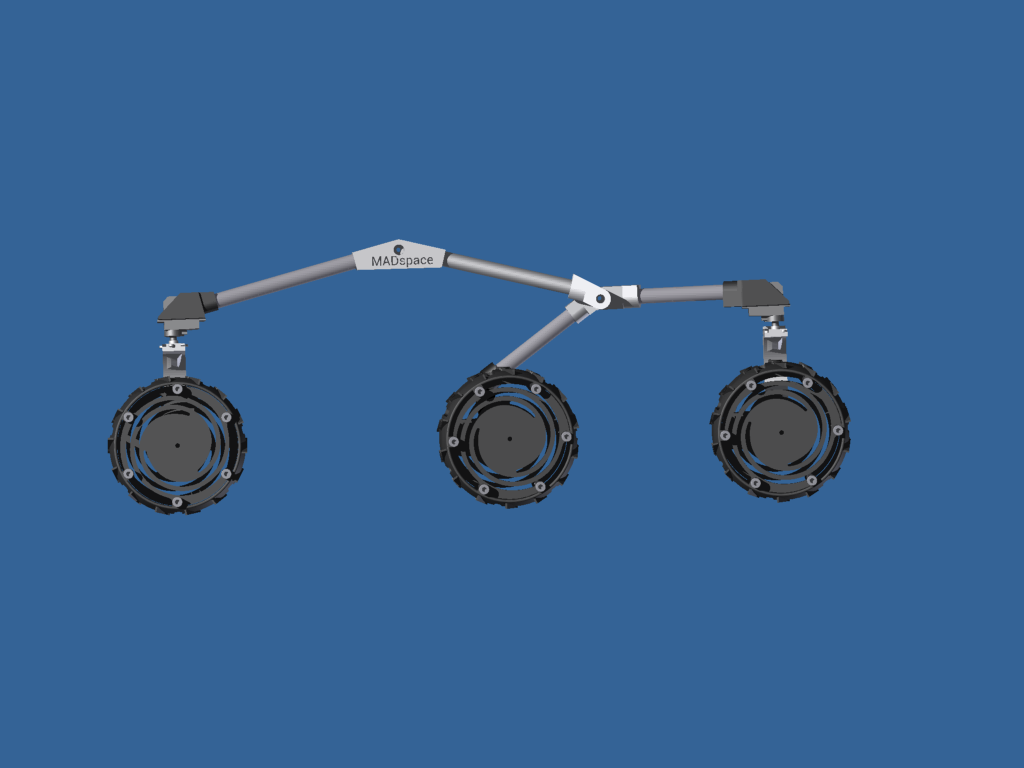
04/08/2014 at 22:28 • 0 commentsA render once told me a finished rocker bogie assembly should look something like this:
![]()
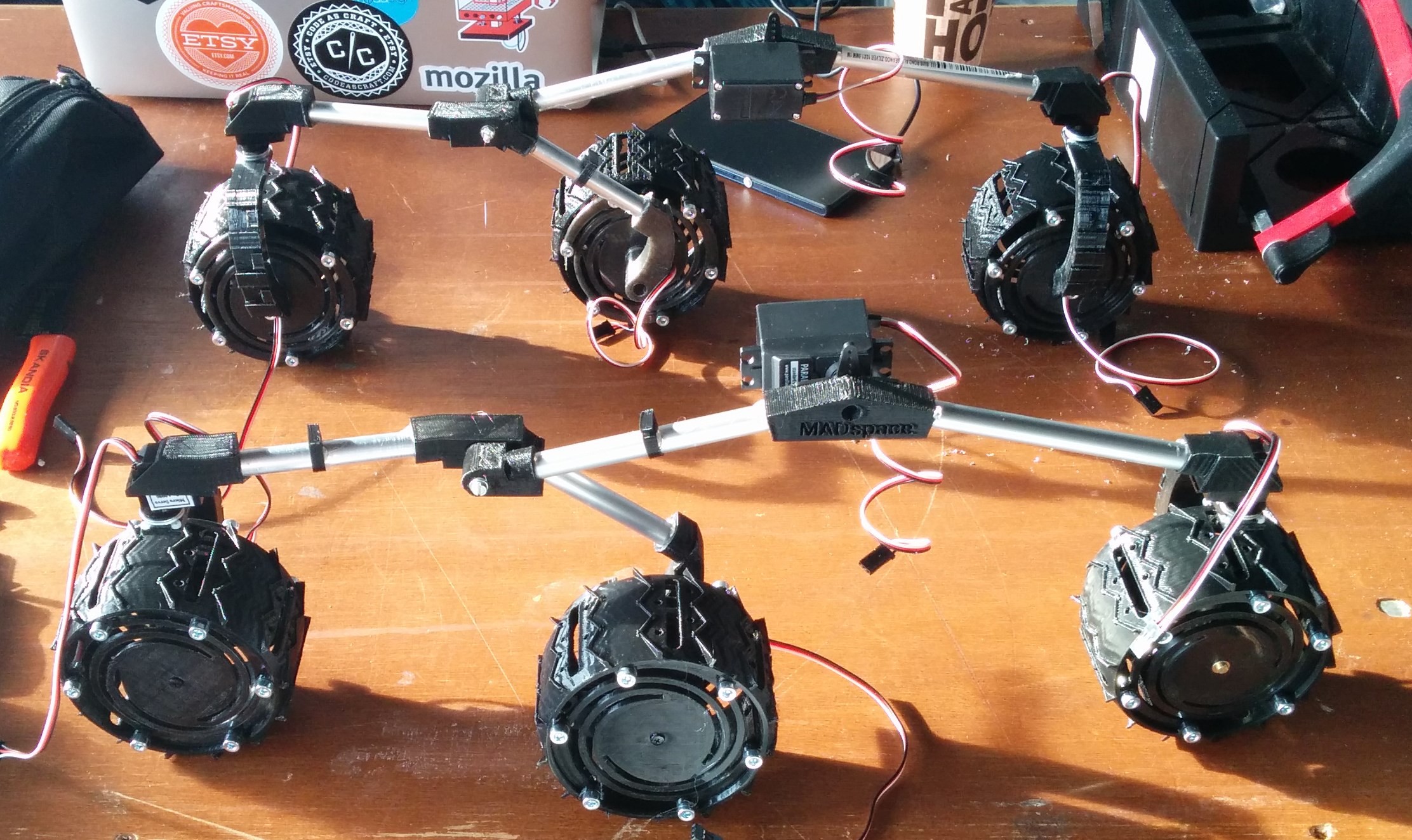
Good, now let's make two, and let one be a mirror image of the other
![]() Done! I just used a normal hacksaw to cut the aluminum tubes to size. They were glued in place with some hotmelt, they come off with some excessive twisting force if I ever have to re-position them.
Done! I just used a normal hacksaw to cut the aluminum tubes to size. They were glued in place with some hotmelt, they come off with some excessive twisting force if I ever have to re-position them. -
Tick tack toe, six in a row
04/08/2014 at 22:11 • 0 commentsAssembling some wheels eh? We need six, my cordless drill is working overtime drilling every hole ready for tapping thread. It's all M4 so just my trusty 3.2mm drill and me.
This is an inner hub, the big center hole fits a ball bearing.
![]()
Some wheels; we're printing them on low quality, this saves time. Doesn't have to be pretty!
![]()
Inside each wheel is one of these:
![]() Servo, bracket (it just snaps on), axle with bearing and whisbone. Notice how the wire feeds through the bearing.
Servo, bracket (it just snaps on), axle with bearing and whisbone. Notice how the wire feeds through the bearing.Wheels, assemble!
![]() So this took quite some time and patience. I cheated a bit and also assembled the steering servos to two of the wishbones, can you spot them?
So this took quite some time and patience. I cheated a bit and also assembled the steering servos to two of the wishbones, can you spot them? -
The body, The blood, The machine
04/08/2014 at 22:02 • 0 commentsMy body is ready! Being nothing more than the housing of most electronic components, I designed it fairly simply. Because the aluminum tube and lug design of the rocker-bogie worked quite well I decided to go with this setup as well.
To create the geometry i conjured up these 'corners'. Got some inspiration from k'nex:
![]() This one is labeled '1', There's also a '2', an exact mirror image.
This one is labeled '1', There's also a '2', an exact mirror image.Together with some other parts it makes up the rover's body:
![]() Next up: first real life assembly!
Next up: first real life assembly! -
Rocker bogie design done
04/08/2014 at 15:07 • 0 commentsAfter various iterations of most parts, a lot of wasted PLA plastic we can finally engrave V1.0 on all designs.
To determine the length and angle of all aluminium tubing I made this 2D drawing:
![]()
When this is fed into our 3D design we can make something like this:
![]() Awesome! Next up: the body.
Awesome! Next up: the body.
 Guus van der Sluijs
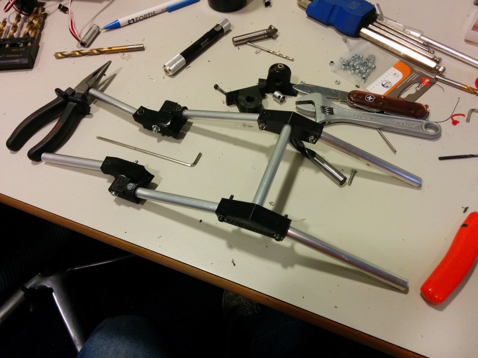 The cross-bar is just there to keep it together for now.
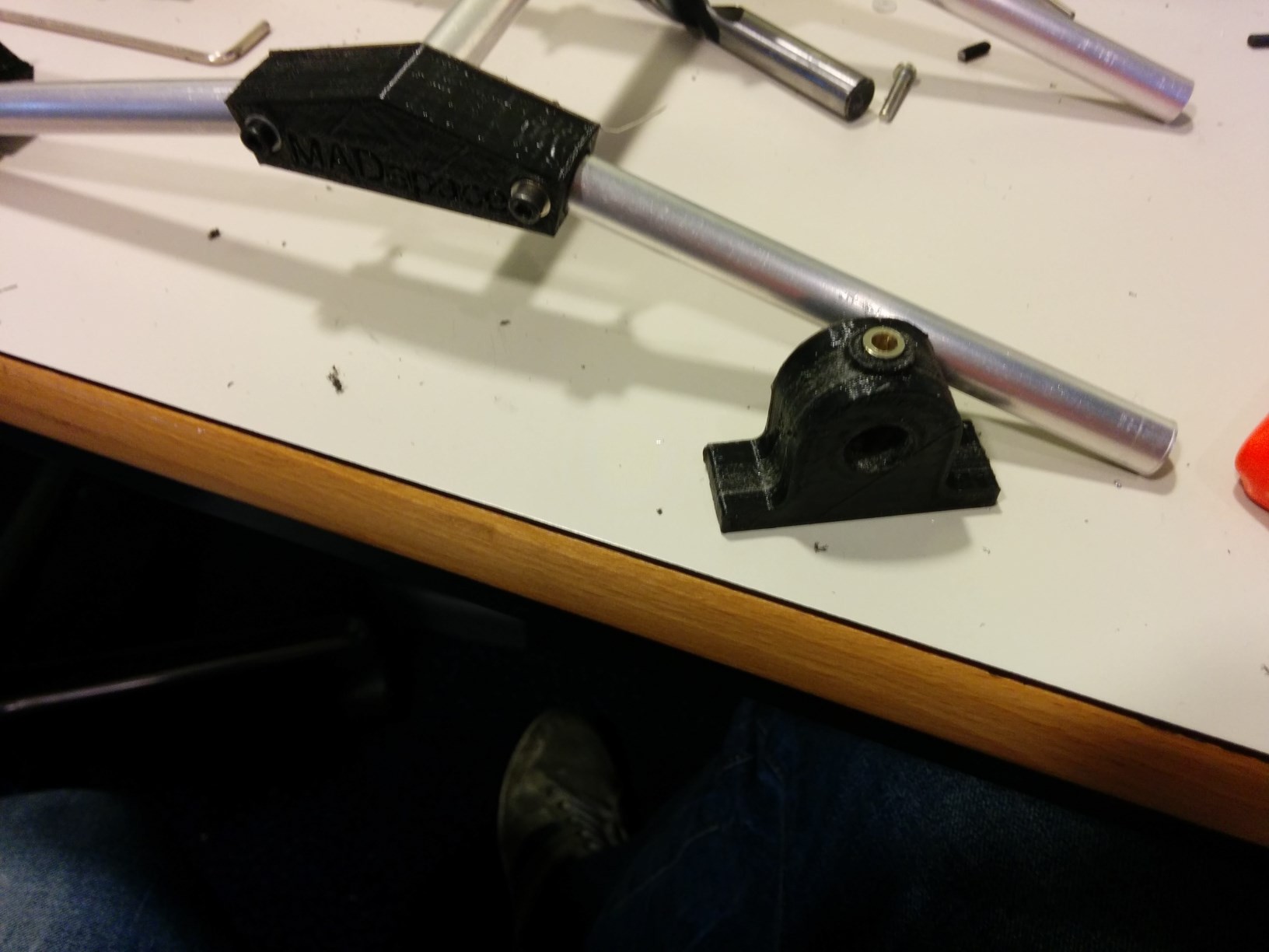 Lower right is a little drilling guide I printed, makes drilling holes in the center of the tubes easier.
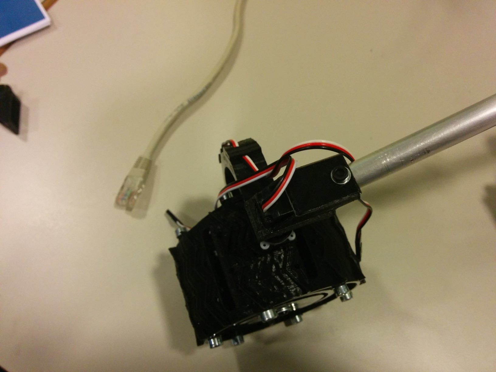 Hope you're liking these close-ups

 Done! I just used a normal hacksaw to cut the aluminum tubes to size. They were glued in place with some hotmelt, they come off with some excessive twisting force if I ever have to re-position them.
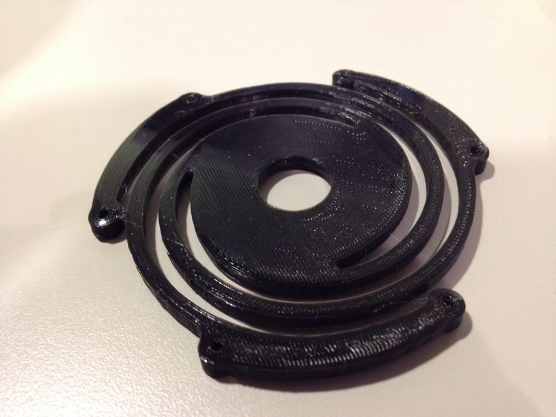
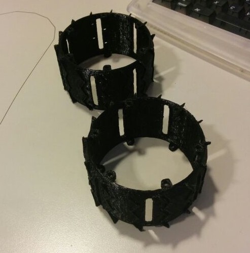
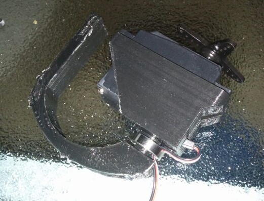 Servo, bracket (it just snaps on), axle with bearing and whisbone. Notice how the wire feeds through the bearing.
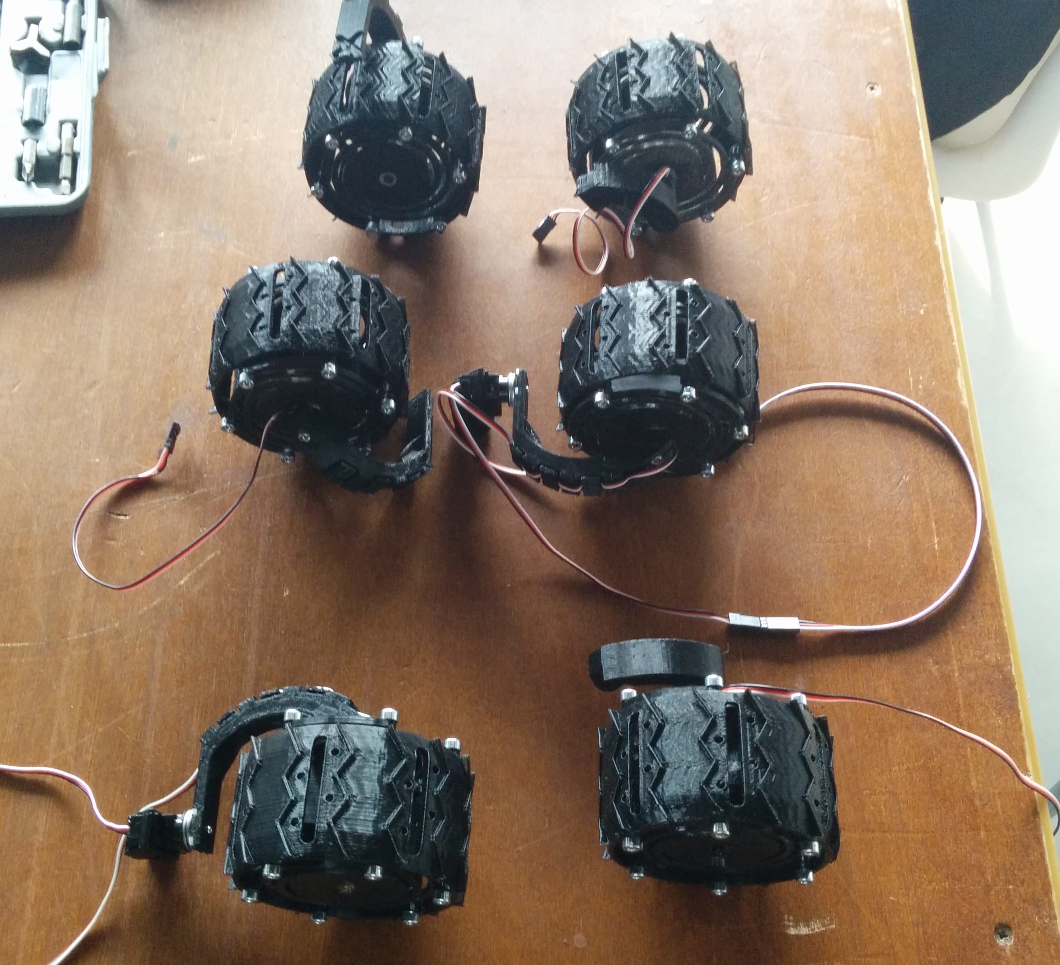 So this took quite some time and patience. I cheated a bit and also assembled the steering servos to two of the wishbones, can you spot them?
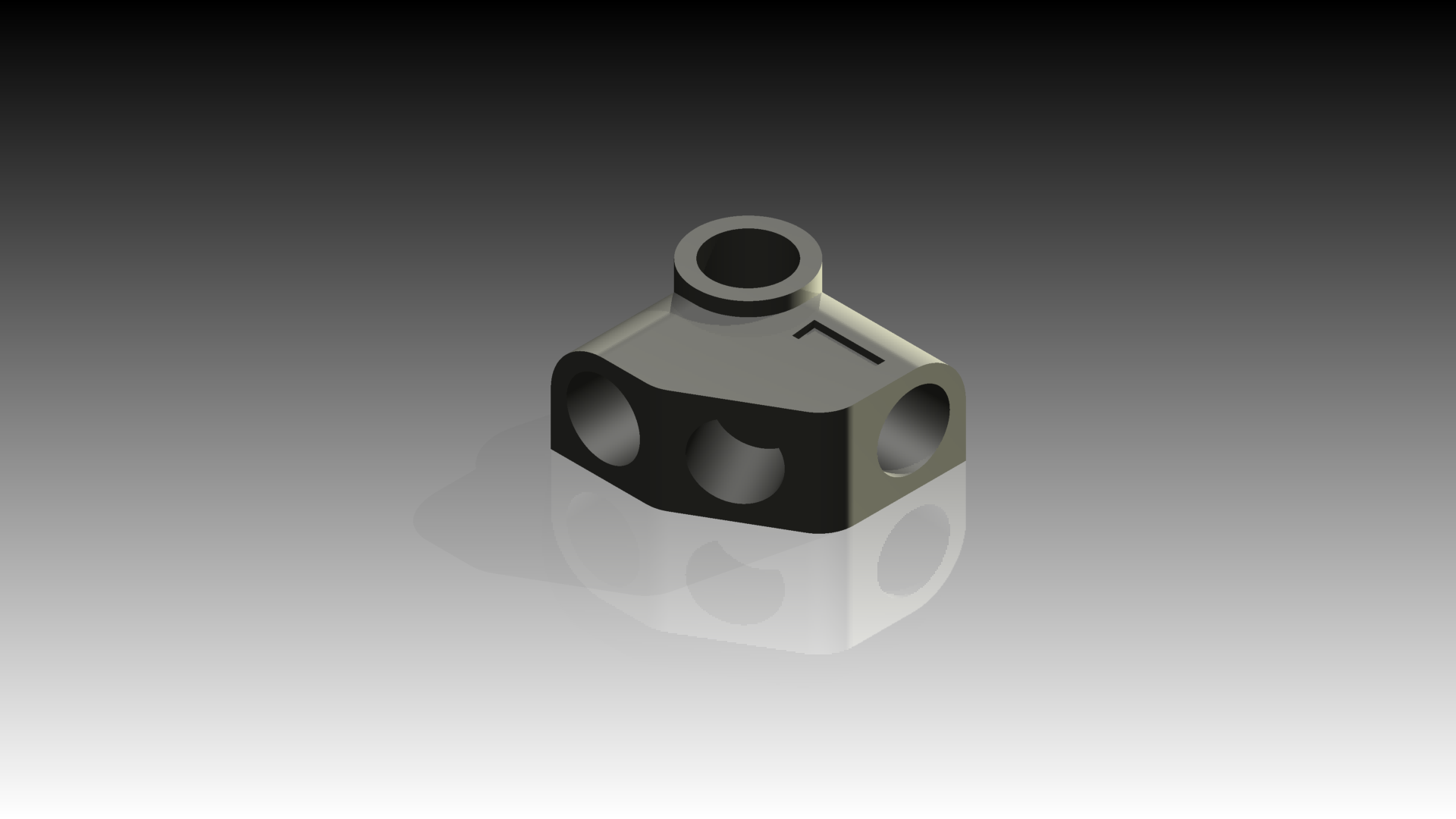 This one is labeled '1', There's also a '2', an exact mirror image.
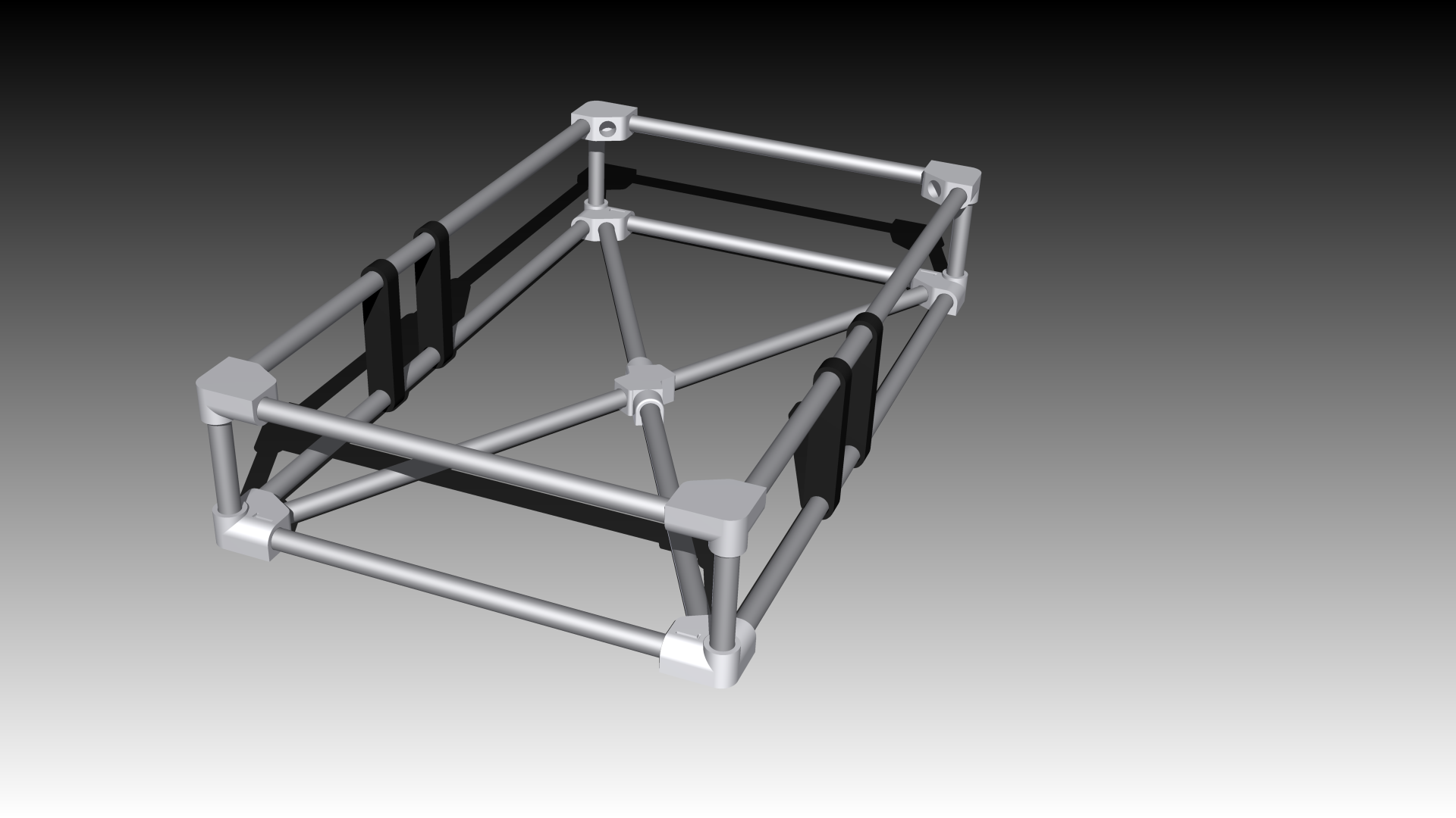 Next up: first real life assembly!
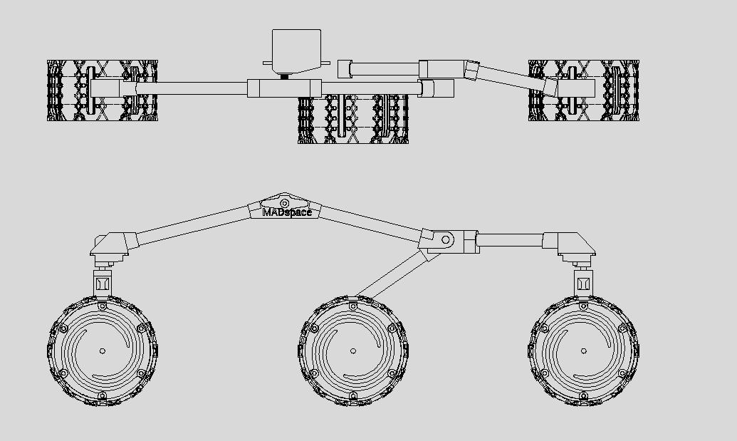
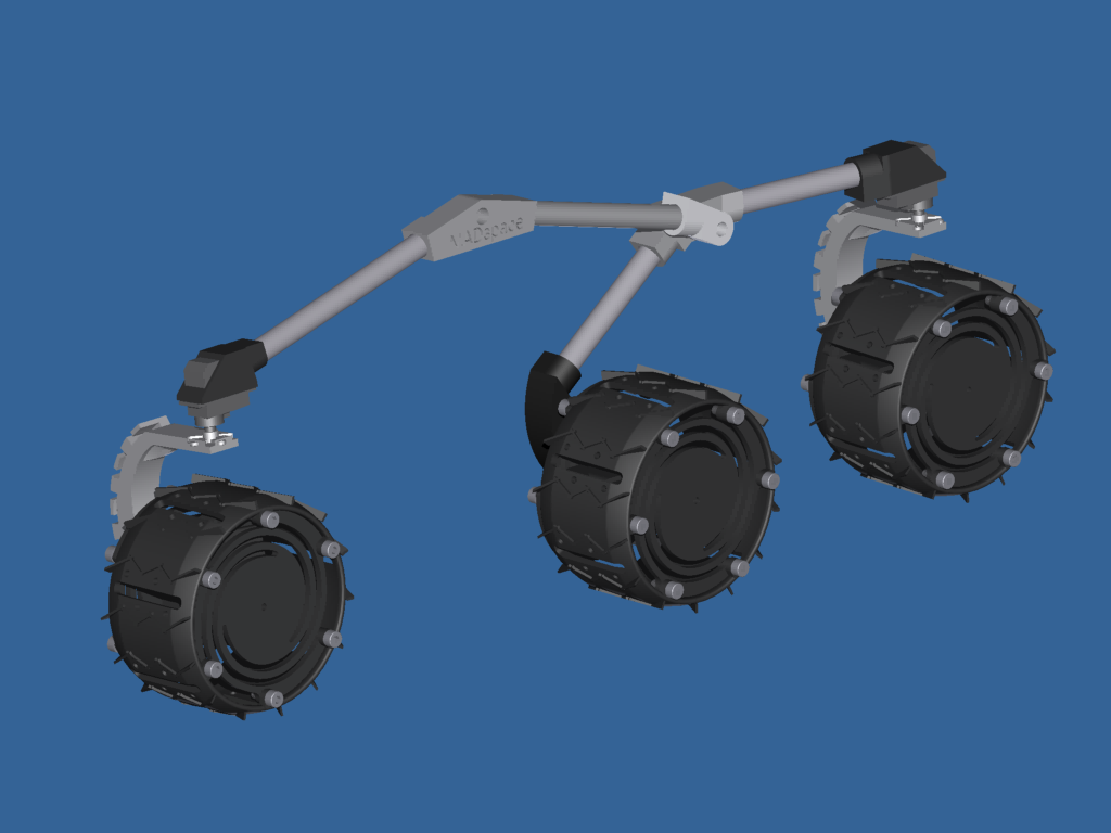 Awesome! Next up: the body.