To make the experience fit your profile, pick a username and tell us what interests you.
We found and based on your interests.
After a long time without project updates, I finally had time to assemble the new version of the LOLB. In the process of upgrading the electronics, I also ended up adding mp3/amp and a speaker to the bottom of the device.
Have fun watching the video I made after finishing in the Attraktor makerspace last night:
It seems like that cheap mp3 player/amplifier board i once bought from Pollin as well as a full range speaker that sits in the bottom of the LOLB were no bad deal at all, it even came with a remote which you can see in the video.
On the mp3 player board, I identified the pin with the unamplified analog audio signal coming from the MP3 decoder on the board and fed it into one of the Teensy 3.0's analog pins using the recommended circuit from the Teensy Audio "Docs" (the design tool). On the Teensy I'm running a bit of fft, beat detection and of course the phase dimmer timing. All the PCBs were mounted inside the LOLB's bottom with an yet to document custom milled PCB holder.
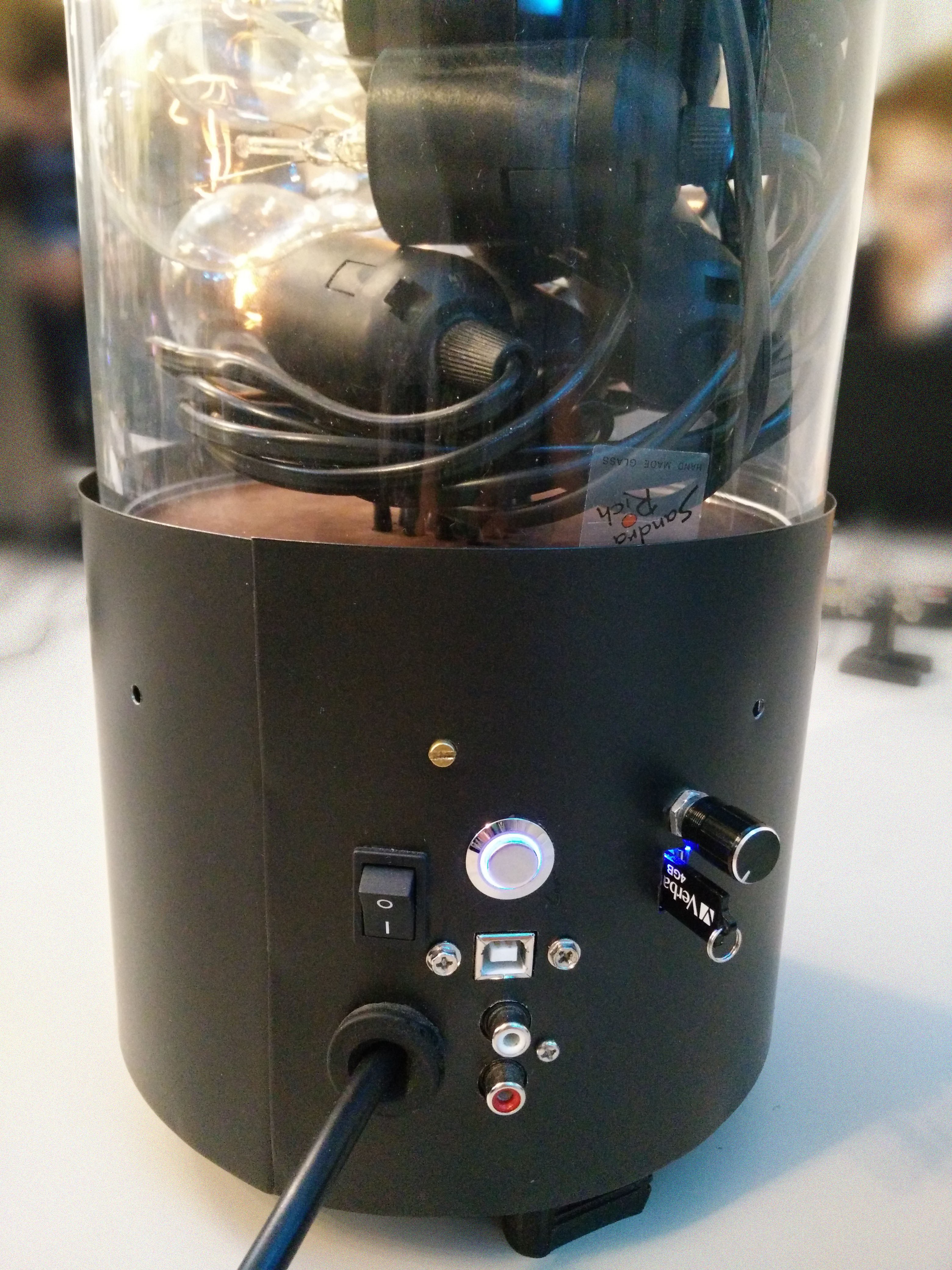
Also, a nice wooden baseplate was milled with 16 cutouts for the 16 lamp cables. I played around a lot with arranging the bulbs "nicely" in the glass cylinder, but eventually, I found it looks the best if they're just arranged in wild heap.
That steel housing originally was the base part of a glass/metal flower vase. The glass part of the vase, you might have guessed it, now sits heads over on top of the base and contains all the lightbulbs. Having the vase upcycled like that, I just needed to file some cutouts in the steel base for all the connectors and buttons/switches. It now can be comfortably reprogrammed it via USB from outside, has an illuminated pushbutton for switching through different sound reactivity modes and allows the connection of an external sound analog sound source.
Since this first LOLB is a christmas present for someone, I will give it away this month and will definitely miss it. It seems that the LOLB really is capable of radiating a nice and cosy atmosphere in a living room without being to intrusive.
So, well, I think I'll make more of them eventually, but probably not before middle of next year, since we're in the process of moving to the US and it doesn't quite make sense to build lots of 230V circuitry anymore.
The PCBs I ordered from dirtypcbs.com arrived at my door within 7 work days after I uploaded the gerbers. Besides a few drill holes and pads I layouted a little bit too small and the total absence of any connector descriptions on the silkscreen, they're absoluteley spotless and will probably do a fine job.
It's solder time. There are some SMDs on the bottom side, but, well, they're shy and have been hand soldered in a hurry, so I better took no photographs of them ;) The top side is where all the fun happens, optotriacs, triacs, fuses, 1W resistors, varistors, everything squeezed to the minimum possible space which is given by the TO-220 triacs and the fuses. I really wanted to use dirtypcbs, so I had to stick with 10x10cm maximum board outline.
If you want your PCBs to be compatible to 5mm AND 5,5mm terminals, you can just space them 5,5mm and make the holes a little larger. Then, you just group them in 2x2 blocks and they fit nicely. We don't really care about terminal distances, so we want to use what we can source the cheapest at a given time, right?
I've put together a little Teensyduino-Demo for testing the boards. They already have the cosinus and gamma correction, which is very visible I find. If I have time I'll take the extra mile and demonstrate the difference. There are only 12 bulbs attached in the demo, which were all I had, so there's a gap in the animation.
Eventually, I'm kind of happy with the boards as they are. The resistors in the zero crossing detection circuit get a bit hot, but they probably won't fail. I didn't get shocked (neither did anybody else in the Attraktor makerspace), nothing caught fire, so that's already great. And even more than that: the damn thing works :)
For syncing the dimmer channels to the AC line, I put together a simple zero crossing detection and triac control in Diptrace. It's based on this design http://playground.arduino.cc/Main/ACPhaseControl but has some additional precautions like logic level MOSFETS, varistors and fuses. Also, I had to change some components for cost and availability reasons, the specs are pretty much the same. We're using high current 16 amps continuous load triacs here, so we won't have to cool them when driving 25 W bulbs.
Disclaimer: This is 230V AC mains circuitry, so if you want to do this, know what you do and don't hold me responsible for the outcome. It's dangerous, I strongly suggest that you don't build this by just copying the circuits if you're not able to figure it out by yourself. Take this content as purely inspirational, if not satirical! THX!
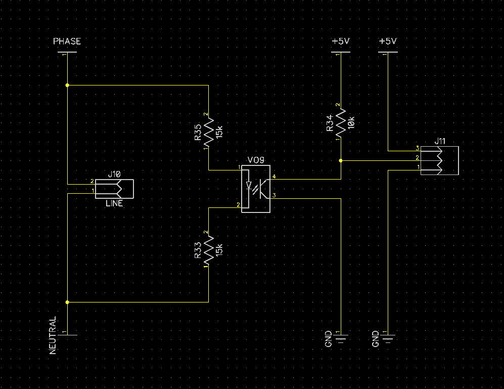
Here's the zero crossing detection circuit, I used a SFH620A AC-optocoulpler, which is pretty similar to the H11A11 from the arduino example:
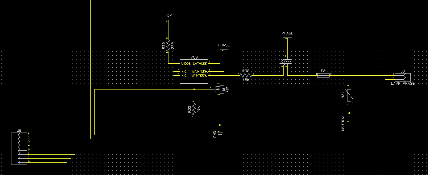
The triac driving circuit is based on powerful BT139 triacs (instead of the similar Q6015L5). Triacs are best driven by optotriacs, in this case the MOC3052-M. I will have 8 of those triac circuits and one zero crossing detection circuit on a 10x10cm pcb. Because I'm planning to drive many optotriacs, I cannot, or should not, power the optotriacs directly from any µC. The pulse, that drives the optotriacs cannot be neglectable short, so even if we're driving them at 15-25 mA, at some point, the forward current of all the optotriac emitters circuits would just sum up to something the µC cannot provide. Also, if the µC hangs, it might just blow. So I added thes nice little logic level N-MOSFETS, 2N7002, to every emitter cathode of the optotriacs. Almost any logic level N-MOSFET works here, use whatever you have. I've never had trouble driving logic level MOSFETS without gate resistor from any µC, but if you're worried you might as well add some. A pulldown however is necessary of course.
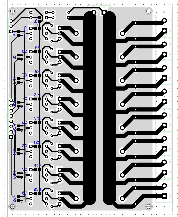
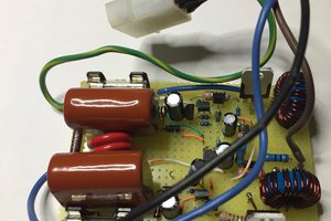
So, after some double checking on the gerber files, this went to dirtypcbs.com to get 10 nice boards. My plan is to use two of these boards for the lamp and 8 of them to make a 8x8 light bulb matrix. So, let's hope this works as planned.
In the comments esot.eric mentioned some worries about the earthed and grounded shielding copper spill covering both the logic part on the left and the mains half on the right of the PCB. He also investigated this deeper and posted some good information material that I want to integrate into this project log. He quotes his source like this:
"For each power supply stage, keep power ground and control ground
separately. Tie them together [If they are electrically connected] in
one point near DC output return of the given stage."
http://www.smps.us/layout.html
So, the mains part of the PCB should be spatially isolated from the logic part, which it is, but there's no good reason to cover the mains part of the PCB with a copper spill. First, this increases the risk of HV making it into the logic and damaging it, and second, this messes with the idea of shielding the logic part against EM irradiations of the high switching current transients. While this is definitely a design flaw that will be removed from the sources, I am not to worried about this causing too many problems in practice. The copper spill is grounded and will be earthed, so its still unlikely that failures in the mains part will...
Read more »So, it's official, we're going after phase control. The electronical basics behind building a phase control circuits is quite simple. If you want to get into it check out the detailed documentation on the arduino website: http://playground.arduino.cc/Main/ACPhaseControl
Basically, we'll kind of cut out power chunks out of each half wave of the mains power line, sorry for not putting that better, and the size of those chunks is our parameter for adjusting the brightness of the bulb. Triacs are used to do so. Triacs are a bit like transistors, just for AC, and they have the property to stay on after have been triggered until the current running through their terminals is dropping below a specific holding current, for AC that basically means they stay on until the end of the current half-wave.
So for dimming, we let the µC keep track the mains phase and register when it's crossing zero. Then we let the µC trigger the triac after a certain amount of delay time, the triac turns on and current starts to flow through the bulb until the half-wave ends. The delay between the zero crossing and triggering the triac is our parameter for adjusting the brightness of the bulb. If we set the delay to 0, current will flow through the bulb for the entire half wave, if we set it to 5000 µs (assuming 50 Hz mains frequency and 100Hz half-wave frequency), current will flow through the bulb for half of the half wave, which will basically result in the lamp beeing dimmed to 50% power output. If we wait forever and never trigger the triac, the bulb is plain off. This repeats 100 times a second, for every half-wave.
This project log however shall deal with a different problem that appears when using phase controlled dimming, which is that the timing delay between zero crossing and does not map linear to the perceived brightness of the light bulb. As a consequence, 8 bit timing control won't give you anything even close to 8 bit brightness control. Think of it like this: 1 µs of on-time at 23 V gives you about 100 times less power than 1 µs of on-time at 230 V. Since after the zero crossing, the sinoid voltage curve makes it through all the voltages within the duration of one half wave (10000µs), every µs of timing delay is weighted with a different increase of power output.
First, the voltage across the light bulb follows a sine wave, so the power output of the light bulb maps with a inverse cosinus function to the delay. I called this cosinus correction in the title.
And second, the brightness perception of the human eye is pretty much logarithmic, so an exponentially increasing light intensity will be perceived as a linear brightness increase. This can be fixed with a regular gamma correction.
And third, the light bulbs themselves will have their own power input / light output curve. I'll just asume that this is also a simple gamma curve, which makes it pretty much irrelevant. Since I'll implement a gamma curve I can simply choose a gamma that compensates for the logarithmic perception and the input/output curve of the light bulb.
So if we were to implement a function that turns our desired power output into a timing delay, it'd be as simple as that:
// power represents power values between 0 and 255, power to delay represents timing delays between 0 and 10000 µs, INTERVAL is the duration of one half wave in µs, PI is π
uint16_t power_to_delay(uint8_t power){
    return round(float(INTERVAL)*(acos(-1f+2f*float(power)/255f)/PI));
}
The next thing we have to take care about is the gamma curve:// power and power_to_brightness represent the light intensity with values betwee 0 and 1, GAMMA is the desired gamma value between 0.0 and 1.0
uint8_t power_to_brightness(uint8_t power){
return round(pow(float(power)/255f,GAMMA)*255f);
}However, by combining the above functions, we get twice the rounding errors, better is having one function for both tasks:uint8_t brightness_to_delay(uint8_t power){
return round(float(INTERVAL)*...
Read more »
Dimming or switching lightbulbs can be done in many ways. MOSFETs, Triacs, SSRs, relays, all of them somehow do the same job. However, MOSFETS need DC or at least half-bridge-rectified DC, therefore you can PWM them easily. Alternatively, you can skip the rectifier and use triacs. However, you cannot just PWM triacs and a zero-crossing detection and precise timing control then becomes necessary. If you just aim to switch the bulbs on and of, mechanical relays or SSRs could be an option, too. In fact, the old version used mechanical relays, which is probably the worst choice of all listed options here, but I was young, dumb and without money, all I had was a bazzilion of miniature relays.
Before rebuilding the electronics, I’ll try to make a sophisticated guess on which way is the best for this application. I literally went back and forth between the possible options, which shall be documented here.
Low voltage or mains voltage
Low voltage yields less direct danger, but still can cause fires. In your home, the mains line will be secured by at least one leakage current fuse, so any mistake you make will darken out your home in an instant instead of slowly catching fire. MOSFETs are way cheaper for lower voltages than higher voltages. Triacs work for both. Low voltage lighting requires transformers or switching power supplies, adding up to the cost of the project, if you're using LEDs that might not be a big problem.
AC or DC
DC allows simple PWM using MOSFETs but MOSFETs will produce more heat with higher switching frequencies, AC allows phase control with less switching losses but requires a zero detection circuit and precise timing control.
Triac, SSR, mechanical relay or MOSFET
Triacs can be dimmed with phase control, DA-SSRs usually bring their own zero-crossing detection, so no dimming possible, DD-SSRs are slow and very expensive. Triacs are generally much cheaper than SSRs, but require additional optotriacs to drive them. When driving many optotriacs or SSRs from a micro controller, additional logic level MOSFETs become necessary. Mechanical relays may be too loud for this application and will wear out quickly.
LEDs, low-voltage halogen or 230V light bulb
LEDs are very efficient, versatile and easy to control. In fact, doing this with LEDs is so simple, for a product one should really do this with LEDs and try to get the light bulb aesthetics with some tricks on the way. However, a project must be challenging, too, and luckily I cannot imagine how to get this aesthetics with LEDs. Reworking lightbulbs by removing the filament and adding LEDs could be an option, but seems rather tedious than challenging. 12 V halogen could be an option and could be driven by cheap low voltage MOSFETS. 230V light bulbs are very cheap and have the best aesthetics, however they would require triacs with phase control since 230V MOSFETs are rather expensive. I’ve seen 12 V E27 light bulbs, but they were also expensive and would require a transformer or power supply.
Cost considerations
The 16 lightbulbs in the jar are supposed to be controlled individually, so we end up having 16 analog channels. Going after the best possible aesthetics, good old 230V lightbulbs, maybe even vintage style edison bulbs, are the choice. Using a half-bridge-rectifier and 16 high voltage MOSFETs, just PWM’ing them, is possible, but they are very expensive. Using 16 triacs is much cheaper, since the zero crossing detection circuit only has to be built once for all 16 channels. Additional logic level MOSFETs will be necessary either way. These cost considerations depend on which parts you can source for which price.
Choice
I chose to use 230V E27 light bulbs and triacs. After going into the actual component prices I realized that even the necessity of having additional optotriacs for driving the power triacs is still cheaper than any high voltage MOSFET and any SSR I could find anywhere. Also, this is a nice project for digging into phase controlled dimming.
Create an account to leave a comment. Already have an account? Log In.
Become a member to follow this project and never miss any updates
 Tony
Tony
 Rue Mohr
 Yann Guidon / YGDES