-
IT'S ALIVE!
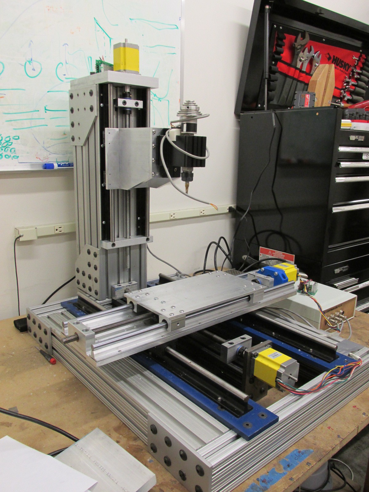
11/10/2015 at 16:03 • 0 commentsHere is a video description of the hardware, electronics and the software of my machine. Still a ways to go but it is moving. Hopefully I can make some chips with it soon.
-
Continued Progress
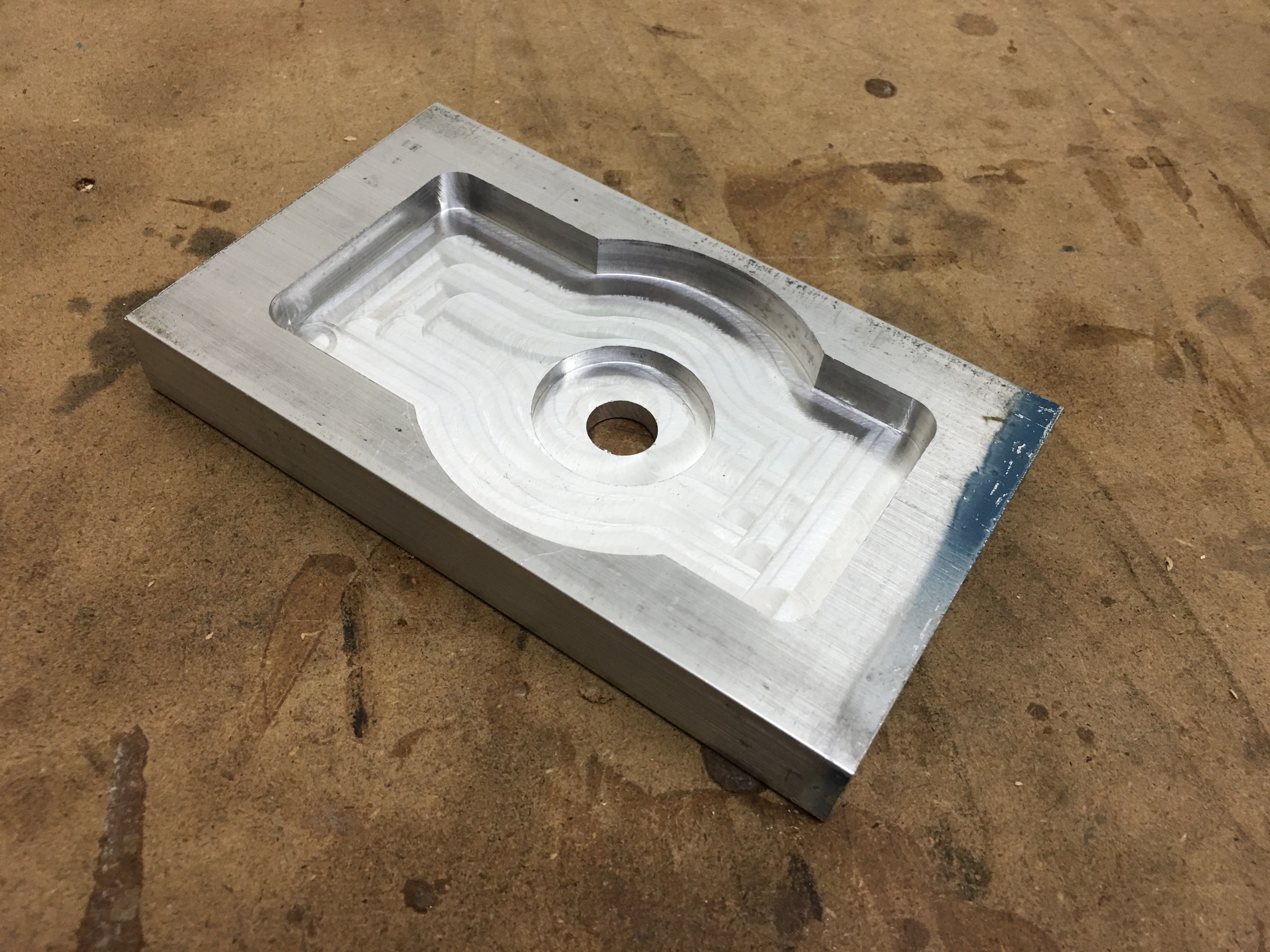
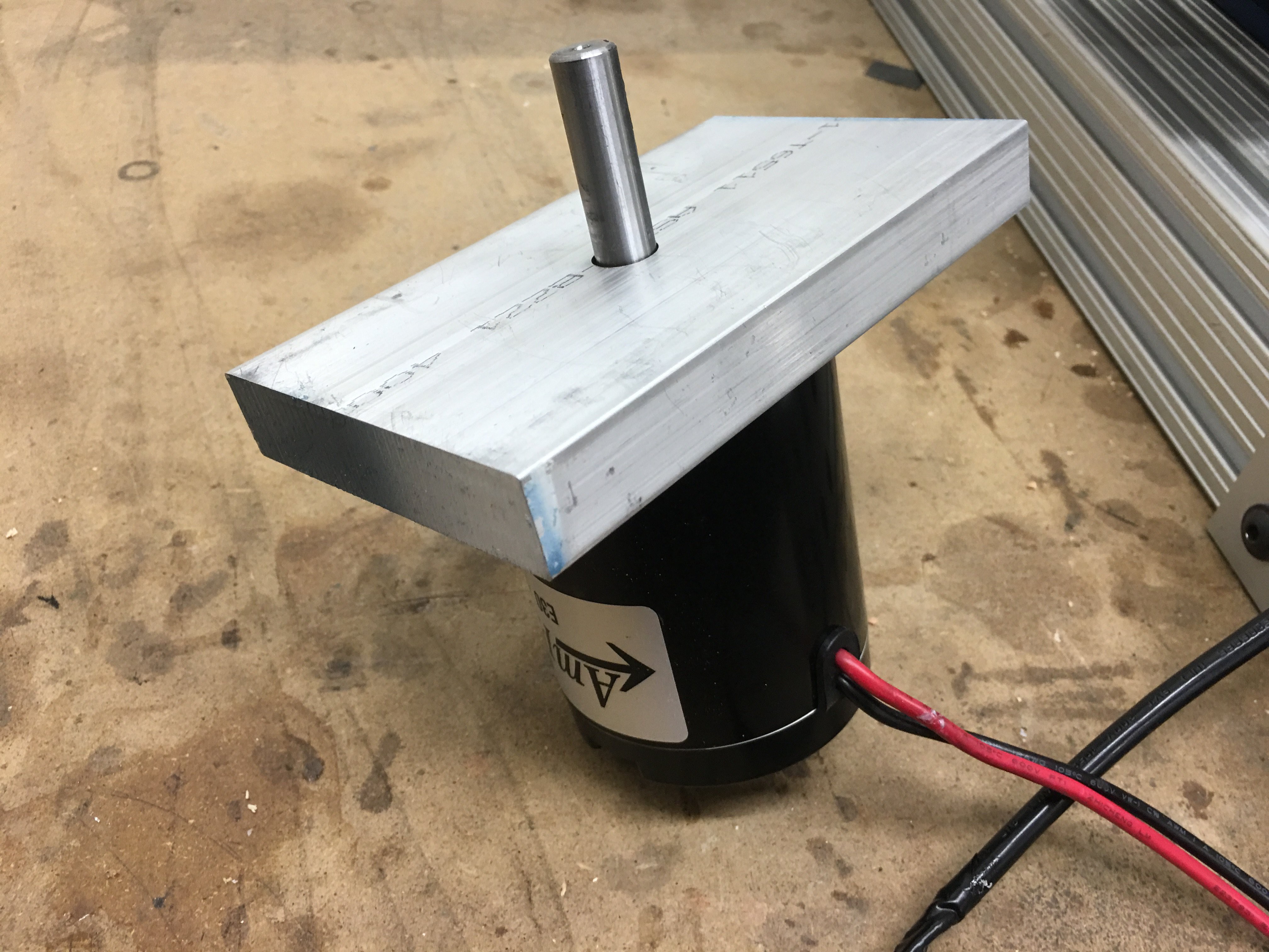
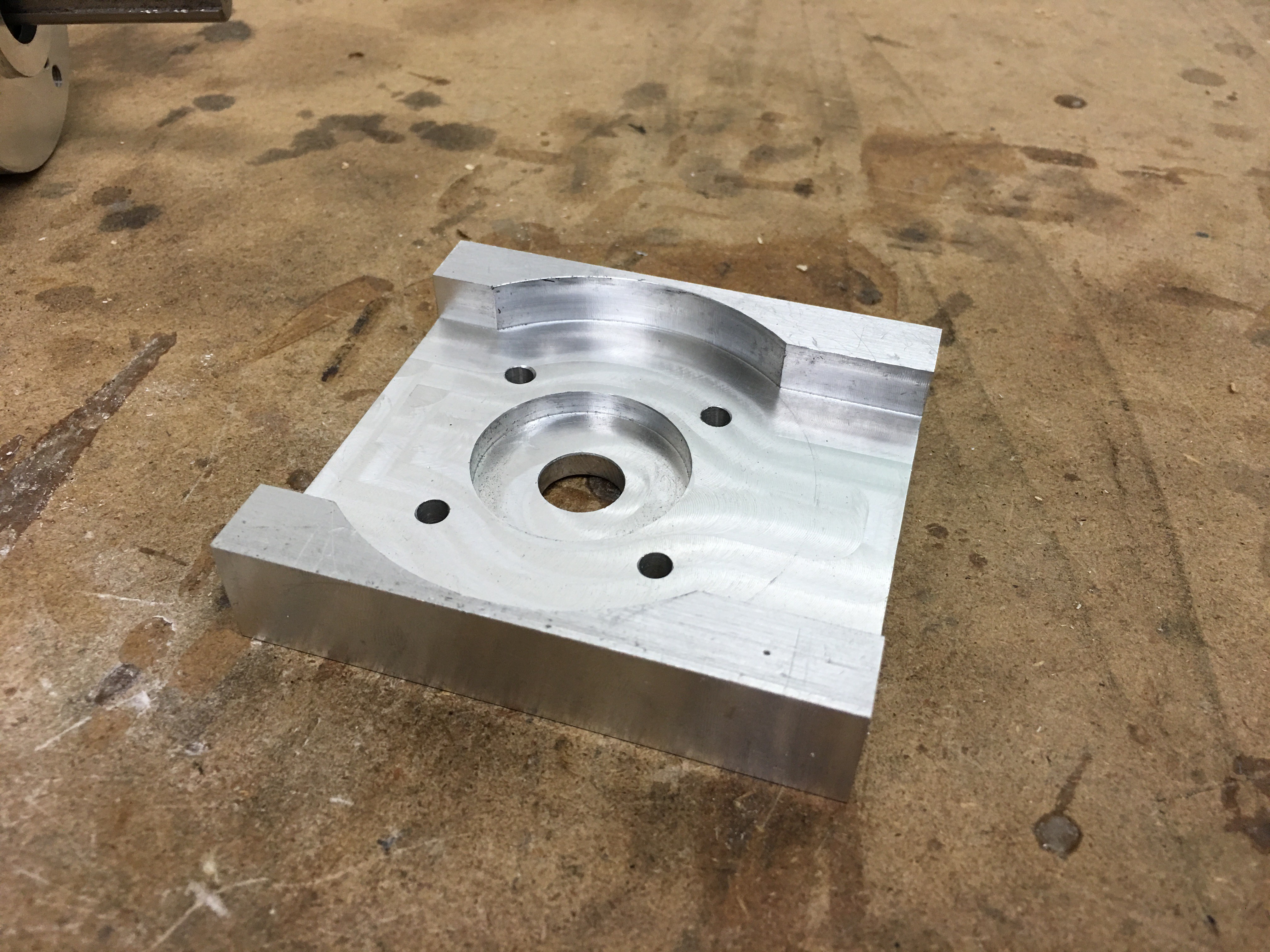
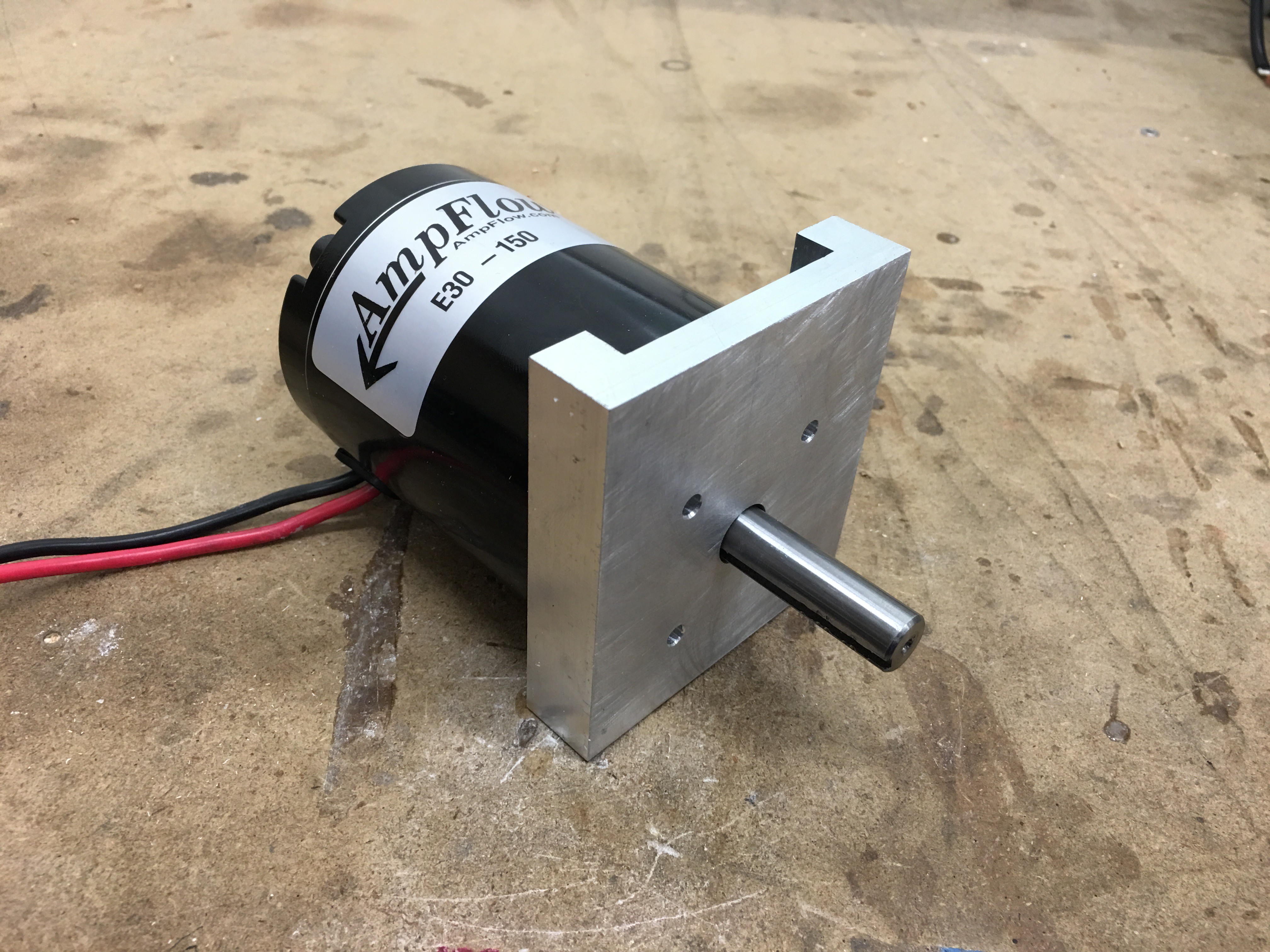
11/02/2015 at 19:48 • 0 commentsI have been working on so many projects that the CNC mill has slowed a little. I needed to go across town to machine a part and I kept putting it off. But I finally was over there and did the machining for the new motor mount. As always pictures are more interesting.
And the motor fits great. Now just gotta machine a few bolt holes and mount it together.
With the cnc milling part completed it was fairly straightforward to put it in a manual 3 axis mill and finish up the main shape. I used the center hole as a reference and drilled the motor mounting holes, and cut the ends shorter.
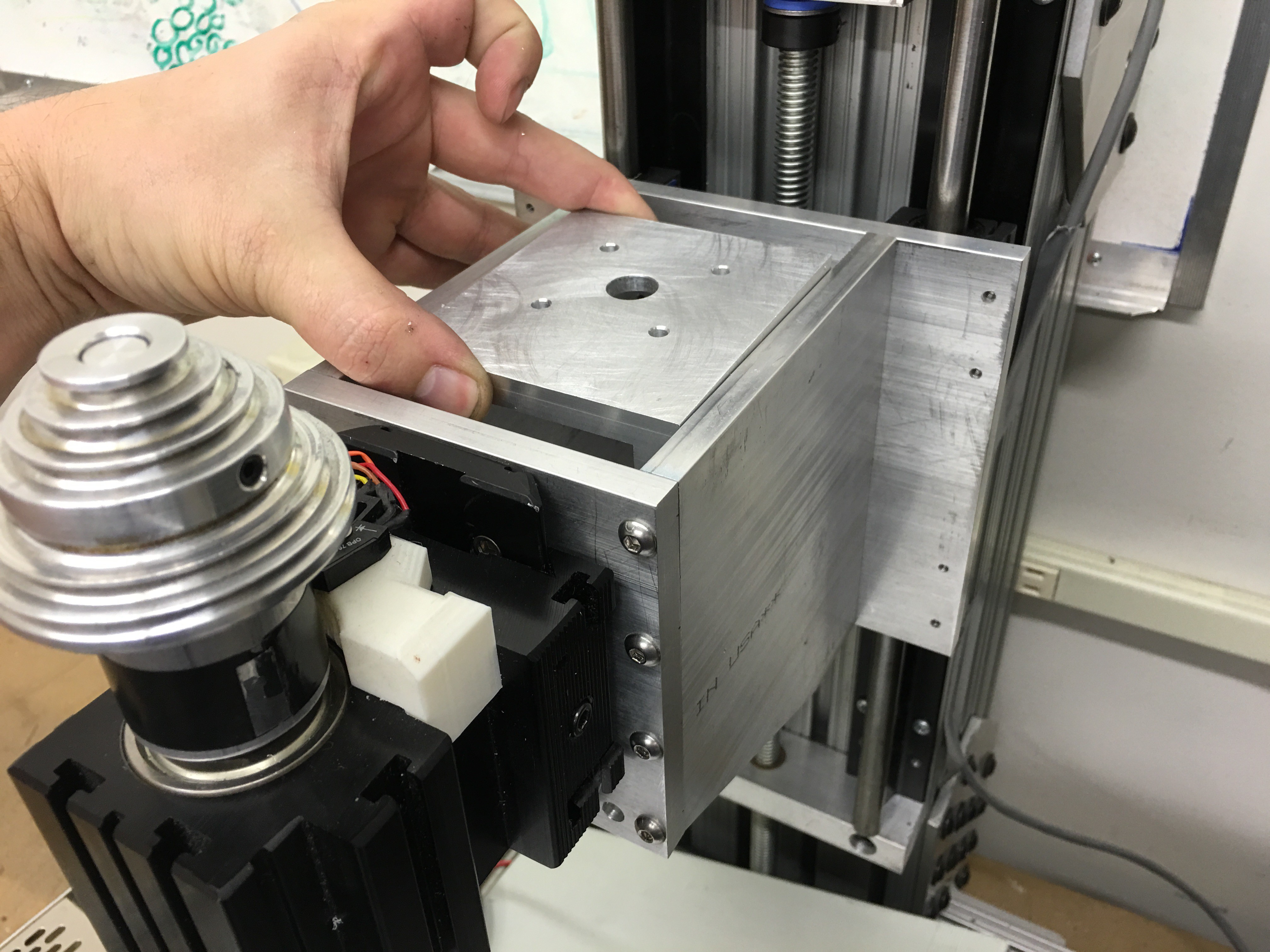
I also machined the width so that it would fit into my spindle mount and slide back and forth easily.
-
Small Update
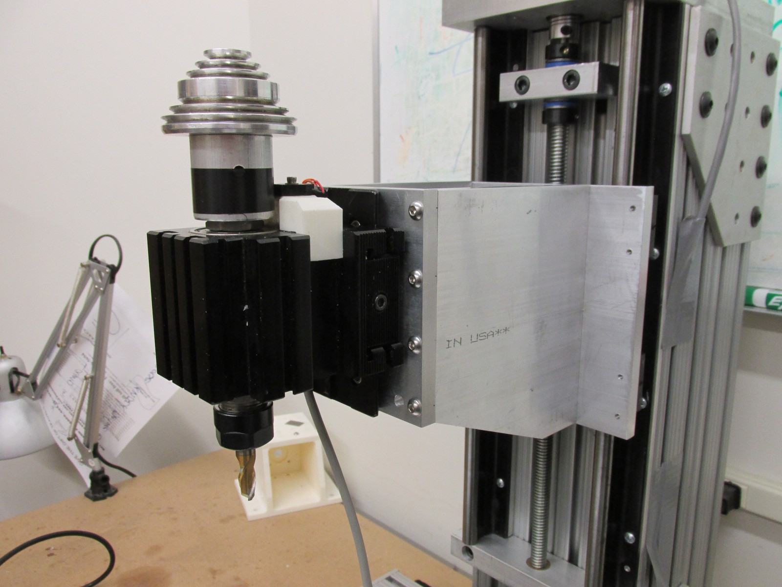
09/18/2015 at 22:18 • 0 commentsI got the screws I needed to assemble the spindle mount. So today I spent a little time getting the mount fully assembled and mounted on the mill. It fits very well and runs smooth. I am really happy with how the spindle mount turned out. I started building cnc machines about 7 years ago. The first one was made from wood and scrap. I made all the parts by hand on woodworking tools. This project has motivated me to learn to machine better parts. I learned how to use a manual mill, lathe, weld, powder coat, anodize and all sorts of other things.
It is a really nice feeling when you bolt everything together and it fits great. I can't wait to get the motor mount machined and have this making chips.
-
New Spindle Mount
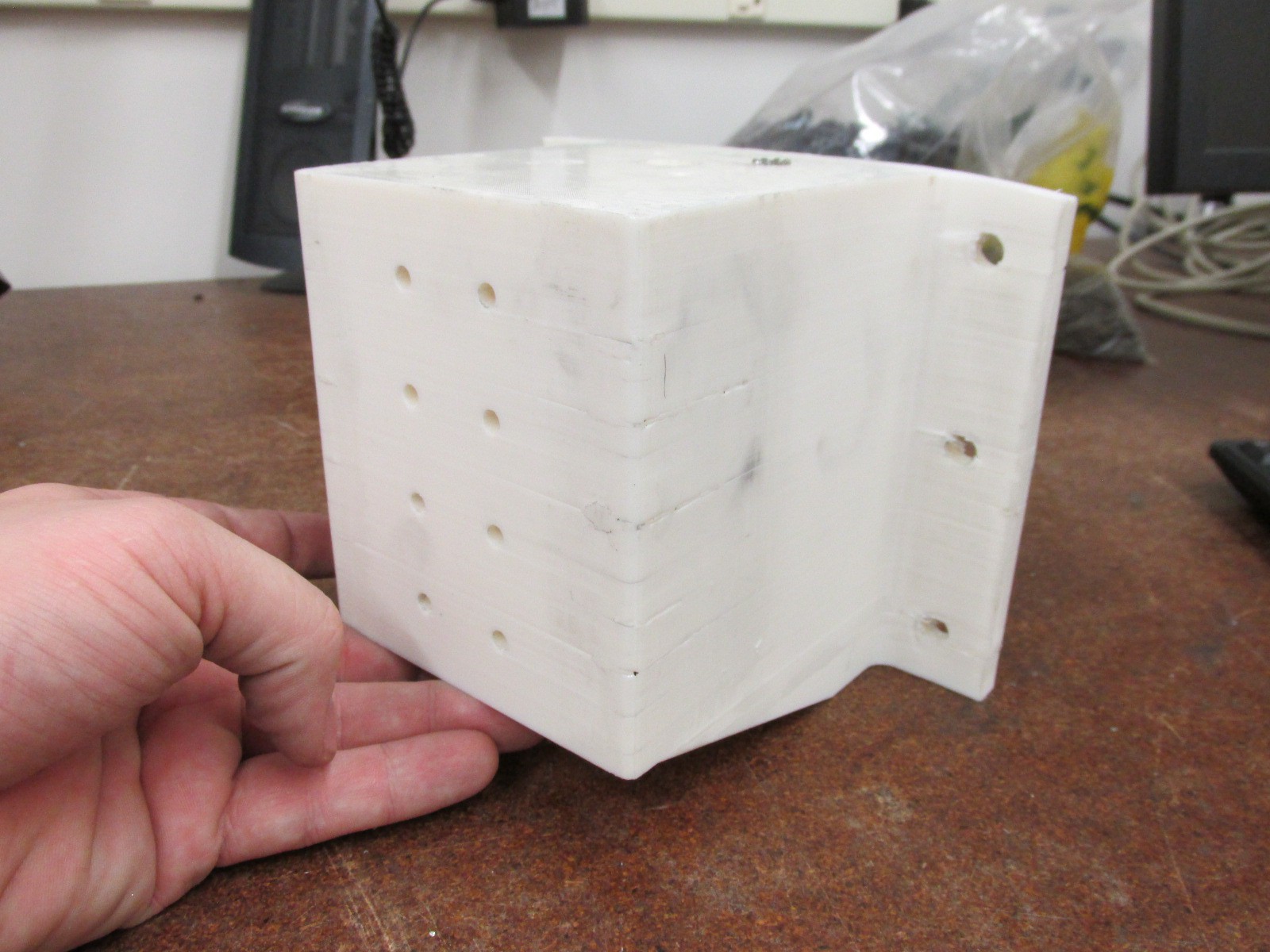
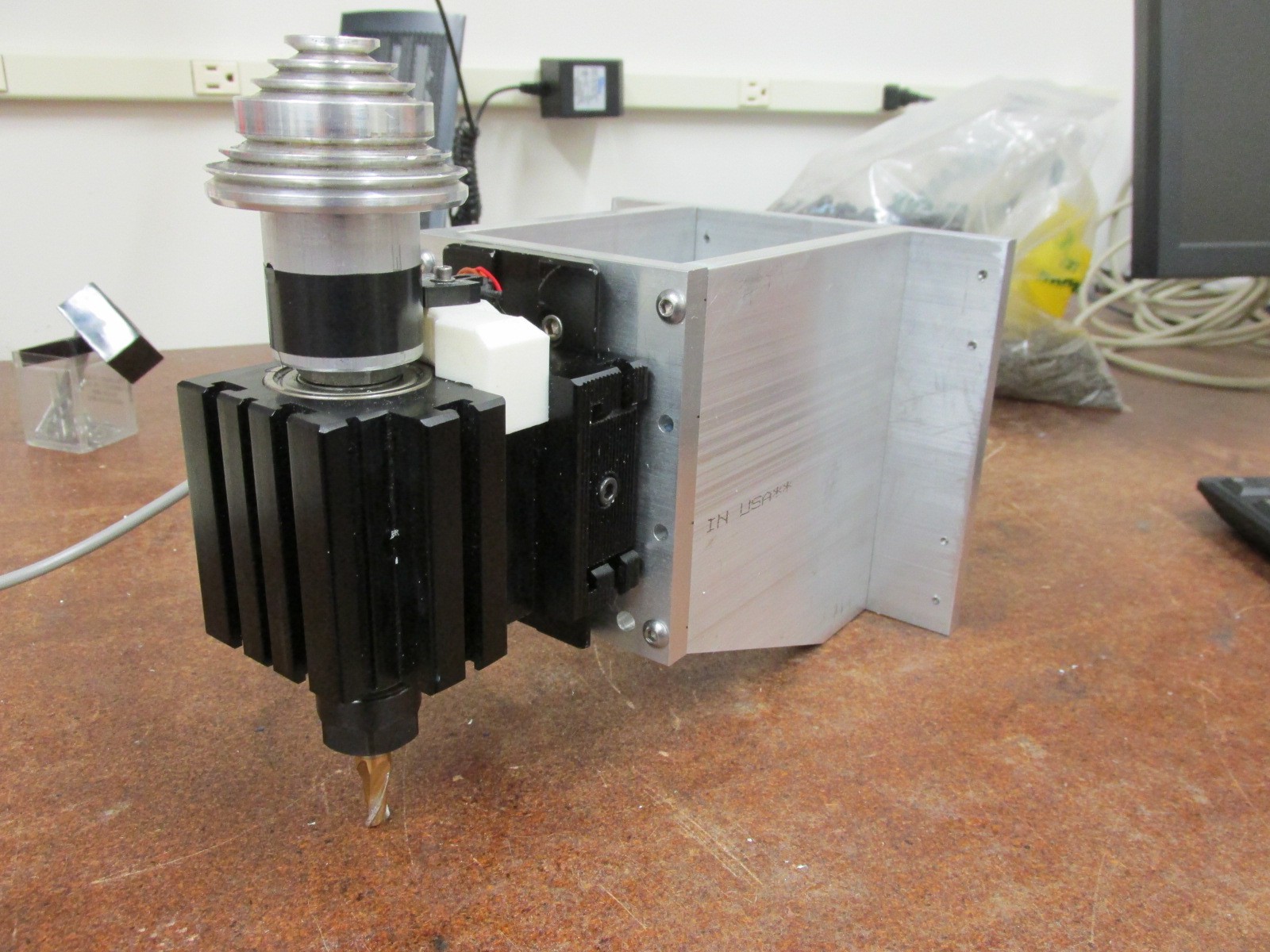
09/17/2015 at 21:26 • 2 commentsI finally got around to machining a new spindle mount. I 3d printed one a while back to help figure out how everything would fit together. I knew I wanted an aluminum one, but I used the 3d printed version to get the spindle mounted, figure out the connection to the motor, hooking up the tachometer and working on the Z axis.
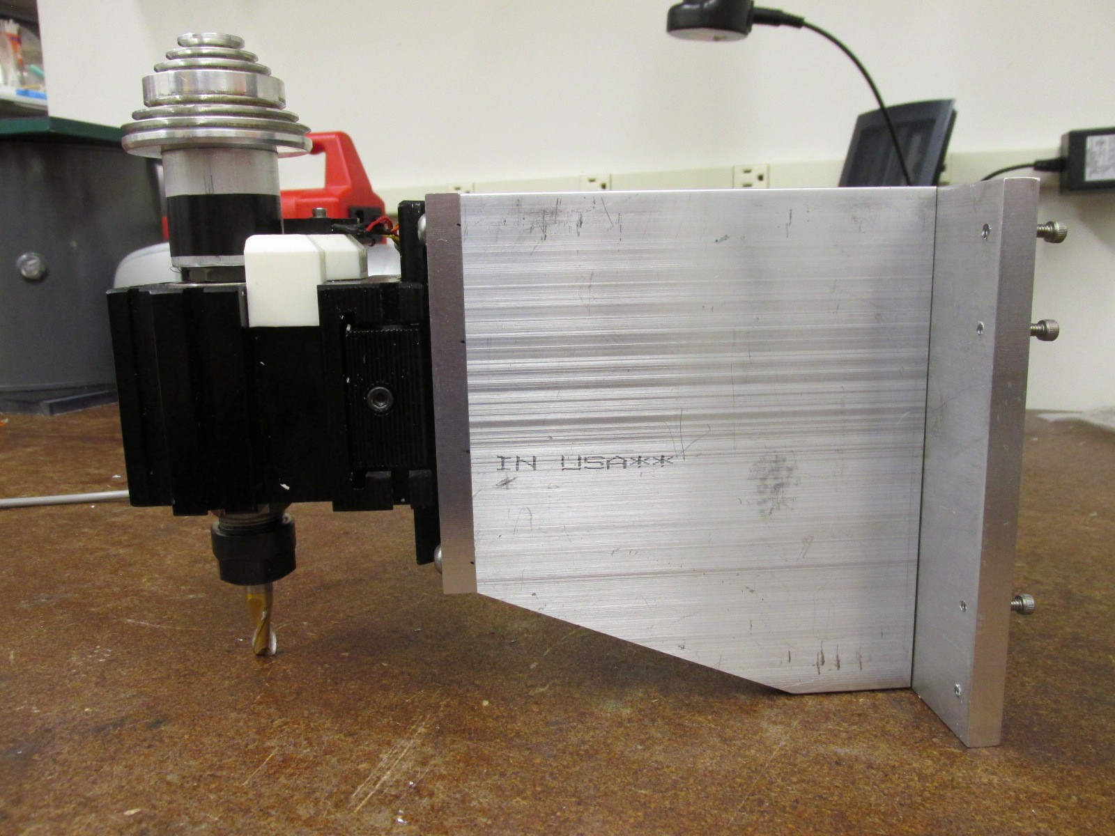
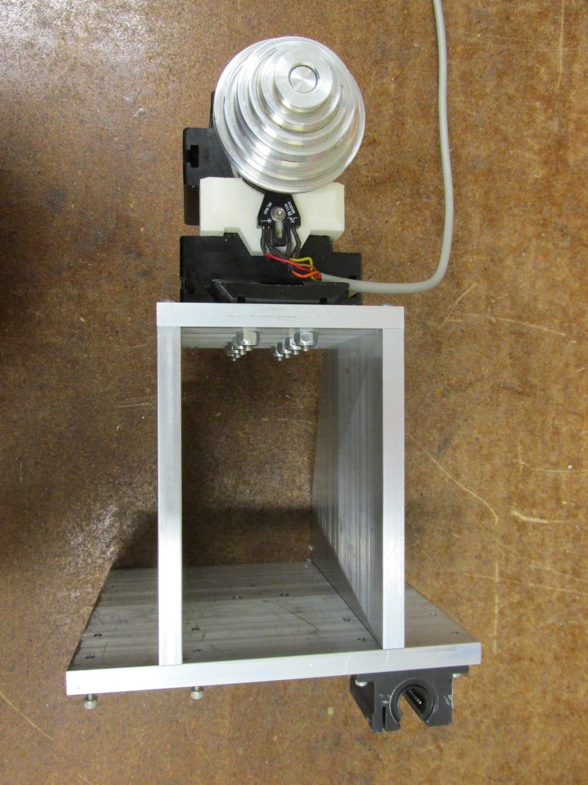
Now that most of that is worked out it was time to make an aluminum one. I started with some 3/8" thick aluminum. Then cut it down to rough shape on the horizontal bandsaw. Next I finished the size and drilled all the holes. Most of the work was done on a manual mill using the normal vice. But to drill the holes in the end I clamped it to a right angle plate. Nothing too complex about the design. I will probably put some thread locker on the screws at some point. But I want to get it together and working before I do that.
Plastic Version
New Aluminum Version
Side View
Top View. I only have one bearing screwed on to test the fit. I am waiting for some screws to come in the mail.
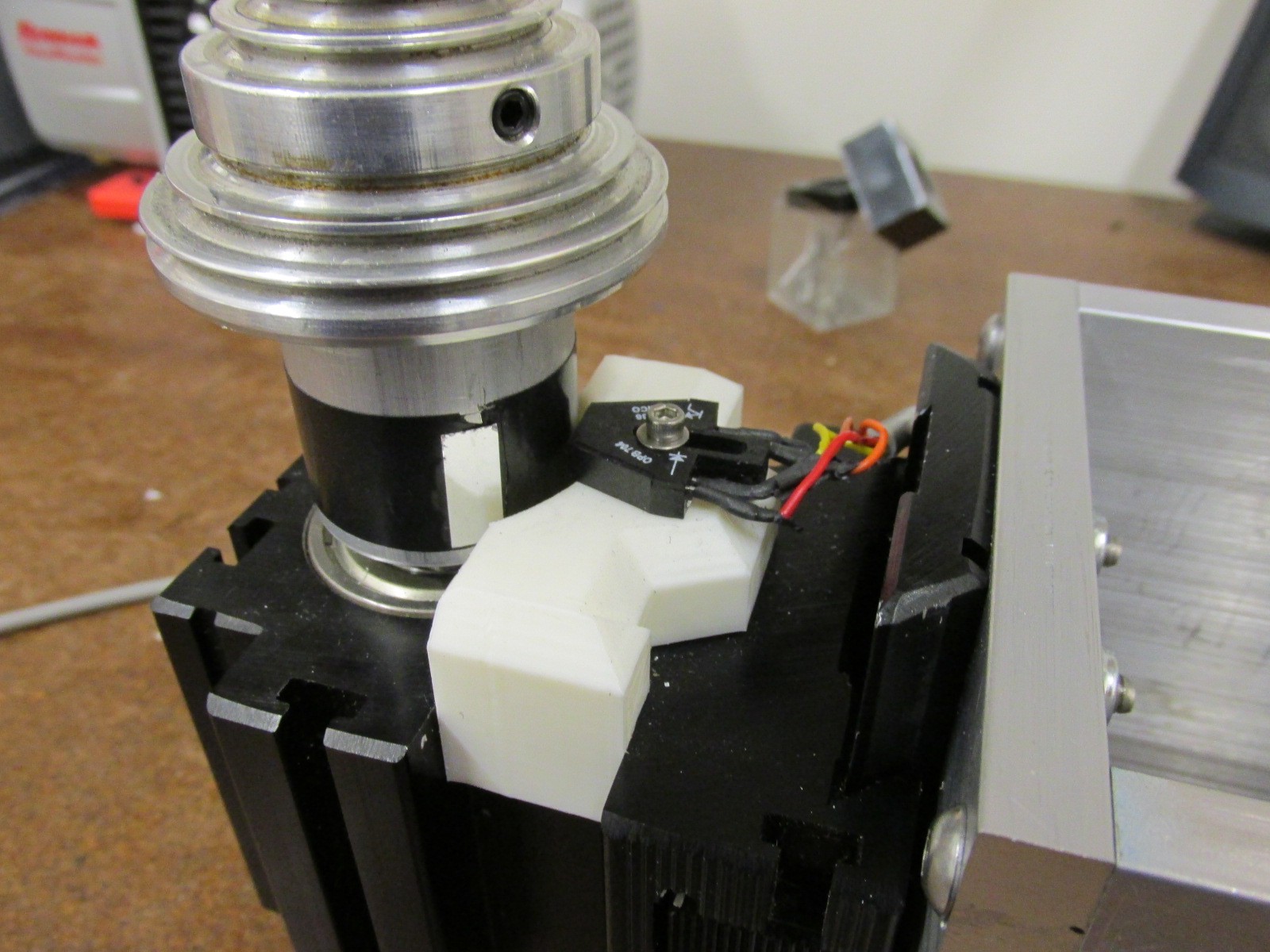
Here you can see the spindle encoder. I 3d printed a small bracket to hold the sensor in place. There is a small reflective sticker on the spindle shaft. This will give me an accurate feedback of the spindle RPM.
-
CNC Controller
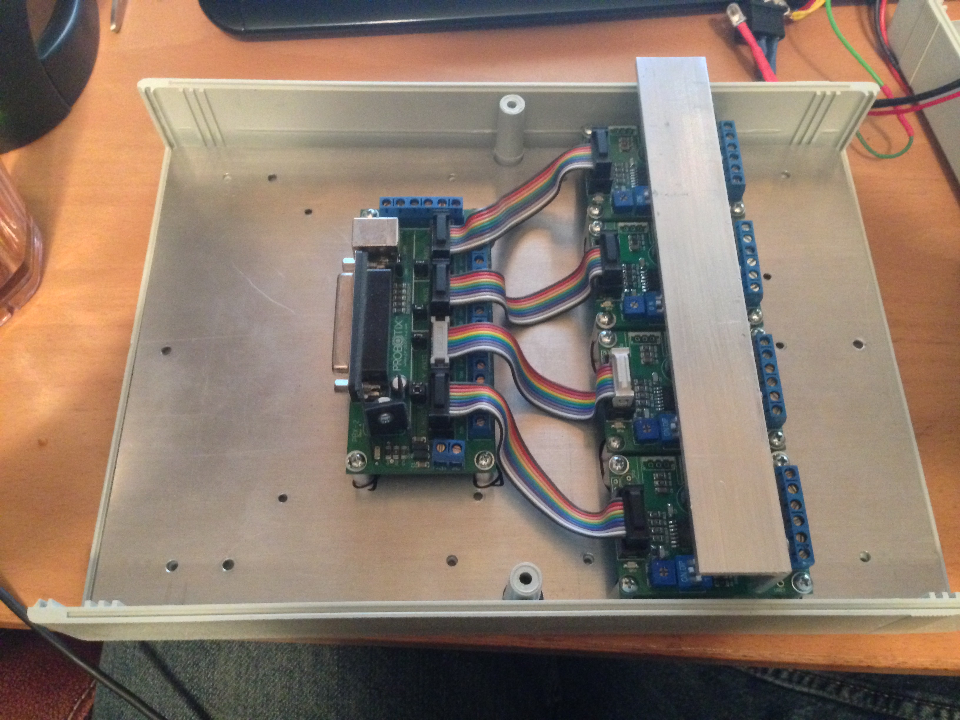
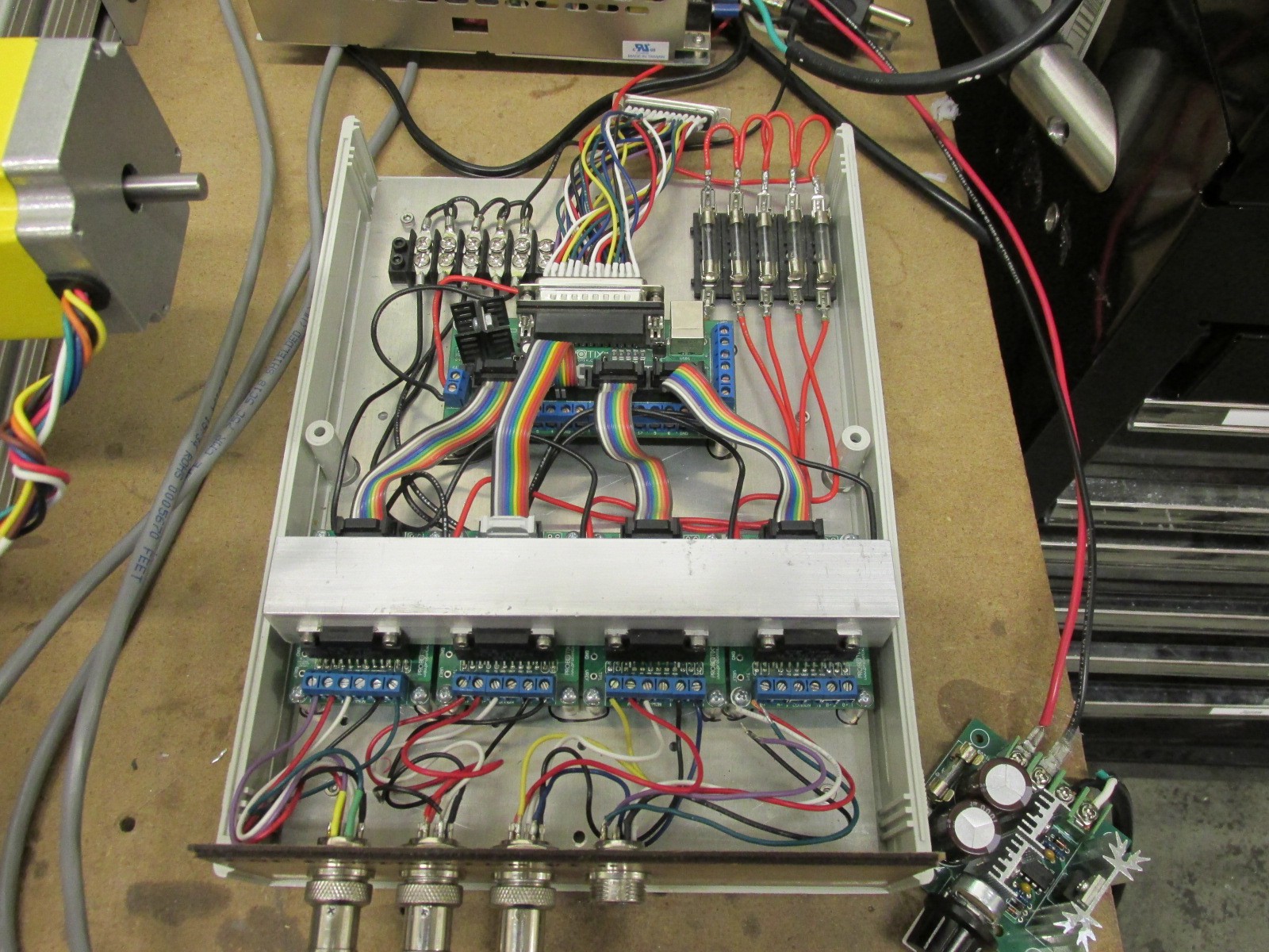
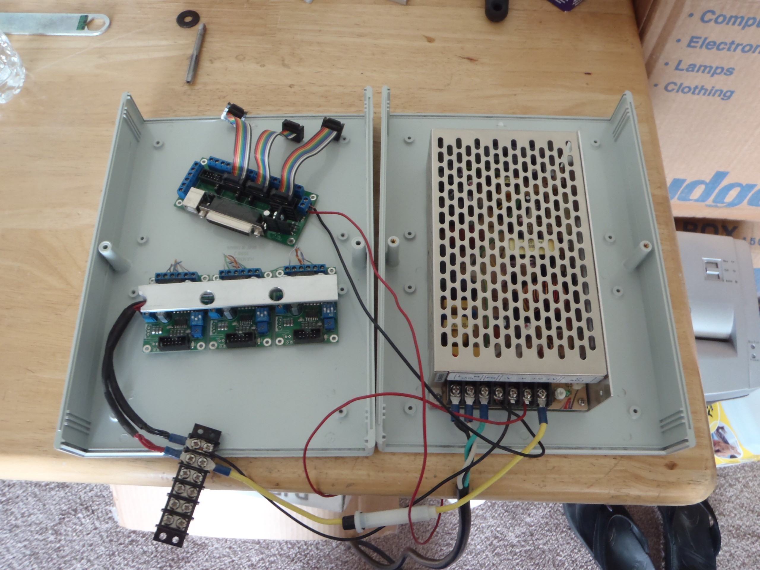
09/15/2015 at 04:24 • 0 commentsI did some work for a guy and in exchange he paid for the work by buying me a CNC kit from Probotix. The don't sell these stepper motor drivers any longer. But they work pretty well. I got the 4 axis kit because I was planning on using two stepper motors for the z axis. Now that the design has changed I will be able to have a 4th axis if I want. I wired it up and started to mount it into a project enclouser.
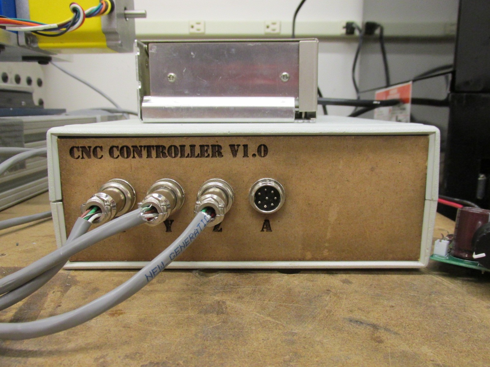
I laser cut a front face plate for it and mounted some XLR connectors for the motors. This makes it easy to wire it up once and forget it. The plugs are keyed so you can only put them in one way.
I added a terminal block in for the motor power and put a fuse on each of the motor controller and DB25 breakout board. The motors have a 3 amp fuse and the breakout has a much smaller one. It is important to put a fuse on each motor driver because they can draw up to 3 amps each. So with all the axis running I could easily be pulling around 12 amps. But you dont want 12 amps to go into any one board. All the motor controllers are heatsinked together with a peice of angle aluminum and some thermal paste.
-
Lessons Learned
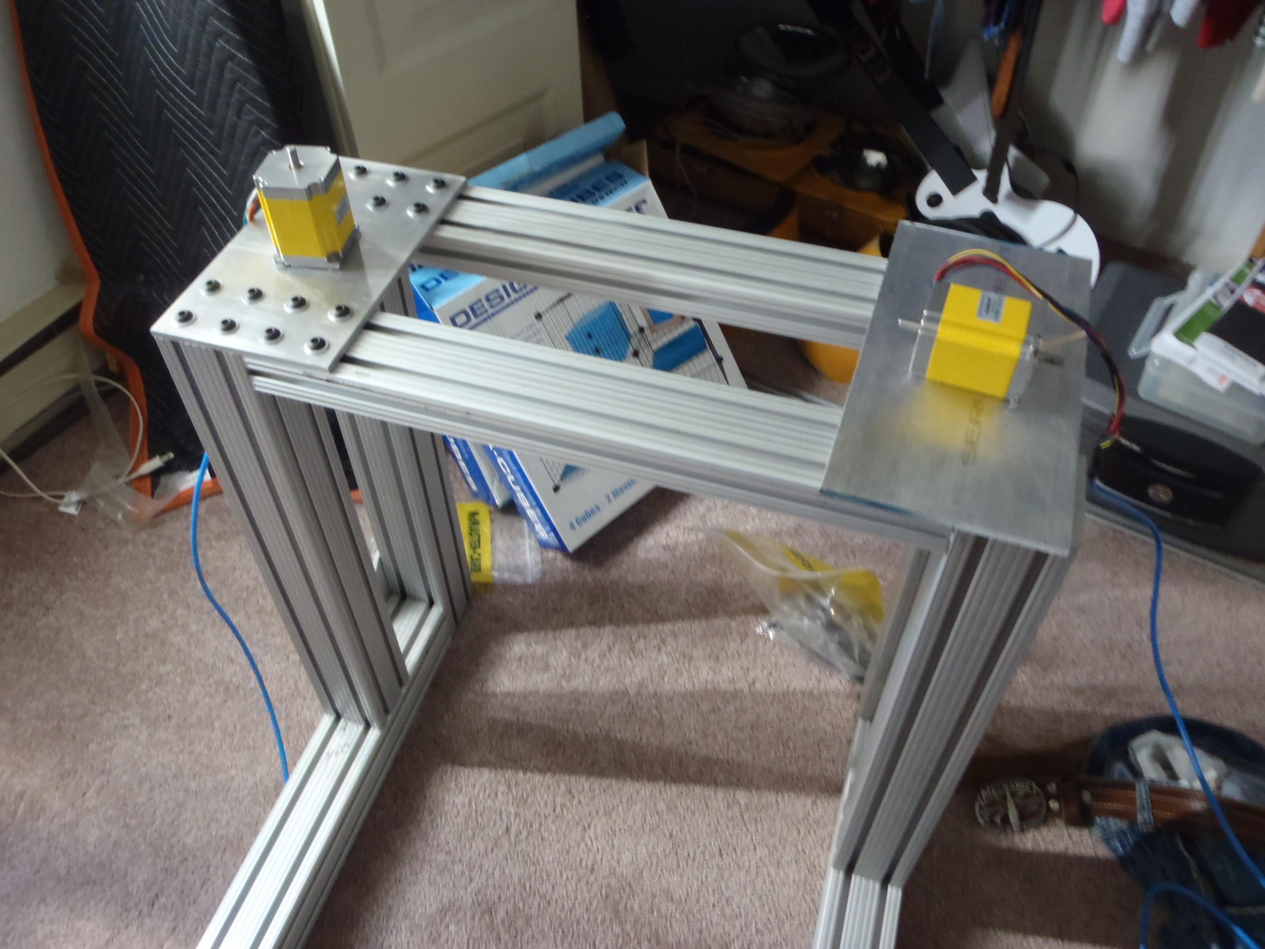
09/15/2015 at 04:14 • 0 commentsWell I really thought that I had a great design. It probably took me about 6 months to get the dang thing together enough to realize that the Z axis was just never gonna work that way. The stepper motors stalled and couldn't lift the Z axis at all. I had them directly coupled to the acme screws and that didn't work. Then I tried moving the motors to the side and connecting it with a set of pulleys and timing belt. This let me double my torque and it still stalled. It was a major set back. I really was upset. But sometimes you have to have a set back to move forward.
I set the project aside for a while and after a break I came back and redesigned it. It is a little funny but the more I worked on this project, the more it looks like a traditional cnc mill. I guess I was reinventing the wheel and as I learned what wouldn't work it steered me more and more to the traditional designs. I guess other people figured it out before me. Maybe I was a little slow.
-
Another Try
09/15/2015 at 03:57 • 0 commentsBased on what I learned with my first cnc I knew that I wanted something better. It had to be more rigid and more accurate. The size was not as big of deal as I once thought. My first cnc was 24"x24"x4", The x and y bed was bigger than I needed, but the Z was too small. It could only cut wood and plastic. I tried aluminum once and it was horrible. I also was not happy with using a palm router for the spindle. I didn't have control over the speed and it could only hold 1/4" bits.
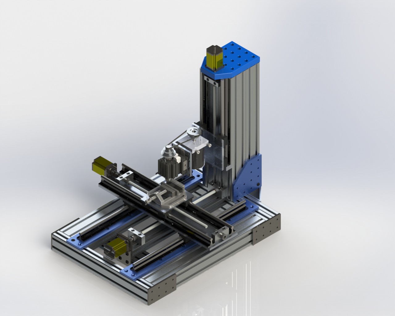
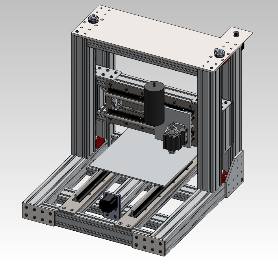
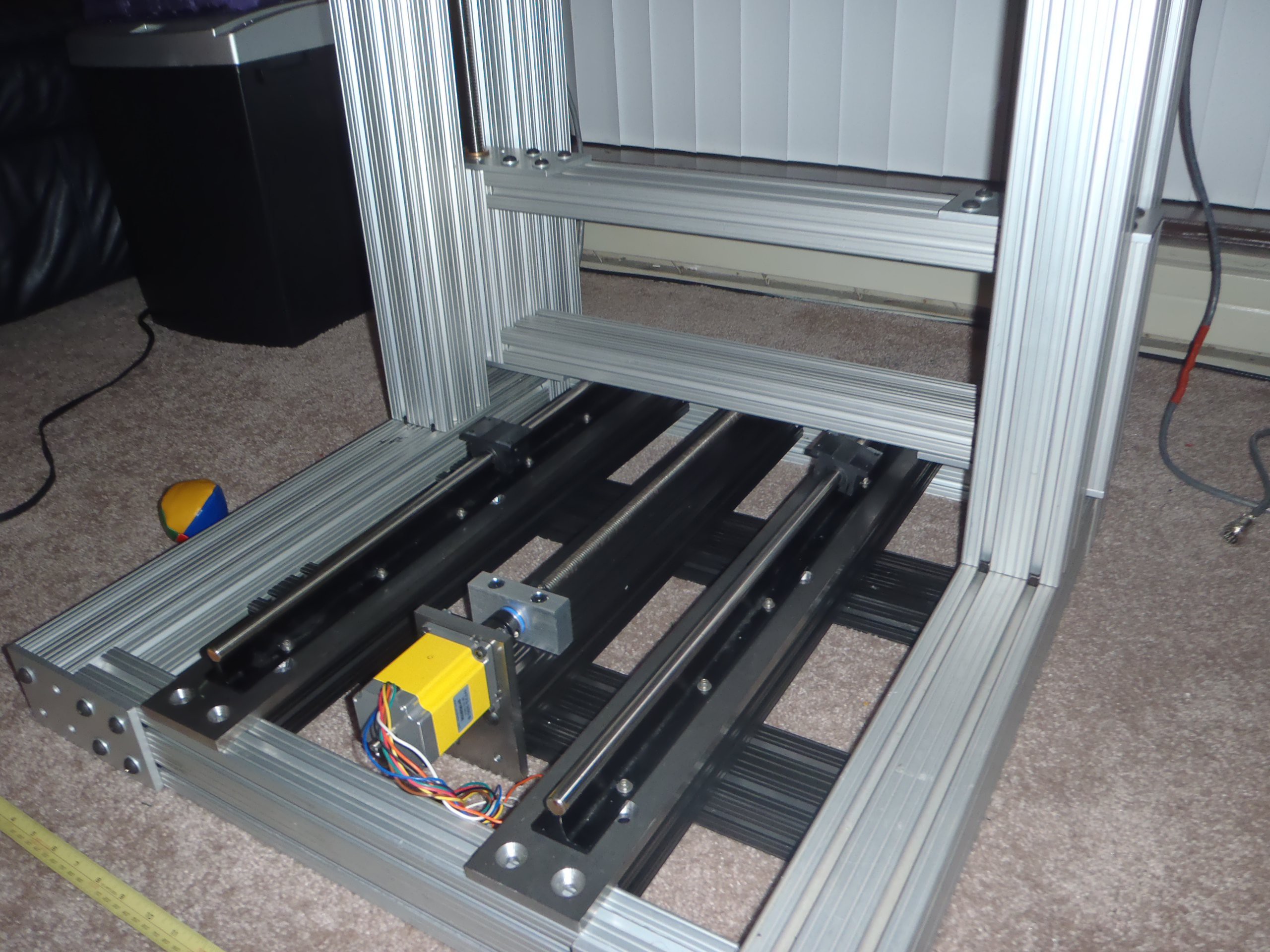
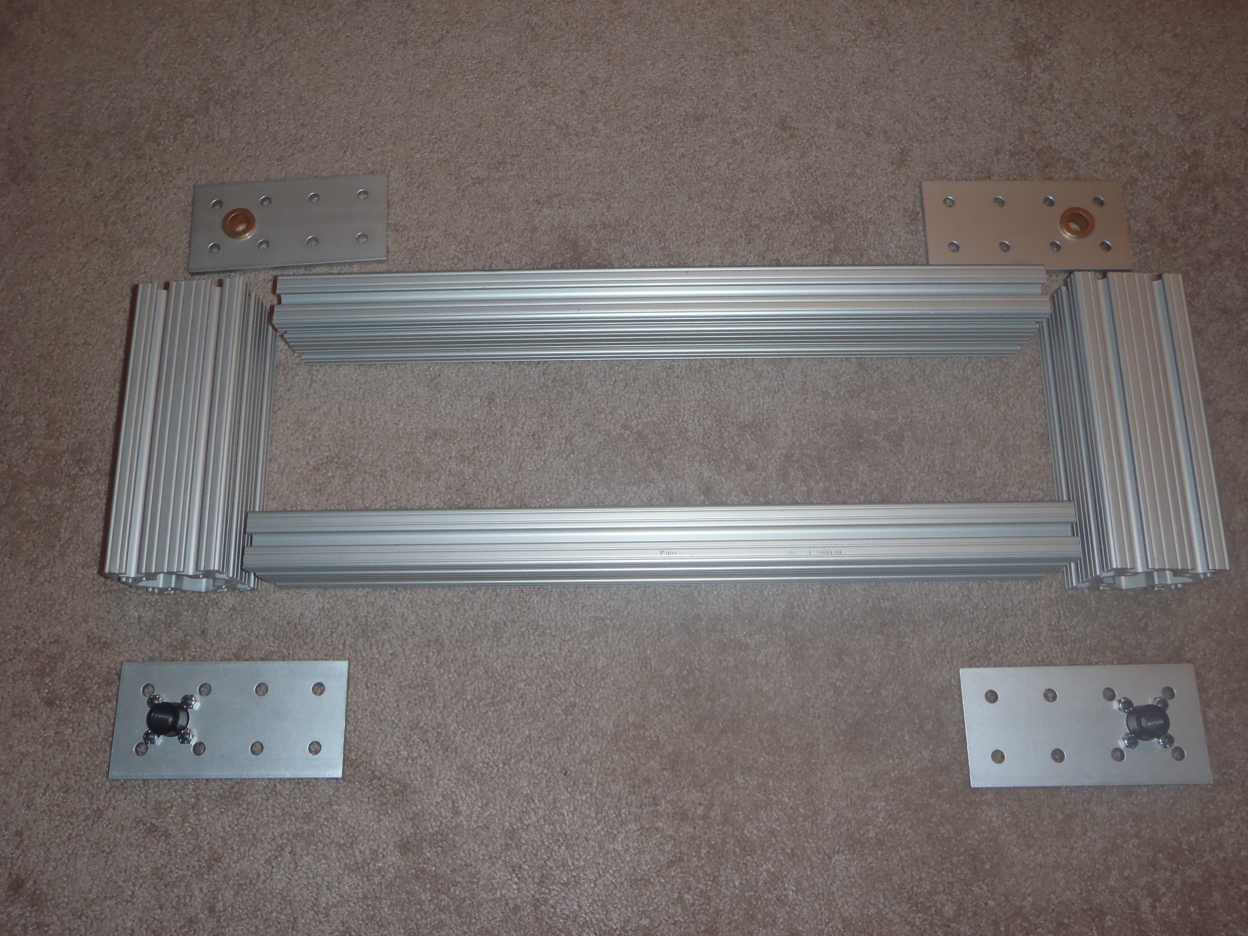
I did a lot of reading and redesigning. I started collecting parts for the new machine. I was lucky and salvaged some linear rails and some 3"x3" aluminum extrusion. I designed a machine around the parts I had. This was the first version of my design.
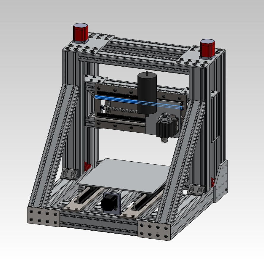
Then I change the z axis design. I decided to have two motors and use the software to sync them.
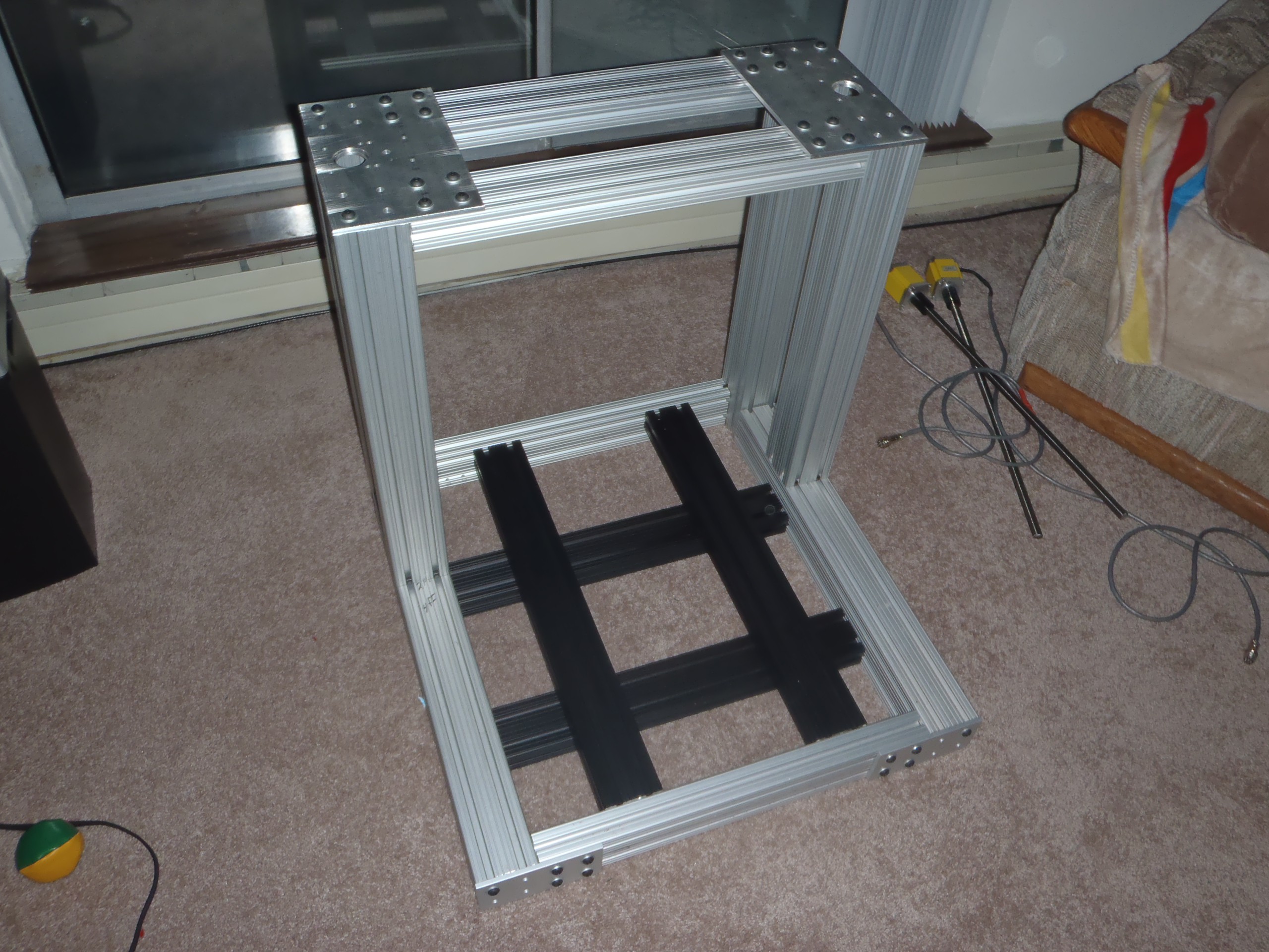
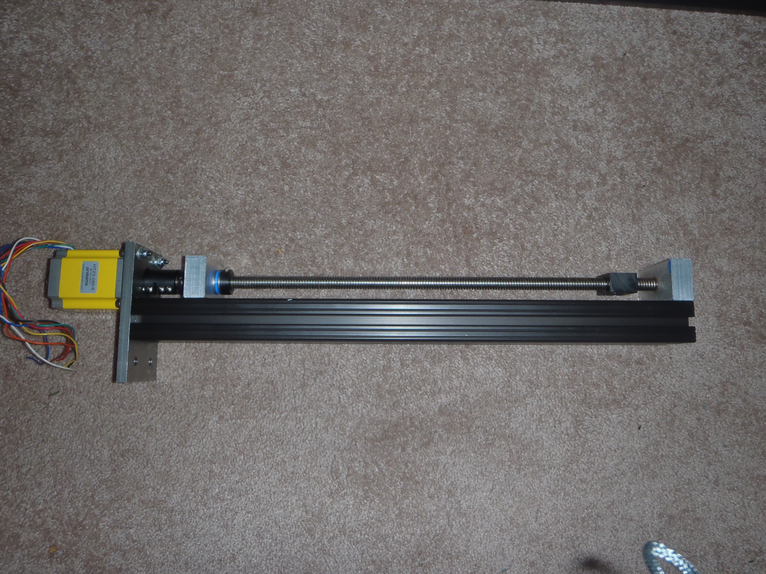
Then I started building it. WOW. I did not realize just how much work there was in this design.
-
Previous Version
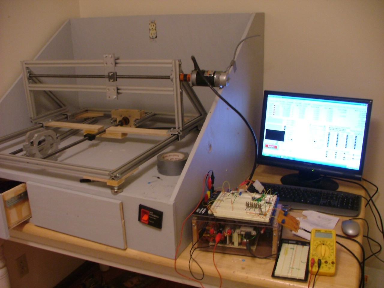
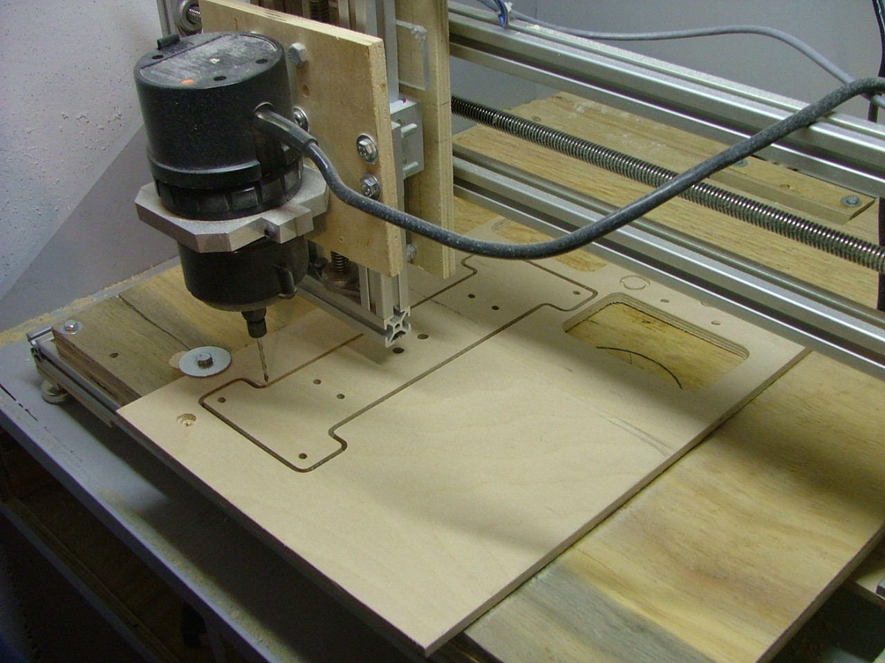
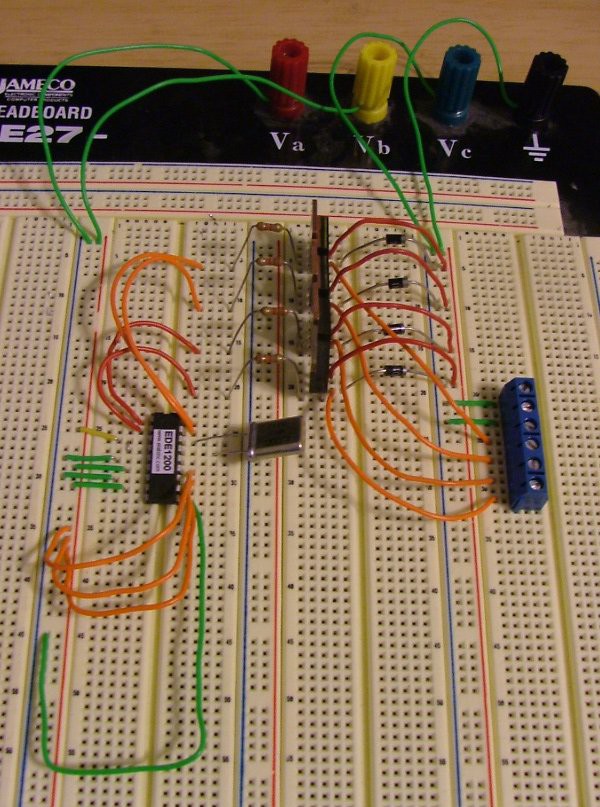
09/15/2015 at 03:41 • 0 commentsI have been working on this project for a long time. Several years ago I build a cnc router using 1" aluminum extrusion, the plastic bearings that slide over aluminum extrusion and a palm router. It was okay and I learned a lot. The biggest problem was that the frame was not very rigid and the flex in the frame made it hard to cut anything very accurate. The cheap bearings were also a problem. But I learned a ton. The whole things was my first real cnc project and I had not done much machining. I built my own stepper motor drivers as well. I was a poor college student and had to save money anywhere I could. When I moved I salvaged what I could and scrapped the rest.
 jupdyke