Andrew Starr
-
Data Multiplexer
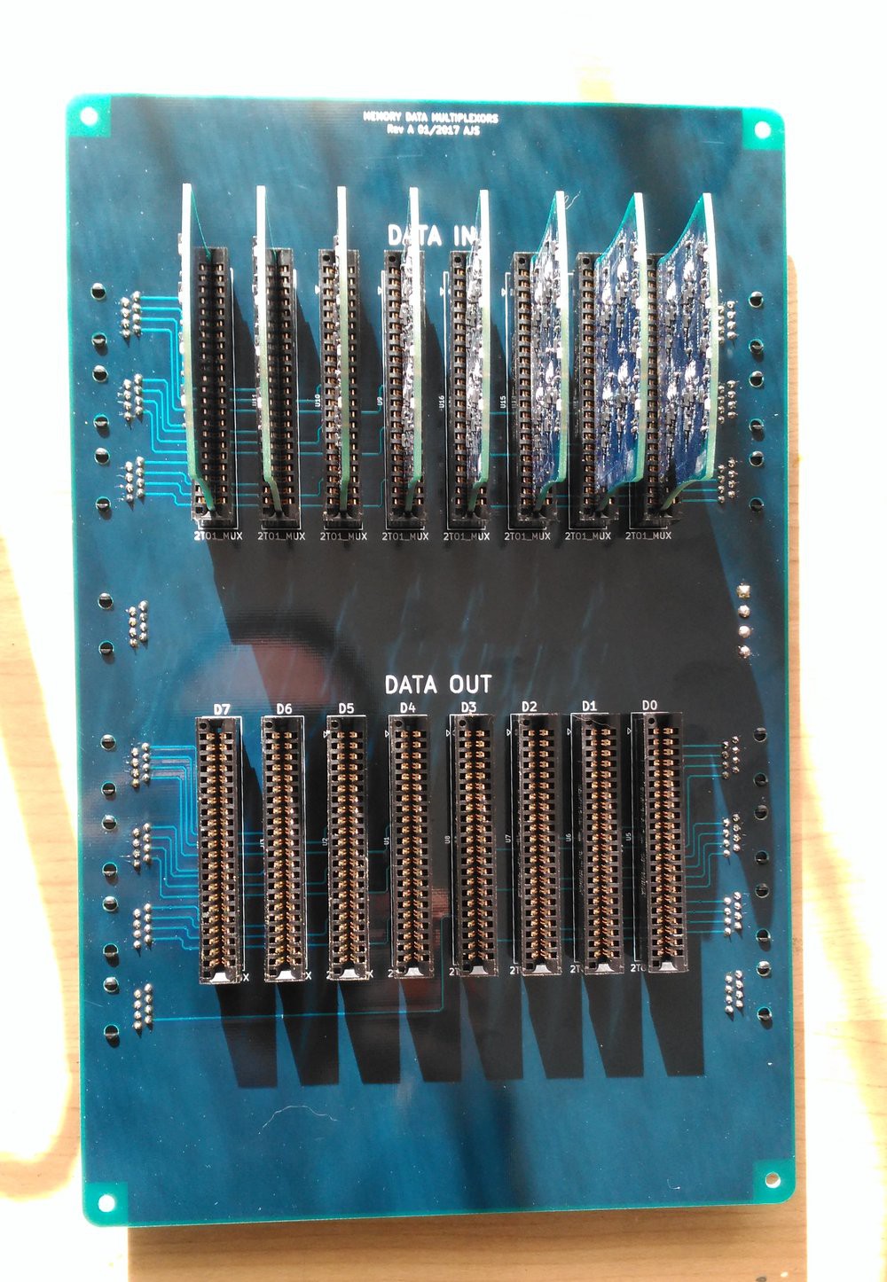
09/30/2017 at 04:29 • 0 commentsThe Data Multiplexer board is complete, and partially populated with modules. Its job is to select between accumulator and manual program data as the source for the memory data in, and select between memory data out and input port as the source for the accumulator and AREG mux.
![]()
I've run out of 2-to-1 mux modules, and need to make some more.
![]()
-
Program Counter Up and Running
09/04/2017 at 09:31 • 0 commentsAfter a exorcising a few gremlins (a diode around the wrong way, and a couple of unsoldered(!) joints), the program counter is working. As usual, here's a blinky video. The counter resets, counts up to 63 (i.e. the complete address space), then address values 0x15 and 0x2A are loaded a couple of times. MSB is top right, LSB is bottom left:
It's interesting that the camera autofocus has a few burps. I guess the LEDs are putting out a fair amount of infrared!
-
Program Counter Completed
08/27/2017 at 01:10 • 4 commentsThe program counter (a presettable 6-bit up-counter) has been completed:
![]()
Testing in progress...
-
Address Register Installed
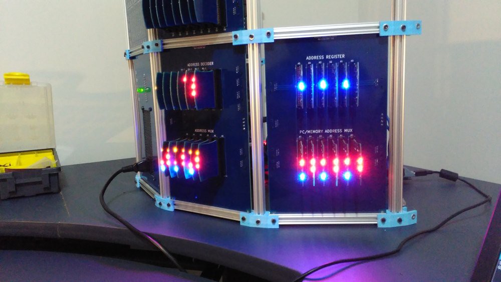
06/08/2017 at 09:40 • 1 commentThe Address Register panel has been installed:
![]()
The Address Register latches a 6-bit address from either the FC memory or the Program Counter. The output of the Address Register goes to the Address Mux/Decoder installed previously. Here's a short video of them working together:
Next up: the Program Counter
-
Address Mux/Decoder Completed
05/24/2017 at 09:13 • 2 commentsSee it cycling through the address space:
The bottom section multiplexes between 2 address sources: the address register and a manually-set address. The top section turns the selected address (blue lights) into a row/column selection for the memory (top right yellow lights).
I need some power splitter/extender cables before I can connect it to the FC memory, that's a project for this weekend.
Next panel: the address register itself.
-
Address Multiplexor and Decoder
05/06/2017 at 04:37 • 4 commentsThe next board to be added to the system - it selects between Address Register and Manual Address entry, and converts the selected address to Row/Column selection in the core memory. Pictured here with 6 partially-complete 2:1 mux modules yet to be installed:
![]()
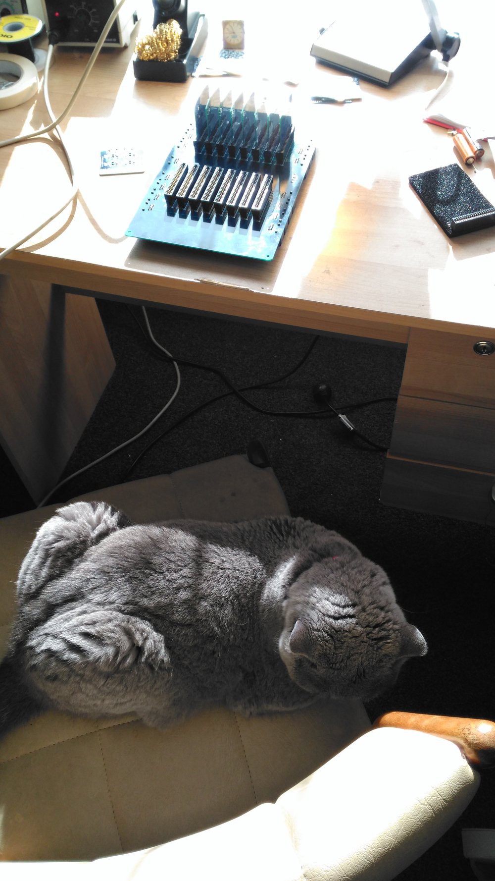
Note that all components get a liberal application of cat hair before installation.
-
Ch-ch-ch-ch-changes
04/12/2017 at 09:01 • 6 commentsAn architecture and name change: the T-1 is now the ED-64, and it is no longer a stack machine. The changes were made for several reasons:
- I decided I really wanted to be able to load programs into the memory manually from the operator panel, and the Harvard architecture of the T-1 (and 10 bit program word) wouldn't allow that.
- For an 8-bit word formatted [Opcode][Address], a 2-bit instruction width means a 64-byte address space. Since I am avoiding multi-byte instructions, that means I only need to complete a single 64-byte core matrix (which I already have).
- Only 4 instructions drastically simplifies the control logic and ALU, while still allowing enough complexity to do interesting things.
- I got bored with the 'T-1' name!
-
Emulator Shield Built
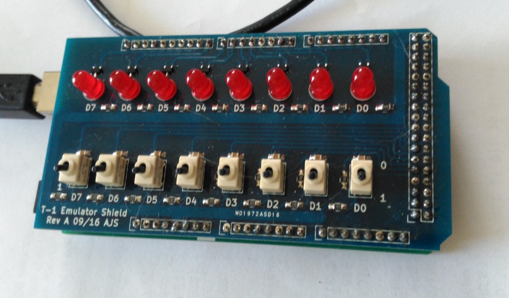
11/18/2016 at 22:50 • 0 commentsThe emulator shield is done:
![]()
I've written a program in T-1 assembler that simulates rolls of a dice. It uses a 32-bit Fibonacci linear feedback shift register to generate a pseudorandom bitstream, which is sampled 3 bits at a time to produce a pseudorandom number from 1 to 6 (0 and 7 are discarded):
The 8-bit input port is just used to generate a delay.
I'll upload the code soon.
-
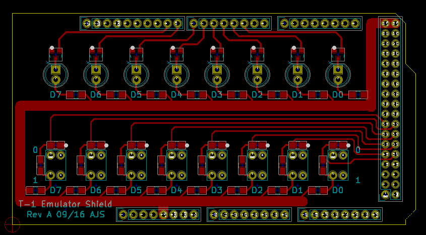
Arduino Shield for Simulator
09/14/2016 at 06:55 • 0 commentsI've designed a shield for my Arduino Mega 2560, that will provide the input and output ports. Once plugged in, the simulator (emulator?) will be able to do real-world I/O. Not much to it, just 8 LED drivers and 8 debounced SPST toggle switches:
![]()
-
Some Housekeeping
09/13/2016 at 09:01 • 3 commentsJust a minor update - I have done some 'simplification': halved the instruction set to 8 instructions total, and reduced the ALU to 4 functions. This will allow a significant reduction in the amount of hardware I'll need to make, while still allowing meaningful programs to be written. I'm also taking some inspiration from the Kenbak-1 - the I/O has been reduced to one input and one output port of 8 bits each. If this seems extreme, recall that the T-1 is more or less an 'art project' - I'm not trying to replace a desktop PC.
And there's always I2C/SPI :)
ED-64: A discrete 8-bit computer
ED-64 will be an 8-bit computer built with discrete components, and will feature a ferrite core memory (documented as a separate project).