This project is a subproject of #Ion wind loudspeaker experiments
The main idea of how to make it was: I need to place resistor joints in points in space that have the potential equal to the potential of the joint dictated by resistances. Flat plate capacitor is a good example of a system, where potentials are easily predictable. So, I decided to embed the chain of resistors into a flat plate capacitor.
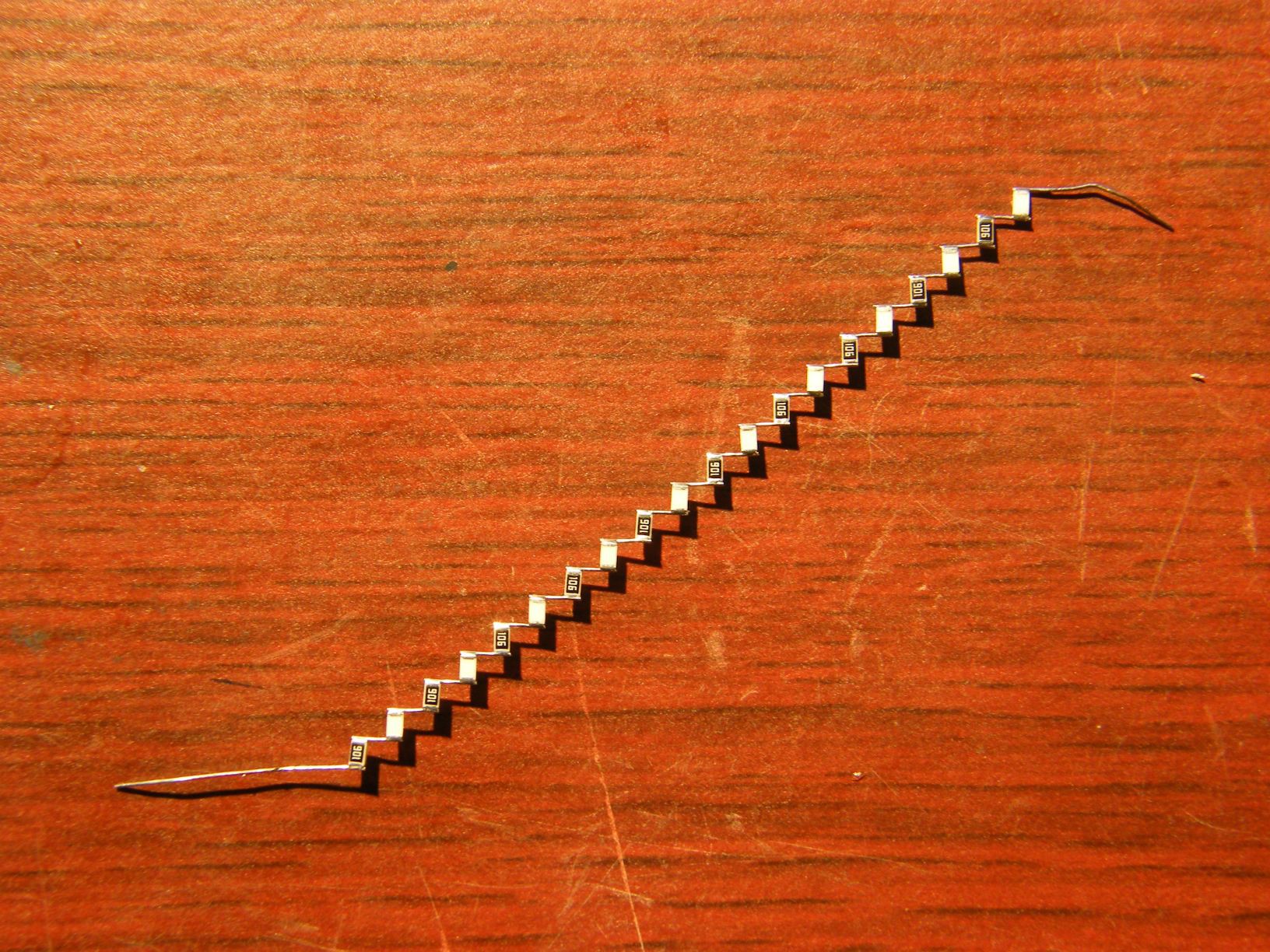
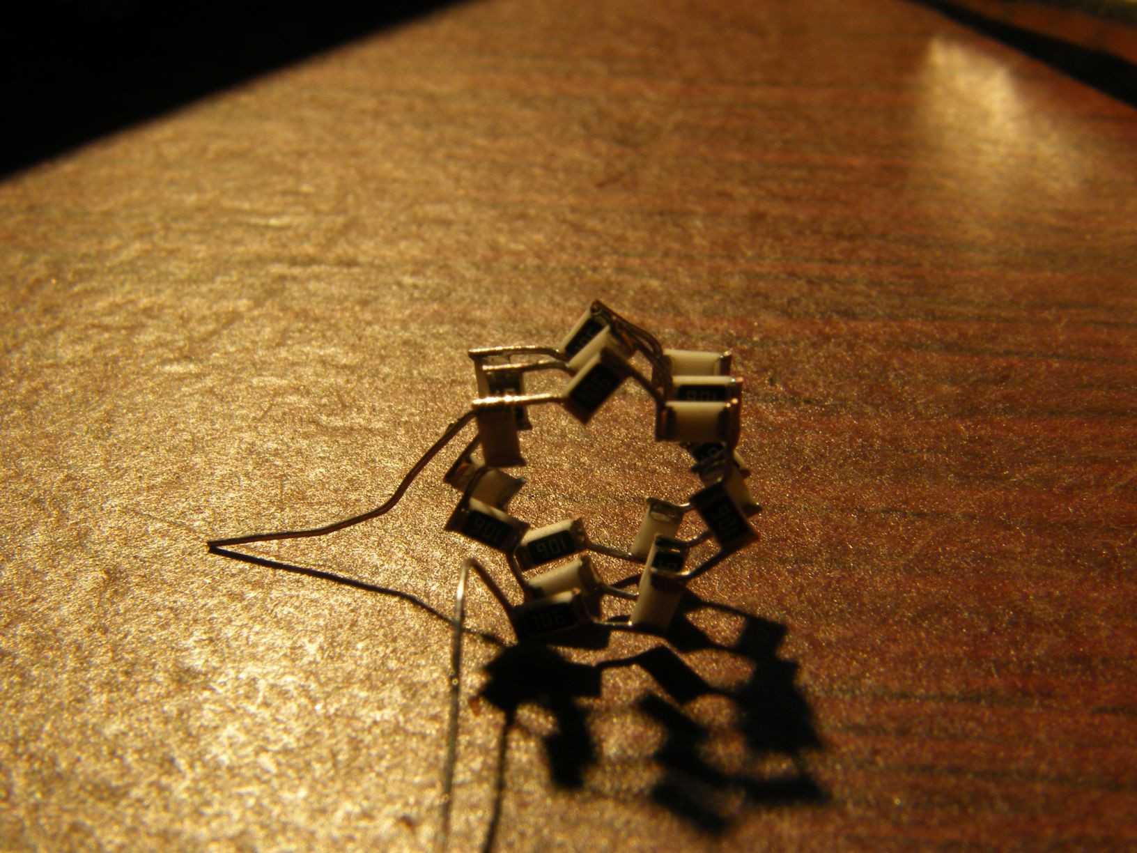
Chain of resistors is long; yet, a capacitor should be reasonably short, otherwise I would have to make the plates huge. So, I decided to coil the chain of resistors. On the photo, the final layout of the divider before placing into a shield, is shown.
Coaxial wire is soldered to the 100k resistor. The chain of 20 10M resistors (0805) is coiled between the plates of a flat capacitor formed by two coins. Compensation capacitor is to be connected later, at the other end of the coax cable.
Then, I used a metal cup as a shield, and potted everything with hot snot (thermal glue)
Results are quite awesome. But unfortunately, it was so long ago, I can't remember the frequency of the square wave that was used for testing (I suspect is was about 10kHz)
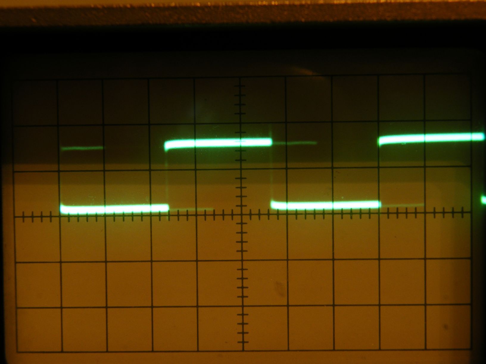
So that's it.
In the end, I got a working amplifier for my ionic sound experiments =)
Specs
Sorry, not much confidence here.
Bandwidth: I think it should be no less than 1 MHz. But I didn't measure it properly.
Division ratio: 2000:1
Input resistance (DC): 200 MOhm
Input capacitance: about 2 pF
Max voltage: 14 kV continuous, up to 30 kV briefly.
The main enemy here is heat. My intuition tells me that it should work as long as the power dissipation on the resistor chain is below about 1 watt. This is where 14 kV figure came from.
What can happen due to heating?
First of all, the glue will start melting. That isn't a problem, as long as the whole thing doesn't heat up to the point the glue will start leaking out. This is unlikely.
Next, the glue will start bubbling near the resistors. That IS a problem, it can lead to internal arcing and destroy everything.
Next, solder will melt, and the resistor chain will fall apart. The place where it snaps first will suffer arcing, which may eventually kill all the insulator. Although it may end up ceasing to function at DC, but still working well at AC thanks to capacitive part of the divider.
I did try applying 40 kV to it briefly. All I got was a huge spark from the probe to the shield across the air. Thermal glue is doing good as an insulator ;-) .
 DeepSOIC
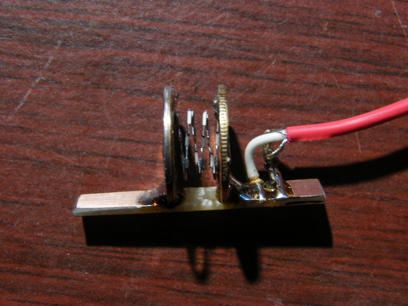

 Place the coil between two plates.
Hmm… I need a high-voltage probe (that goes higher in voltage than the Tektronix one Protospace has). This looks like a good one to build :)