rawe
rawe-
mpp temp. drift compensation
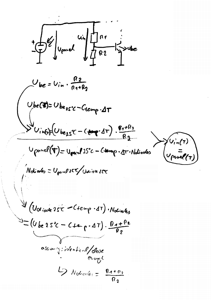
06/24/2014 at 12:31 • 0 commentsjust for completeness... yes, temperature drift of solar panel (so MPP voltage) can be compensated by the transistor in the input-voltage-regulation-loop, at least if forward voltage, temp. coeff. and temp. diff. are the same for that transistor and the panel (which is not the case for the real application, unless I hand-pick the transistor and couple it closely to the panel):
![]()
-
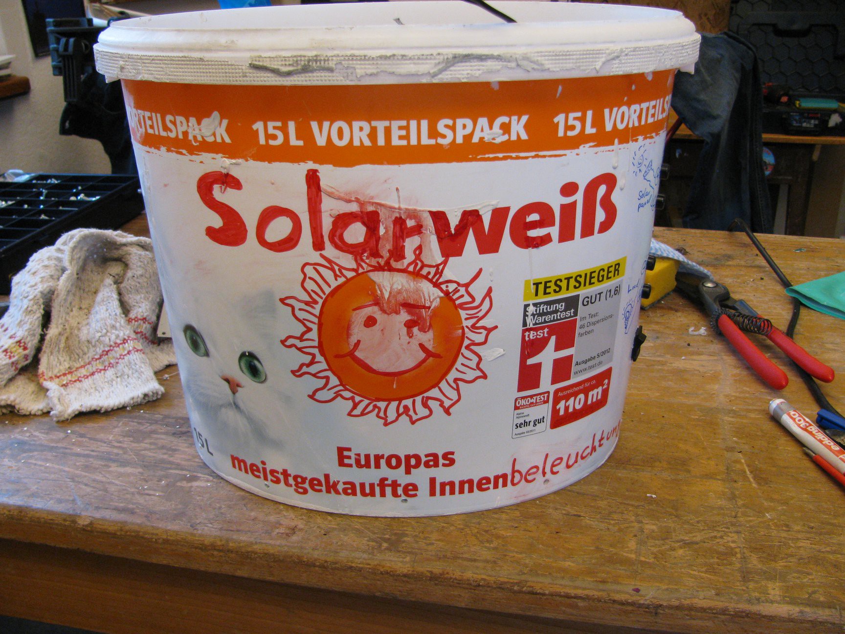
Enclosure: Solarbucket
06/10/2014 at 08:11 • 0 commentsA paint bucket, with some modifications, makes up a nice enclosure for the battery and electronics.
![]()
![]()
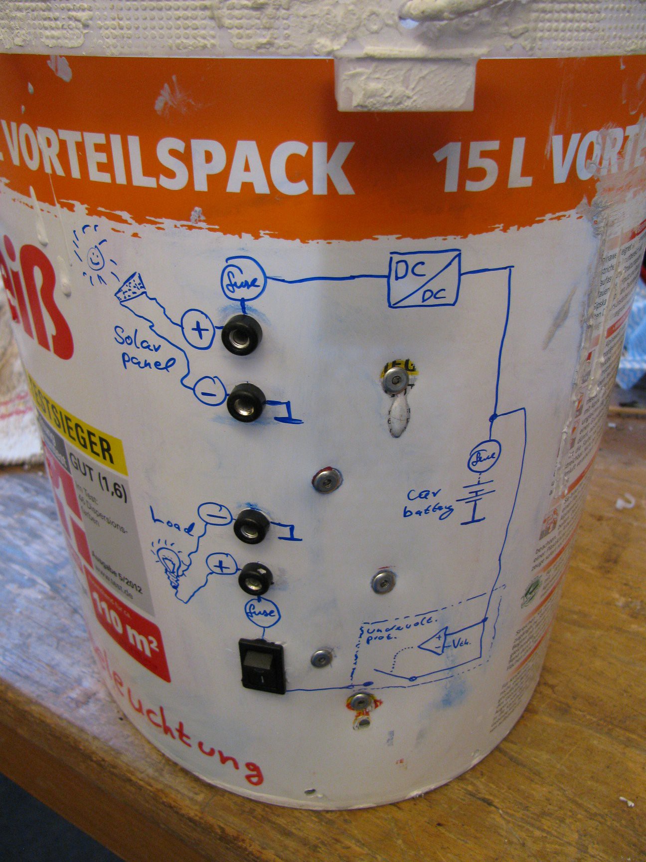
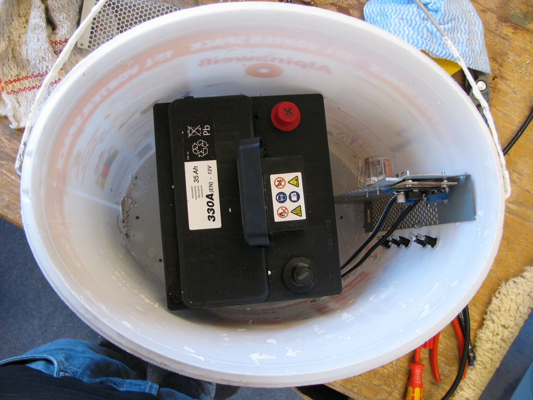
A 35Ah battery is held in place with an L-shaped metal part originating from an old old SCSI flatbed scanner power supply. As it is made of perforated metal, it is ideal to mount the electronics on there. The metal part is mounted to the bucket with rivets.
![]()
Holes were drilled in the bucket to let moisture out. I don't plan to overcharge the battery but if it does by some reason, the fumes should have a way out, too.
Front-panel-mount-type fuse holders and battery terminals are ordered and should arrive in some days...
-
lantern mount / test run (/w PSU)
05/20/2014 at 21:33 • 0 commentsDouble ferroules and short 30cm pieces of wire connect the single lanterns. The whole construction is mounted with zip ties.
As the front bar of the awning got a slot to hold the fabric, it is possible to wrap a zip tie around the wires, put the seal/fastener of a second zip tie on the attached one and latch the seal/fastener in the front bar slot:
![]()
![]()
For the first test run, an antique power supply does the supply job until the battery is ready:
![]()
With only 6 LED modules it is almost too bright, so I won't add more. This lanterns are there to create a nice atmosphere/mood and provide enough light to easily see each other and stuff on the grill, not to mark an airplane runway.
![]()
Next step is to integrate the charge controller, undervoltage protection and car battery in one old paint bucket, which will act as housing/weather protection, add connectors and see how it performs.
-
measuring U/I and U/P charts of unknown solar panel
05/10/2014 at 14:14 • 0 commentsFinally, today is a day with sunny weather + some hours of free time :D
Question: At which voltage should I use my (unknown type) solar panel to get maximum power out of it? Is it really that worse if I use it a few volts above or below? Is it worth the effort to use a buck converter?
Test set-up
The following picture shows the measurement setup:
![]()
The solar panel (mounted outside) is connected to an electronic load (Litronic 9121, center of image) with monitoring output and modulation input. The monitoring output is connected to a scope (Rigol DS1052E, right hand sinde of image), which records the two channels (voltage and current) to an usb stick (.csv file).
The signal generator (Philips PM5108L, left hand side of image) creates a triangle wave from 0V up at about 40Hz (high enough for fast "frame rate", low enough to not create huge measurement errors). The triangle wave controls the electronic load current. The higher-voltage higher-z output of the signa generator is connected to the ext-trig input of the scope, to trigger reliably.
![]()
Of course, this can be done by hand (power potentiometer as load and multimeters to measure U and I), too.
It is really interesting to see the output curve, based on the birghtness change when clouds pass by:
As my Thinkpad T30 does not like plotting charts out of spreadsheets with thousands of items in it, plus open office does not like the scientific notation used by the rigol scope (only if I switch locale settings...), the following python script was used to compress the data down to fewer entries and do the power calculation.
#!/usr/bin/env python
import csv
import sys

def powercurve(fname_in,uifactor,shorten,fname_out):
    with open(fname_in, 'rb') as f:
        reader = csv.reader(f)
        rowctr = 0
        voltage_avg = 0.0
        current_avg = 0.0
        power_avg = 0.0
        out_list = []
        for row in reader:
            if row[0] != "X" and row[0] != "Second":
                rowctr+=1
                voltage = float(row[1])
                current = float(row[2])*uifactor
                power = voltage*current
                voltage_avg+=voltage
                current_avg+=current
                power_avg+=power
                if rowctr%shorten == 0:
                    voltage_avg/=shorten
                    current_avg/=shorten
                    power_avg/=shorten
                    dataset =[voltage_avg,current_avg,power_avg]
                    out_list.append(dataset)
                    voltage_avg=0
                    current_avg=0
                    power_avg=0

                    print dataset

    with open(fname_out, 'wb') as f:
        writer = csv.writer(f)
        writer.writerows(out_list)

if len(sys.argv) <3:
    exit()

powercurve(sys.argv[1],2,32,sys.argv[2])
Results and discussion
Some spreadsheet-chart-voodoo later, the following chart pops up:
![]()
The blue-ish curves correspond to the left Y-axis and show the current. The red-ish curves correspond to the right Y-axis and show the power. One current- and one power-curve belong together (ordered by color intensity).
The ambient temperature was at about 25°C. The different intersection points with the X-axis may indicate, that the temperature of the panel was a bit different for the single curves (there was strong wind which may have cooled the panel?).
For all the curves plotted, maximum power can be achieved at about 14 Volts. There is a big range of tolerance, +/- 1V, where the output power does change by a small amount only.
If the step-down had an efficiency of 100%, I would get approx. 0.5W (approx. 6%) more out of the solar panel with it, if the battery would be at 11V and the sun would shine "max" (lightest curve). As this is the situation where I would benefit from the step-down the most, it is propably not worth the effort at all for this panel. Other panels with higher voltage would benefit much more from the step-down. As I already built the circuit and it provides some level of charge control, I'll use it (maybe I'll switch for another panel or add a second one in the future).
-
LED lanterns
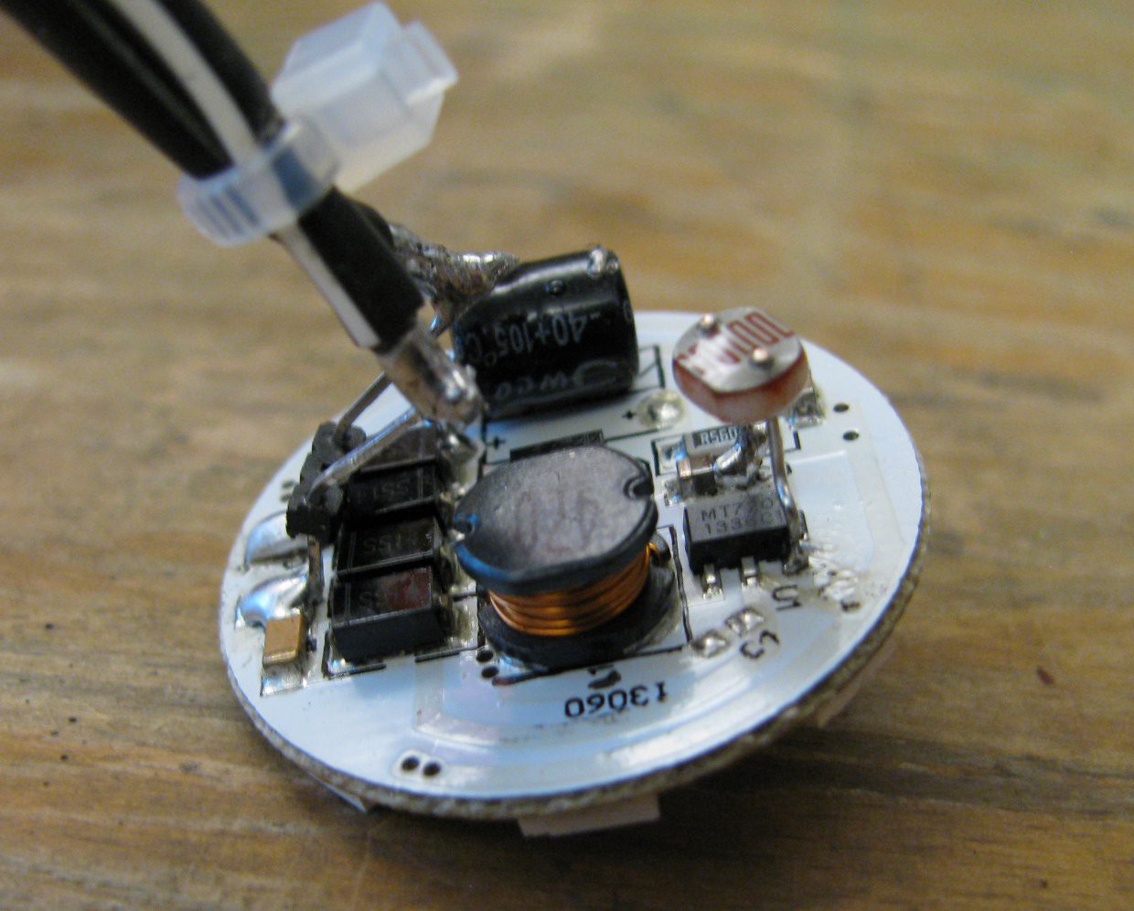
04/30/2014 at 17:21 • 0 commentsThe build process of these is quite simple, parts count is at a minimum, assembly is fast and price per lantern is approx 5 Euro.
The LED module (see parts list) needs two modifications:
- The power pins are desoldered, bent around, and soldered back in place at a different angle, to allow wire attachment from above the module.
- A light sensitive resistor is attached at the current control pin of the switching regulator towards ground, pulling this pin low as long as light shines on the photoresistor. As the control pin is an analog pin and provides an internal pullup, this one-part solution provides slow "fade in" if sun falls. I can't wait to see the feedback loops/interactions between the different lanterns happen :D To minimize the chance of randomly blinking LED lanterns, the photoresistor is aligned up while the LEDs shine down.
![]()
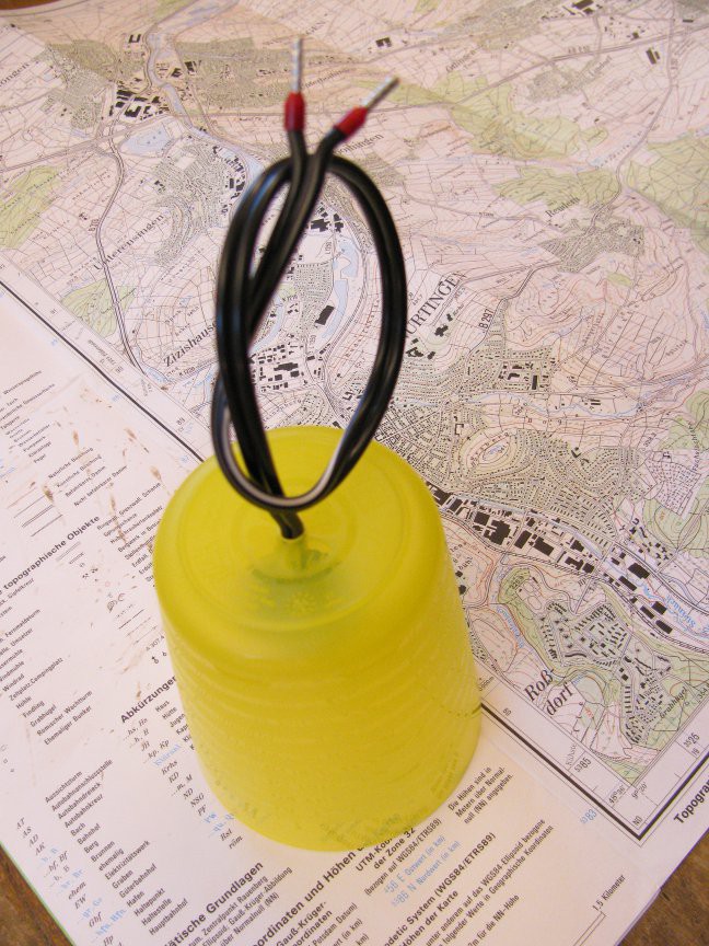
A yellow Ikea plastic cup was chosen for the first epic lantern of doom™ ever made. A drillpress is nice to make a centered hole in the cup (there is even a pattern that helps to find the center).
![]()
Ok, so how does this photo resistor hack perform?
Youtube videos are broken on hac.io, right now...Video 1 Video 2
To prevent water from dripping down into the cup, it is necessary to add some hot glue or similar to cover the drilled hole.
-
panel mount
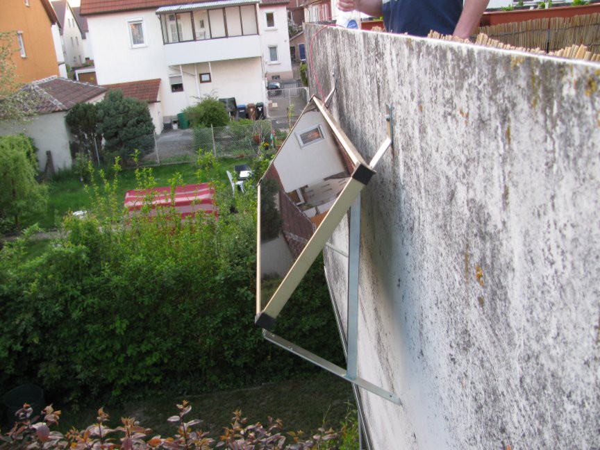
04/24/2014 at 21:49 • 0 commentsCheap robust (8Eur per piece) L-Type shelf brackets (30x45x3cm) were slightly modified.
The last few centimeters of the long arm were bent with the help of a vice and a hammer:
![L shelf brackets]()
...one additional hole per bracket with the right distance makes the parts fit:
![]()
The whole construction fits nicely on the outside of my balcony railing. Two original mounting screws for the railing were replaced with longer ones, now holding the solar panel in place, too.
![]()
The mounting angle is 45°-ish (30° would be better for overall collected energy). This means collected energy in summer when sun is high is not as good, but in the other seasons where the sun is located lower, more energy is collected, plus leafes or snow have a higher chance to get off the panel.
-
battery charger /w step-down
04/16/2014 at 10:04 • 0 commentsOverview
The battery charge controller should do two things: get as much power out of the solar panel and switch off if the battery is full.
To get maximum power out of a solar panel, it is necessary to use it in (or at least near) the MPP (maximum power point), normally an MPP-Tracker algorithm would do this.
Here is a sketch of the U/I relation of a solar panel and the P/U relation:
![]()
Output current stays about constant as long as the voltage on the panel is below a certain point. But as power equals current times voltage, it makes sense to use the panel in the upper range where P is max.
I am too lazy to build an own stepdown controller with custom regulation, mpp tracker algorithm etc (see here for a nice one by a guy who does this in his job, too), so I'll go the easy route based on this concept.
It does no software MPP tracking, but still provides better efficiency than a simple linear regulator (or even a series diode). Plus these LM2596 step-down converter boards are really cheap (2 eur per board) and I got some of them in my parts bin.
![]()
This test setup with 2k pot / 47k voltage divider to base of bc547b with 220k pullup works for holding the input voltage above a certain point.
![]()
With further modification it fits the application:
![]()
The copper board is soldered to GND of the DCDC board and acts as additional heat sink. It took two soldering irons set to 450°C to solder that board sandwich together, but the caps seem to have survived it. The additional board got holes to mount this construction in a housing. I've soldered the in/out wire GND/"-" directly to the GND contact of the switching regulator for cleaner wiring.
The additional NPN transistor is located near the heat producing elements, which is not ideal, due to temperature dependency (ideal would be same temp. as solar panel). The ideal location for this circuit would be near the solar cell. Calculations or maybe a simple simulation have to show if this matters that much.
Control loops
In normal (unmodified) schematic, the step down converter just does the following to regulate the output (simplified, there may be a nested current control loop, depending on regulator, which I omit here):
![]()
...with resulting output current:
![]()
With the additional parts, the schematic forms nested control loops:
![]()
As long as the input voltage is about a set value, the buck converter just does its normal work and regulates the output voltage. As soon as the input voltage gets too low (because the solar panel can't provide that much current), the outer control loop kicks in and limits the current by disabeling the output:
![]()
*ADD MEASUREMENTS FOR DIFFERENT SCENARIOS HERE*
Temperature compensation
As the MPP is temperatue dependent (a solar panel is just a bunch of odd mutant ninja diodes, so shockley equation applies), it makes sense to add at least some degree of temperature compensation to get out more power:
![]()
The forward voltage of a diode changes with some mV/Kelvin (usually around -2mV/K for a silicon one).
As a solar panel consists of a bunch of diodes in series and this temperature dependency applies to every single diode, the temperature dependency of the whole panel sums up to
Upanel,tempdep = Uref - Ctemp * Ndiodes * deltaTemp
The circuit sketched above regulates its input voltage to a point depending on the base-emitter voltage of the BC547B on its enable pin. This voltage is generated from the input by a voltage divider, so:
Ube = Uinput * dividerfactor ; Uinput = Ube / dividerfactor

Ube = Ube,ref - Ctemp * deltaTemp

Uinput = (Ube,ref - Ctemp * deltaTemp) / dividerfactor
...with...
Uinput = Upanel,tempdep
...this resolves to...
(Ube,ref - Ctemp * deltaTemp) / dividerfactor = Uref - Ctemp * Ndiodes * deltaTemp

(Ube,ref - Ctemp * deltaTemp) / (Uref - Ctemp * Ndiodes * deltaTemp) = dividerfactor
***BLABLA put some more thoughts in this and plot a nice chart, plus find a way to show nice formulae on hac.io, and re-calc the whole thing on paper. Ascii monospaced text is just a pain to think math formulae in *
With apporx 2mV/Kelvin base emitter diode and a gain of approx 25 this leads to 54 mV/Kelvin input voltage temperature dependency. With a solar panel with 29 cells this would lead to 54mV/29 = 1.8mV/Kelvin per cell, which is quite reasonable. With additional base resistor of feedback loop transistor this could be further adjusted...
...
-
undervoltage protection and automatic dusk light switch
04/14/2014 at 21:30 • 0 commentsThe "undervoltage protection and dusk light switch" has two purposes:
- It switches the load off as soon as a critical (low) voltage is reached.
- It disables the output as long as the solar panel still provides more than an adjustable voltage (e.g. by day it disables the attached LED lights).
There is no charge controller in here as it is a separate function. There are no fuses drawn here, too. Always use fuses if dealing with stuff that can provide enough power to burn or damage something... Also, there is no (required) flyback-diode for the relais coil drawn.
The circuit is designed with low parts count and bin parts reuse in mind, so it is by no means a perfect by-the-book circuit and may show bad design technique. Think of diode forward-voltage and its temperature dependency, relais hysteresis depending on part variation etc.
Here is a quick sketch of the schematic which shows the working principle:
![]()
Undervoltage protection:
The output from the charge controller is connected to the car battery by a power diode. A 10 volts zener diode (with current limiting 2k2 resistor in series) drives the base of an BC547B npn transistor. A second 2k2 resistor is in parallel with the base-emitter-path of the BC547B npn transistor. This reduces the sensitivity of the circuit to noise, but also reduces hysteresis (which could lead to oscillation). The base capacitor of a few µF dampens oscillations which could occur by the non-zero series resistance of the car battery, a fuse etc. as the transistor circuit provides negative, phase shifted (relais inductor coil) feedback with gain.
If the battery votlage goes high enough, current flows thru the zener diode and the base voltage of the BC547B npn transistor rises high enough that there is enough base current to drive the relais strong enough to switch on. Load connected.
If the battery voltage falls low enough, base voltage and current of the BC547B transistor goes down so the relais will switch off again. Load disconnected.
automatic dusk light switch
Assuming that the battery is fully charged, there is no or only a low load on the solar panel. This means it provides approx 20V (at least mine does). A solar panel is (within limitations) a current source with current depending on light level.
By driving this current thru a current-sensistive amplifier/switch (BC547B again...) and preventing the relais-driving npn transistor from switching on by stealing its base current, the logic function "if light level is above a certain limit, disable output" can be achieved.
To make the switching point adjustable, a potentiometer can be used to set the base current.
As the load on the solar panel increases (charge circuit tries to kick in as soon as battery voltage drops), the output voltage of the solar panel drops further (now by darkness and load). This mechanism provides positive feedback, so this time no oscillations should occur.
First test testup of undervoltage circuit:
![]()
...built on prefboard:
![]()
...provides the following Uin (CH1/X)/Uout(CH2/Y) relationship (sorry for the screenSHOT, I had no fat16 usb stick):
![]()
Hysteresis is just about 240mV with this circuit, which may be too less to avoid oscillation, based on the series resistance of the battery.
I've decided to leave the dusk sensing out of this circuit part for now, as the LED modules provide this function.
30W (=~240W halogen) LED balcony solar lanterns
summer is on its way and my balcony needs light to be summer-night party-ready