Close
0%
0%

Glowstick kinetics

Investigating the kinetics of chemiluminescent reactions using photometry.

Similar projects worth following
Exploration of the kinetics of chemical reactions is easy when the reactants and/or products can be measured directly. For instance, the concentration of coloured compounds is easily directly measured with spectrophotometry. Similarly, if a reaction consumes or produces small ions, conductivity measurements can be used for direct determination of electrolyte concentration.

The obvious method to investigate chemiluminescent reactions is photometry. The intensity of emitted light is then directly proportional to the reaction rate.

This project is a simple student friendly package for using the Linear CCD module in kinetic measurements of chemiluminescent reactions.

This project is really just a 'wrapper' for the linear ccd module so for details about driving and reading the TCD1304 refer to that project.


The following is a (very) brief introduction to reaction rates.

For a given reaction:

The reaction rate, v, is defined as:

many reactions have rates that follow the concentration of the reactants as:

However, this is a pure empirical relation and the reaction orders of A and B (n and m) cannot be deduced except by experiment (and to make matters worse, they may change with the conditions of the reaction).

When combining the two expressions for v, we get this differential equation:

Obviously we must ignore B (in the lab this is done by keeping its concentration constant). The reaction order for A, n,  usually takes the integral values: 0, 1 or 2 (but anything is possible). For the three "normal" values of n, the differential equation has the following solutions:


In a chemiluminescent reaction the light intensity, I, is proportional to the reaction rate so we can write:

By measuring I over time, one can essentially find a function that describes the reaction rate as function of time. If the reaction is "well behaved" ie. if the reaction order is either 0, 1 or 2, this function should be identical to the 1st derivative of one of the 3 solutions to the differential equation.

In brief, the reaction rate is:

  • constant, for 0th order reactions
  • an exponential function of time, for 1st order
  • a hyperbola or something (1/t²), for 2nd order

glow-scads.zip

3D-drawings (openscad)

Zip Archive - 2.49 kB - 03/11/2018 at 09:16

Download

  • Glow in the dark star (ZnS:Cu)

    esben rossel03/23/2018 at 10:54 0 comments

    Glow in the dark stars contain a phosphorescent pigment consisting of copper doped zinc sulfide (ZnS:Cu) or europium doped strontium aluminate (SrAl2O₄:Eu).
    It's super-easy to produce zinc sulfide, one simply mixes solutions of sodium sulfide and a soluble zinc salt e.g. zinc chloride:

    Zn²⁺ + S²⁻ → ZnS(s)

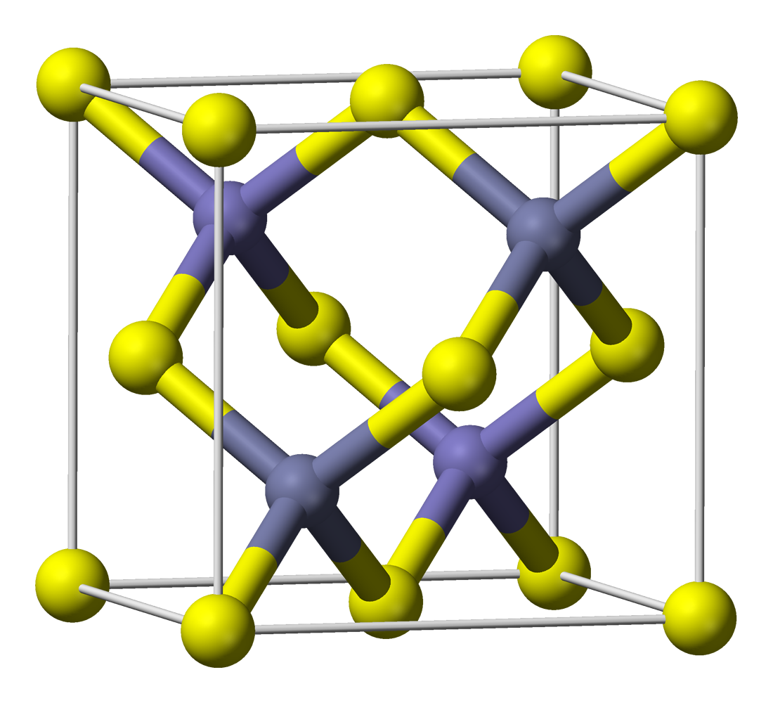
    However, merely precipitating ZnS in the presence of Cu²⁺-ions does not yield phosphorescent ZnS:Cu. Zinc sulfide formed this way has a zinc blende structure (it is zinc blende) and it has a crystal lattice as shown here (image stolen from wikipedia):

    The phosphorescent ZnS:Cu is first formed when the ZnS/CuS is heated to app 900°C under an inert atmosphere (or better yet, in an atmosphere of H₂S). In other words, it's not for kids.

    Zinc sulfide is a semiconductor and when doped with Cu, electron holes are introduced. When exposed to (near-)UV light electrons are excited to the conduction band, and when they relax and recombine with the holes, light is given off.

    The kinetics of the decay can be studied by following the light intensity over time. In this experiment the Linear CCD module's SPI firmware was modified to power an LED (Osram Duris E5) which was placed behind a piece of a glow-in-the-dark star situated just in front of the CCD. The LED was turned off immediately (app 7.5 ms) before data collection.

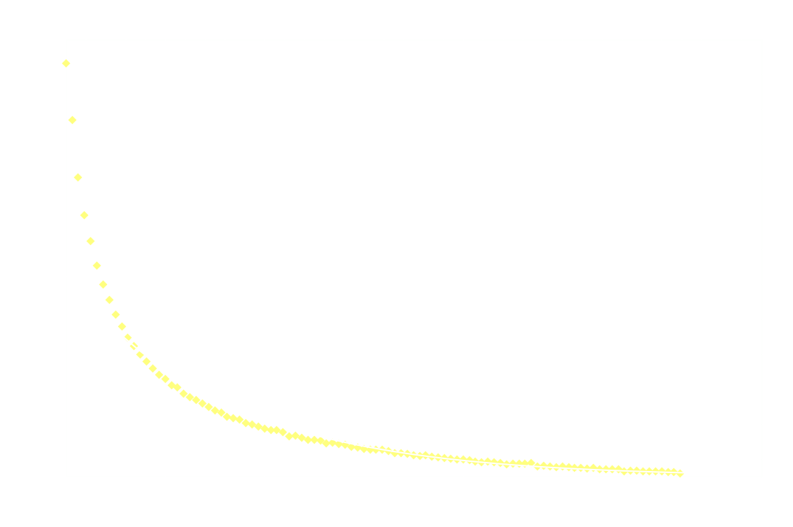
    The following graph shows the light intensity as a function of time:

    Surprisingly, the decay doesn't follow 1st order kinetics. The first 250ms it appears to follow 2nd order kinetics, as seen in the next graph:

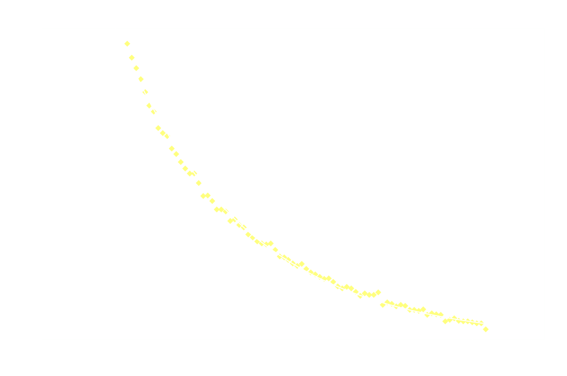
    Hereon after, it's back to 1st order:

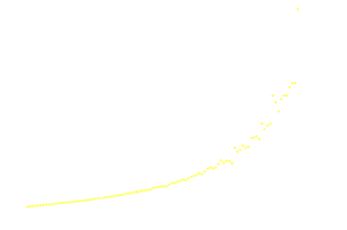
    And just for good measure, here's the 2nd order model on the entire dataset:

    Clearly 2nd order is not a good fit after the first 250ms.

    It's not the LED-phosphor playing tricks, the LED-emission stops almost instantaneously after it's powered off (at least it's so fast, that it doesn't interfere with the measurements).

    A similar investigation is presented in the following article, but the authors reach the opposite conclusion, that the decay is 1st order initially, and then becomes 2nd order:

    Experiments with Glow-in-the-Dark Toys: Kinetics of Doped ZnS Phosphorescence, George C. Lisensky, Manish N. Patel, and Megan L. Reich, J. Chem. Educ., 1996, 73 (11), p 1048

  • Lab-procedure (I) Glow sticks

    esben rossel03/10/2018 at 15:34 0 comments

    Glow sticks contain a diphenyl oxalate, hydrogen peroxide and a fluorophore, and a solvent of course.

    The general reaction between diphenyl oxalate and hydrogen peroxide is:

    The square shaped product 1,2-dioxetandione is not stable and immediately breaks down to CO₂:

    This CO₂ is produced in an excited state and will immediately relax by emitting a photon in the UV-range:

    The photon excites the fluorophore:

    which remits a photon in the visible spectrum:

    It's the fluorophore's emission spectrum that determines the colour of the glow stick.


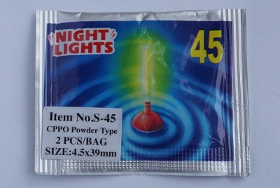
    In this procedure I'm using glow sticks for night fishing:

    Each glow stick contains a glass ampoule with ca. 70mg of this particular diphenyl oxalate (R is pentyl):

    and a fluorophor that could well be fluorescein.

    The glass ampoule is surrounded by a viscous liquid that my IR-spectrometer identified as dibutyl phthalate. The phthalate contains enough H₂O₂ that my fingers turned snow-white after brief exposure to it.

    Experimental:

    A glow stick was carefully cut open with a scalpel and the glass ampoule was removed and placed in a beaker and rinsed with acetone. The clean ampoule was broken in a new beaker and the content dissolved in a few mL ethyl acetate. The solution was transferred to a 10 mL volumetric flask, which was filled to the mark with ethyl acetate.

    Hydrogen peroxide (10 mL, 35%) was mixed with 30 mL ethyl acetate. After 2 min. of vigorous stirring the two-phase system was transferred to a separating funnel and the ethyl acetate was collected in a 50 mL conical flask. This yielded a solution of H₂O₂ in ethyl acetate with a concentration of app 2M (measured by titrating 200 µL of the solution in 10 mL 1M H₂SO₄ with 0,020M KMnO₄).

    1.5 mL of the diphenyl oxalate solution was placed in the spectroscopic cell, after which 1.5 mL of the H₂O₂ solution was added and the measurements immediately started (integration time 2000 µs, measuring frequency 1 Hz, measuring time 50 s).

    One will have to fiddle a bit with concentrations, integration time etc to get proper data, but worst of all also the base line.

View all 2 project logs

  • 1
    Step 1
    1. Build a linear CCD module (SPI-version)
      The 3D-printed CCD-box is for the LDO-version PCB (but the LDO part of the circuit does not necessarily need to be populated). Install a 1x6 pin header on the back of the board. [picture coming]
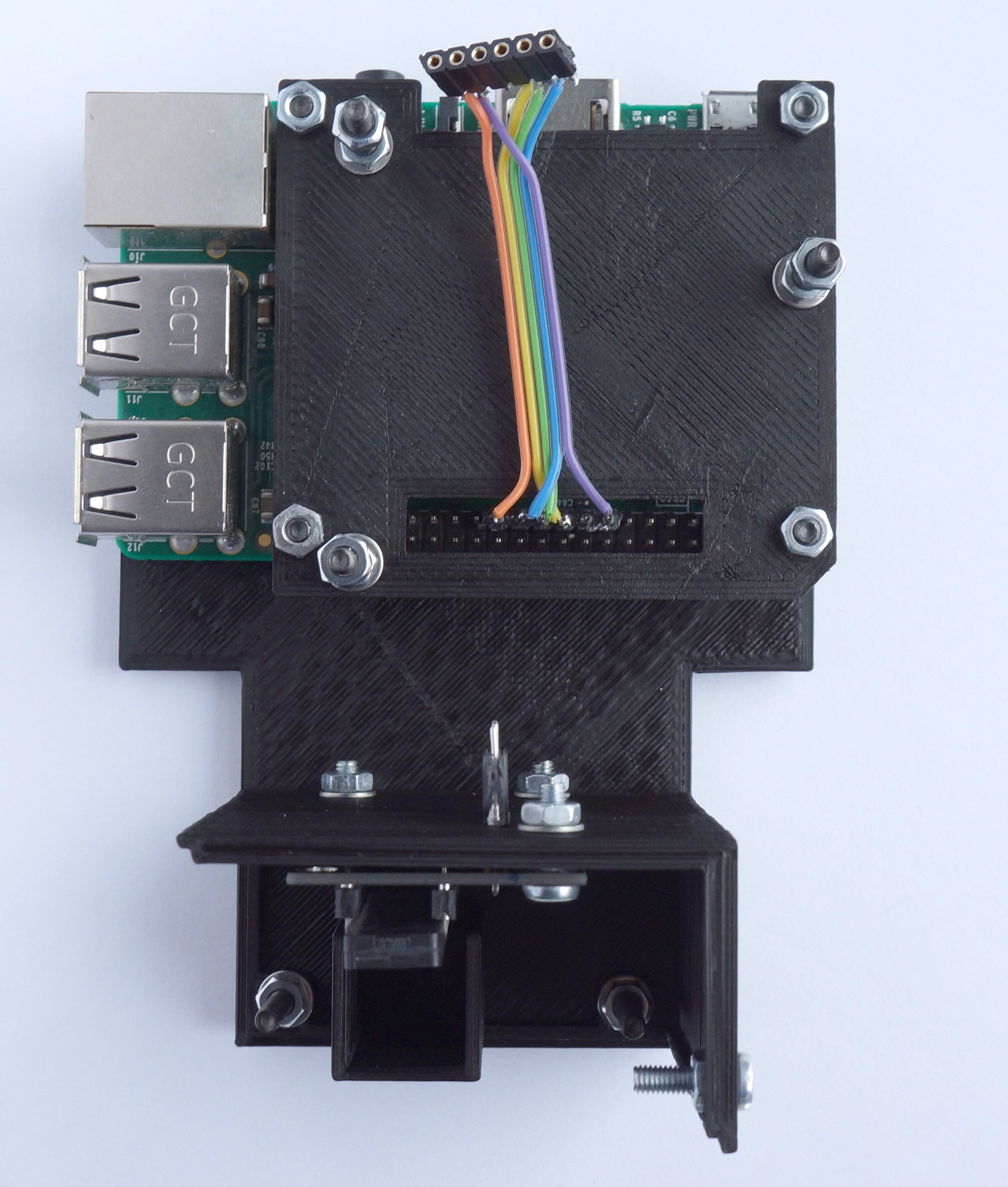
    2. Print everything (box for the CCD, magnetic lid for the box, base for the rpi, sandwhiched-layer between nucleo and rpi).
    3. Assemble the stuff:
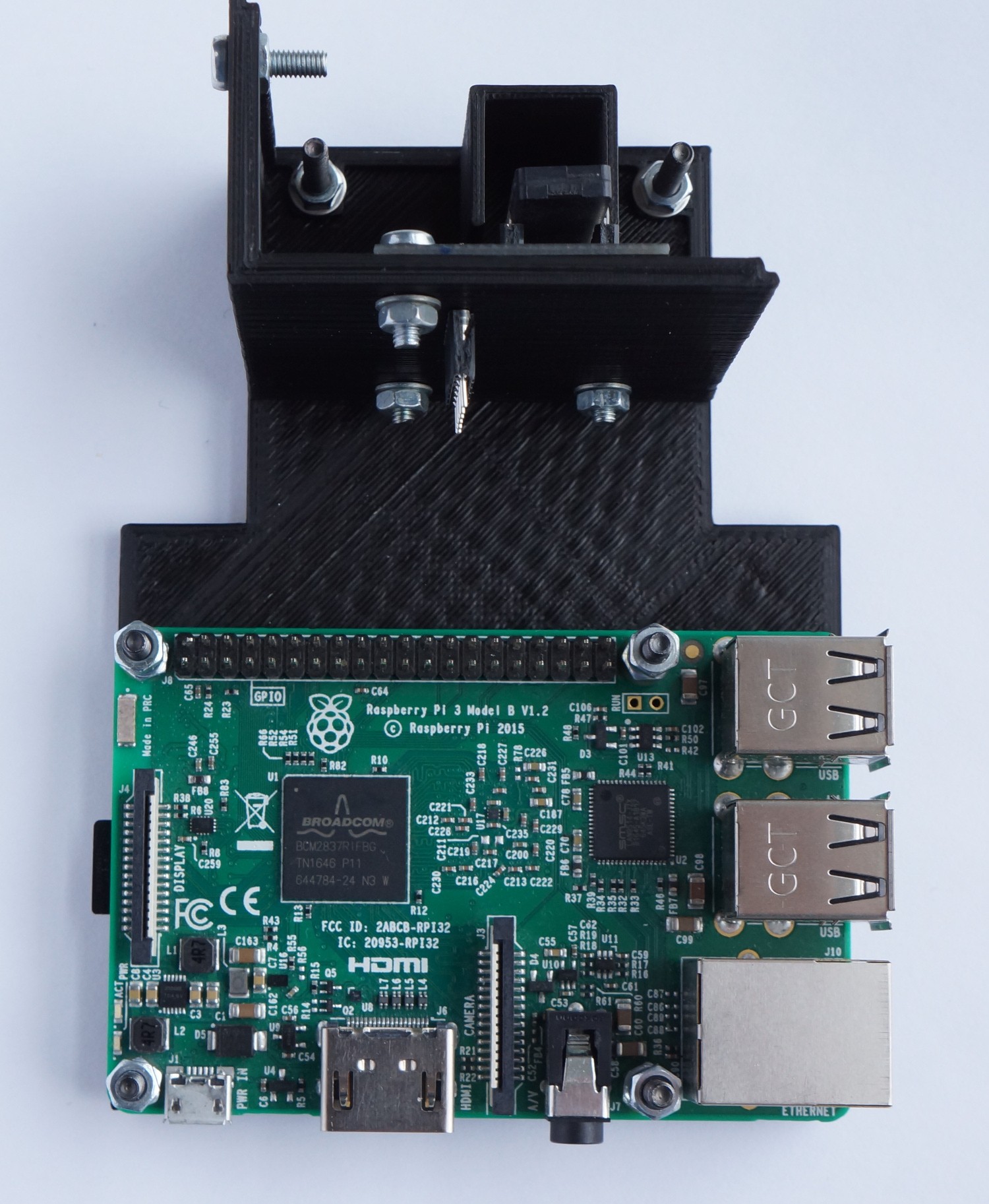
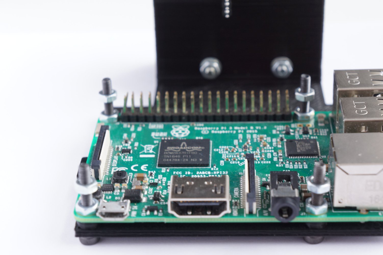
      Install rpi at bottom with 20mm M3 screws (the holes in the rpi may need to be expanded):
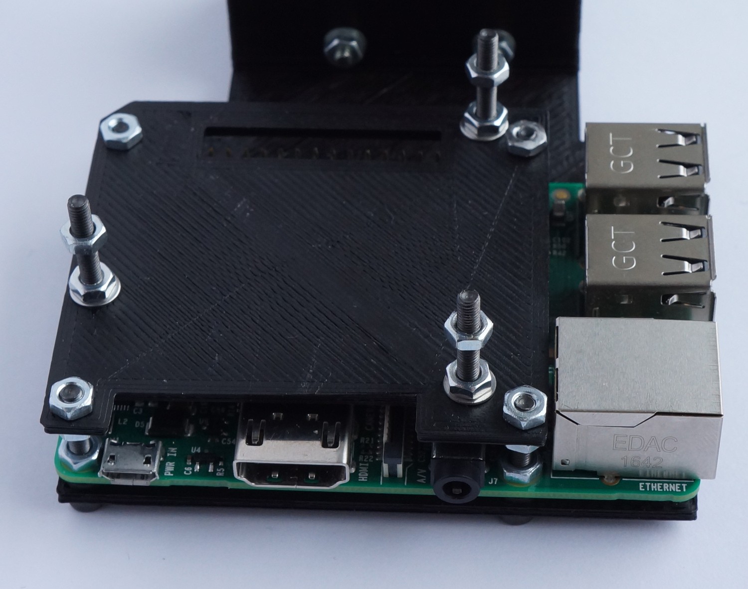
      The install screws in the sandwhich-layer (still 20mm M3's):Place it over the rpi:
      Install the cable to connect GPIOs on the rpi (the purple wire is connected to GPIO22):Install the nucleo:

      Finally, connect the nucleo and the CCD: [picture coming]

View all instructions

Enjoy this project?

Share

Discussions

David H Haffner Sr wrote 03/23/2018 at 11:43 point

Ha, this is certainly an interesting use of the TCD104 :)

  Are you sure? yes | no

esben rossel wrote 03/23/2018 at 12:50 point

thanks dave. It springs from a very specific need at my school. Each fall our students do (largish) projects, and glow sticks is a popular topic.
   Normally we'd send our kids to different university teaching labs to do their experiments, but this year the glow stick lab was full before my student even got around to apply for participation.
   Our normal spectrometers actually can be used for intensity measurements, but the sensitivity is not stellar, and the frame-rate is /low/ (1Hz or less depending on the vintage of the spectrometer).
   So we improvised a setup similar (at least conceptually) to the one presented here, but in a shoebox. It was not very user-friendly and/or safe to say the least, so I decided to put it in a nicer box and automate the data collection.

  Are you sure? yes | no

David H Haffner Sr wrote 03/23/2018 at 14:23 point

Very cool, a great experiment for plotting concentration is preparing 8 samples with different Mol concentration levels and 1 with a known concentration level and plotting the degradation of the S1 and S2 transition states every 30min and see how long it takes the oxidizing reaction to start falling off.

  Are you sure? yes | no

Similar Projects

Does this project spark your interest?

Become a member to follow this project and never miss any updates