 danjovic
-
1Step 1
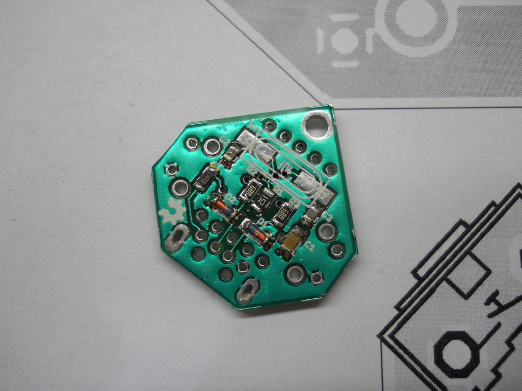
Start by assembling the components on the bottom side of the board:
- Resistors, R1, R2, R3, R4
- Capacitors, C1, C2, C3
- Diodes D1, D2
![]()
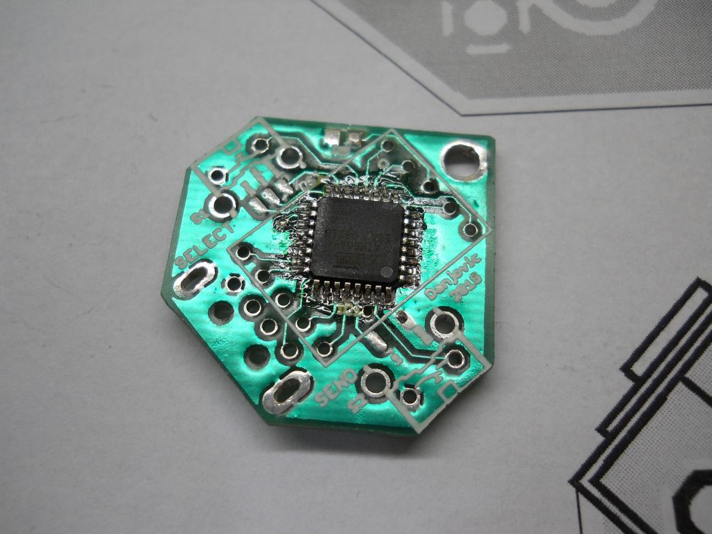
Then solder the microcontroller on the top side of the board
![]()
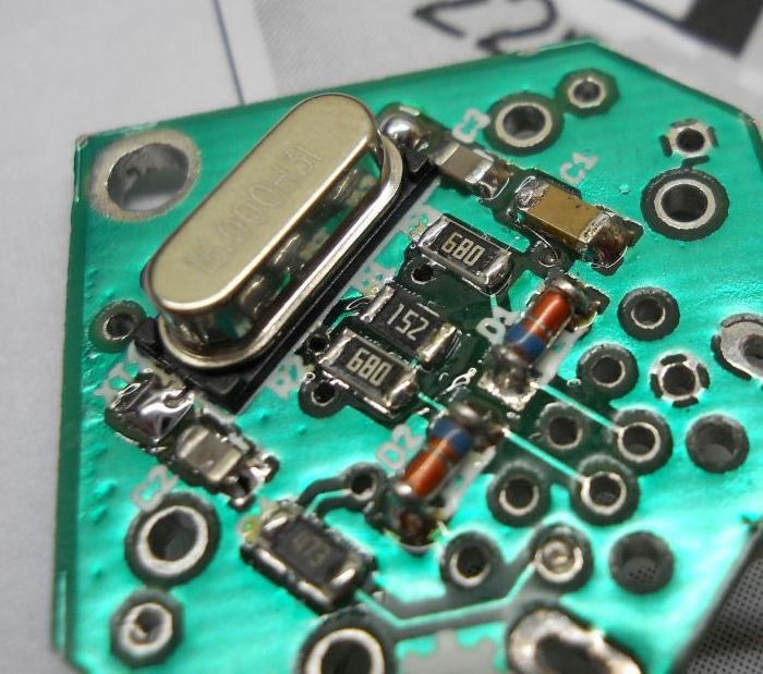
Now solder the Crystal.![]()
-
2Step 2
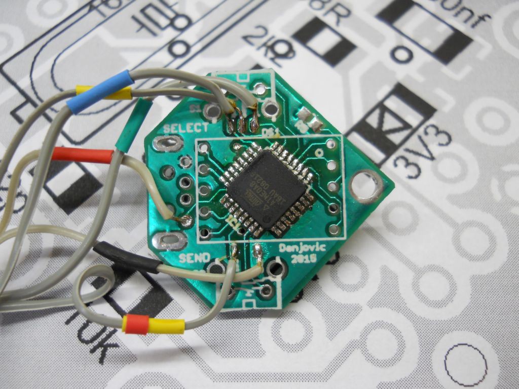
Solder some wires at the ISP connections of the board. The +Vcc will come from respective Pad in USB connector
![]()
Then connect the ISP to an AVR programmer. This procedure assumes the programmer is compatible with USBAsp, but other programmers can be used.
Plug the device into an USB port (or USB power supply) and check if the AVR can be programmed. It might be necessary to use 'slow speed' option of the programmer.
>avrdude -c usbasp -p m8
Now change to the booloader directory and type
make program
Now program the fusesmake fuse
Alternatively program the fuses by typing
avrdude -c usbasp -p m8 -U hfuse:w:0xc0:m -U lfuse:w:0x9f:m
-
3Step 3
make program
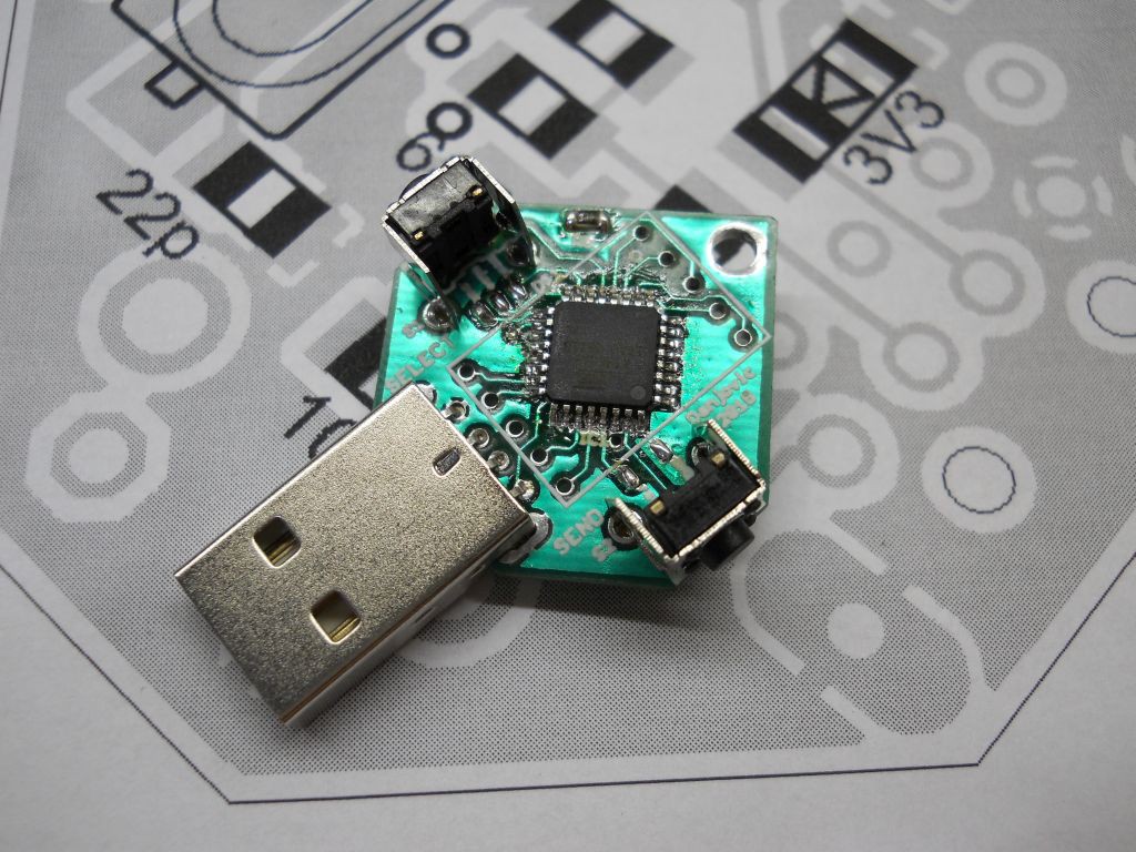
Now remove the ISP wires and solder the USB connector and the two buttons and the resistor R5.
![]()
-
4Step 4
Now insert the device with both buttons press and wait for USBASP device detection.
As soon as the device is programmed change to the passgen directory and type
make program
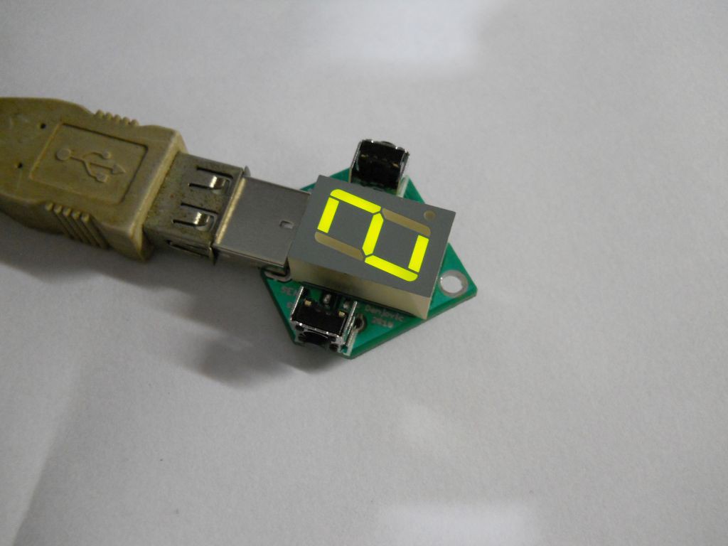
As soon as the programming finishes the device shall be detected as a keyboard device named 'passgen'
![]()
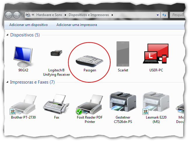
If everything is ok, unplug the device and then, finally assemble the 7 segment display.
![]()
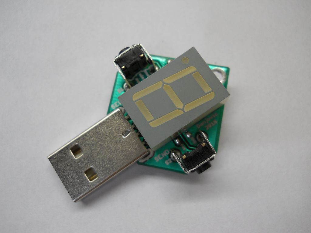
Reinsert the device and check with the SELECT button (or with NUM_LOCK key) that the slots can be advanced.
![]()
Discussions
Become a Hackaday.io Member
Create an account to leave a comment. Already have an account? Log In.