deʃhipu
-
Connections and Software
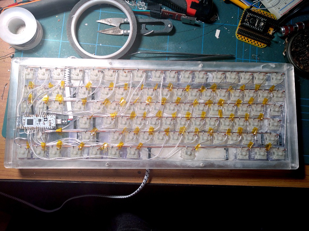
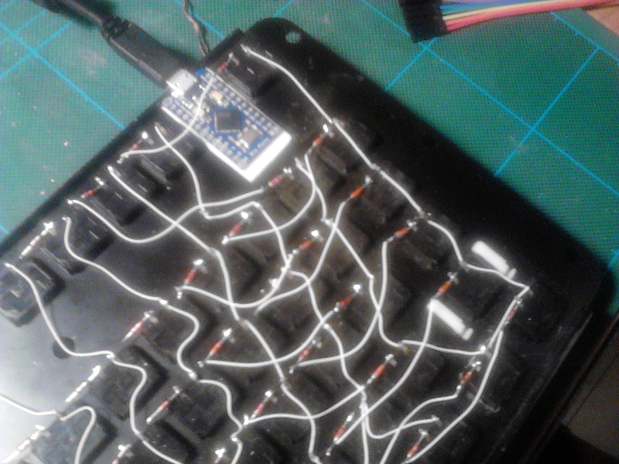
12/22/2015 at 21:58 • 0 commentsSo today I finished the second version of Alpen Clack -- this one built from scratch. As always, the most work-intensive part was soldering everything together. This time I used non-insulated wire, and added some kapton tape where it might touch anything -- this was much faster than removing the insulation from wires for soldering. The finished connections, before closing the keyboard:
![]()
Next comes the programming. I used the same firmware as for version one, except this time I had 6 columns and 17 rows (I kept the layout rotated 90°, as this is much easier to fit in 80 columns of source code). I also drilled a small hole for the reset button, to be able to press it with a pin.
Defining the layout was much easier this time, because of the saner matrix -- the Pololu A* Mini has enough pins broken out for me to not care so much about saving them. Still, I miscalculated a little bit and had to use one of the LED pins. That still left me two LEDs for CapsLock and ScrollLock (no NumLock), so it's fine.
Once everything was ready, I spent the customary 4 hours tearing my hair off and staring at the code, trying to debug a problem with it. In the end, it turned out that the compiler was caching a little more than it should, and recompiling everything from scratch solved it.
-
Electronics
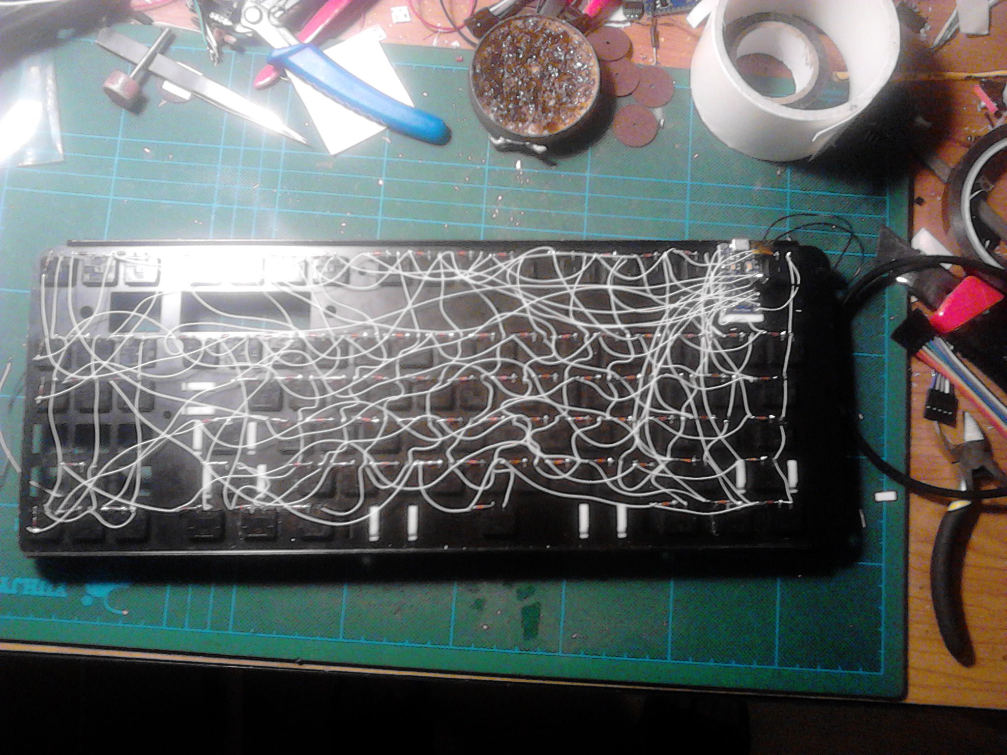
12/19/2015 at 17:11 • 0 commentsI fixed the switches in place with a little bit of glue (they can still be removed if needed), and I soldered the horizontal connections with a thick copper wire. Then I drilled the mounting holes for the A* board, and secured it in place with screws. I also drilled the hole for the USB cable, cut the plug from it, passed it through the hole and re-soldered a "naked" plug back. The board is mounted above the arrow keys in such a way, that you can see the LEDs on it -- I will use those for CapsLock and so on. Finally, I taped the metal back-plate with some transparent tape, so that there are no shorts, and screwed it to the back -- to make sure everything fits properly. The keyboard got much sturdier now, and I think it won't need additional enforcing.
![]()
Next step is soldering the SMD diodes and the vertical columns, then connecting it all to the board, and modifying the firmware for this particular layout. It's almost finished.
-
Switches and Keycaps
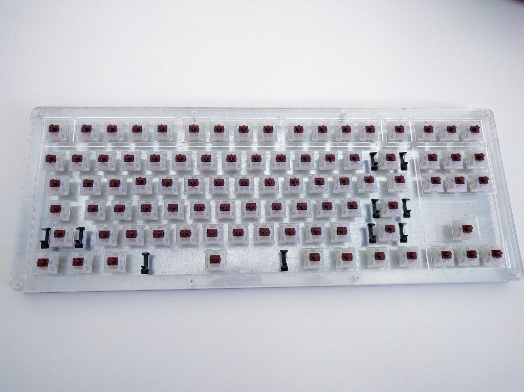
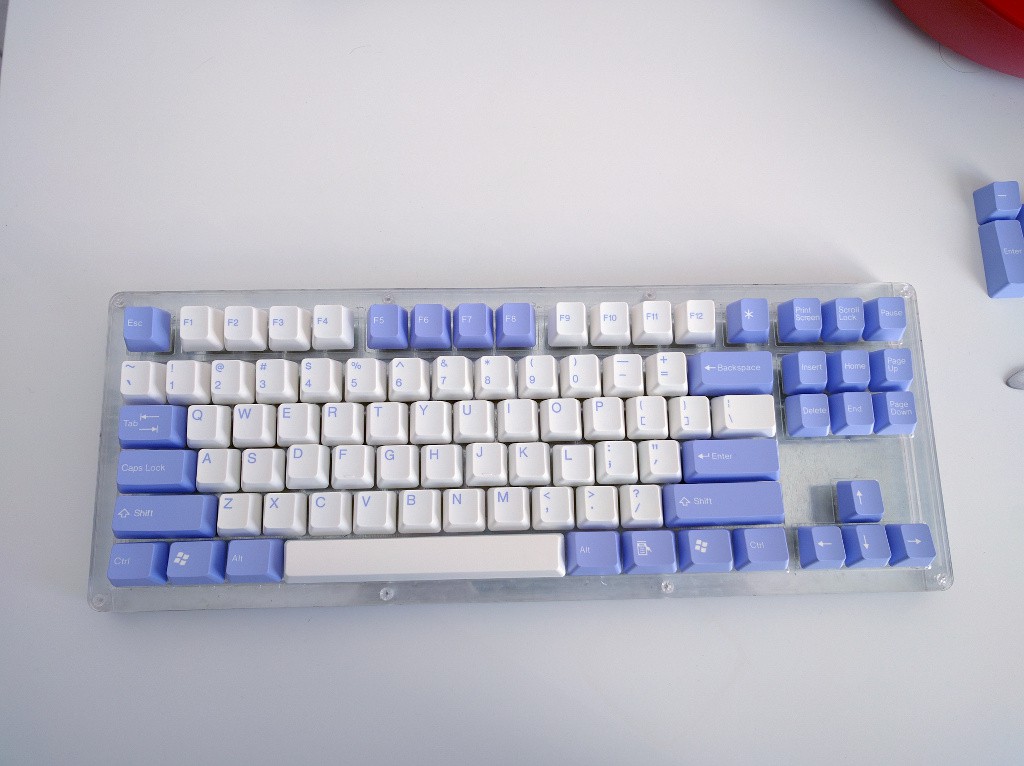
12/17/2015 at 10:59 • 0 commentsThe Gateron switches and the keycaps that I ordered on Massdrop finally arrived. The switches fit nicely:
![]()
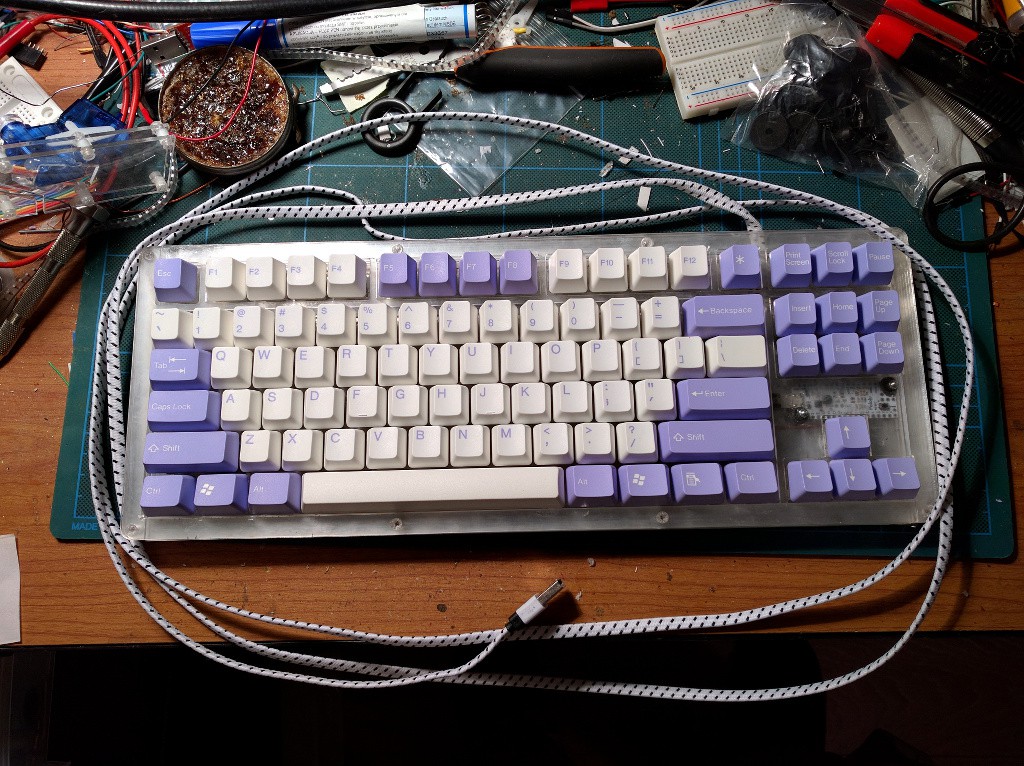
And the with the keycaps:
![]()
I still have two problems to solve, though. First, while the switches fit, they are not particularry well kept in place by their snaps, which apparently are designed for a thinner board. I will need to hold them in place with something. Second, the acrylic sheet on which they sit is really flimsy. I will either need to find something more robust, or have them touch the back plate for stability. We will see how it develops.
-
Metal Back
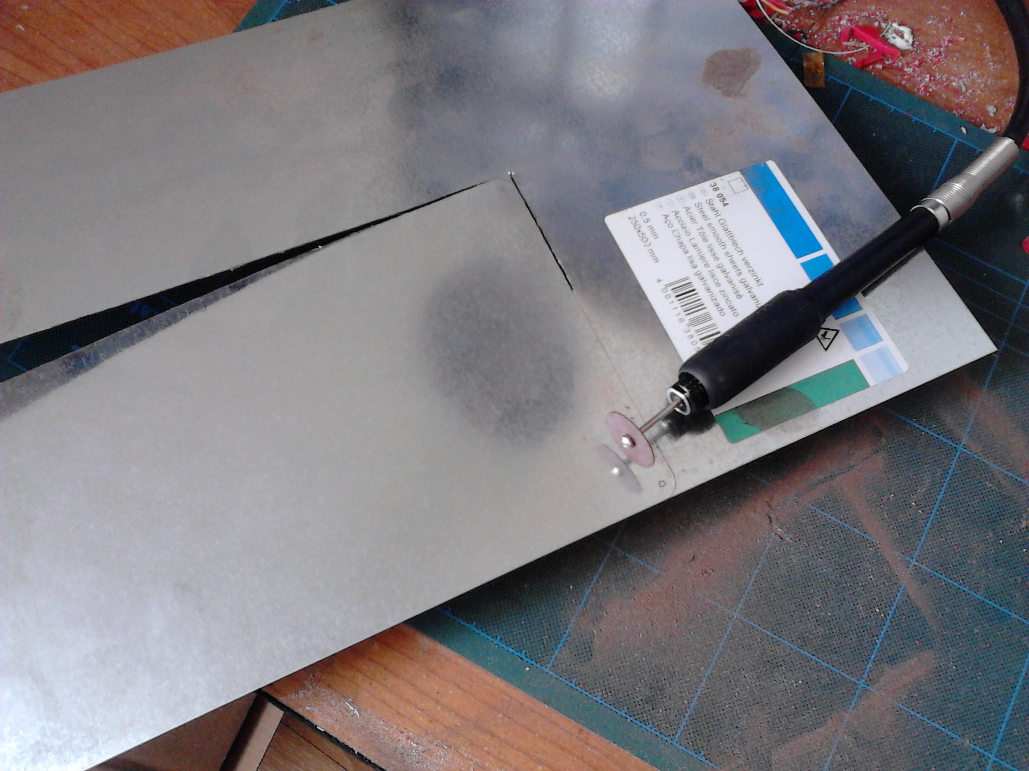
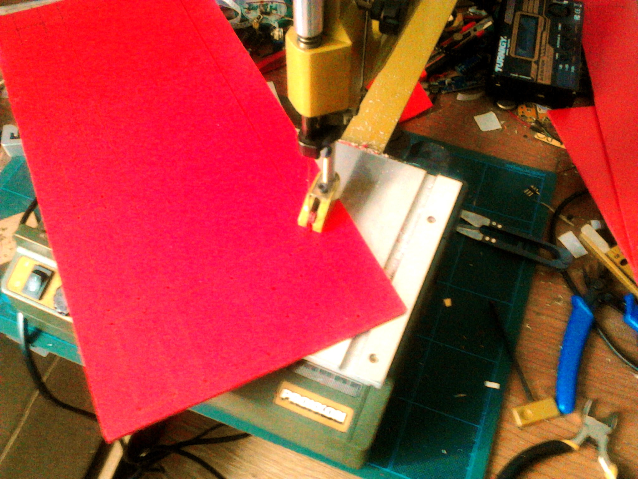
11/10/2015 at 20:11 • 0 commentsWhile the switches and keycaps will take their time to arrive, I'm still working on the case. I have cut a back out of stainless steel that I have found at the local hobby supplies store. Took 3 stone wheel for my dremel clone, but it looks good enough.
![]()
-
Laser Cutting
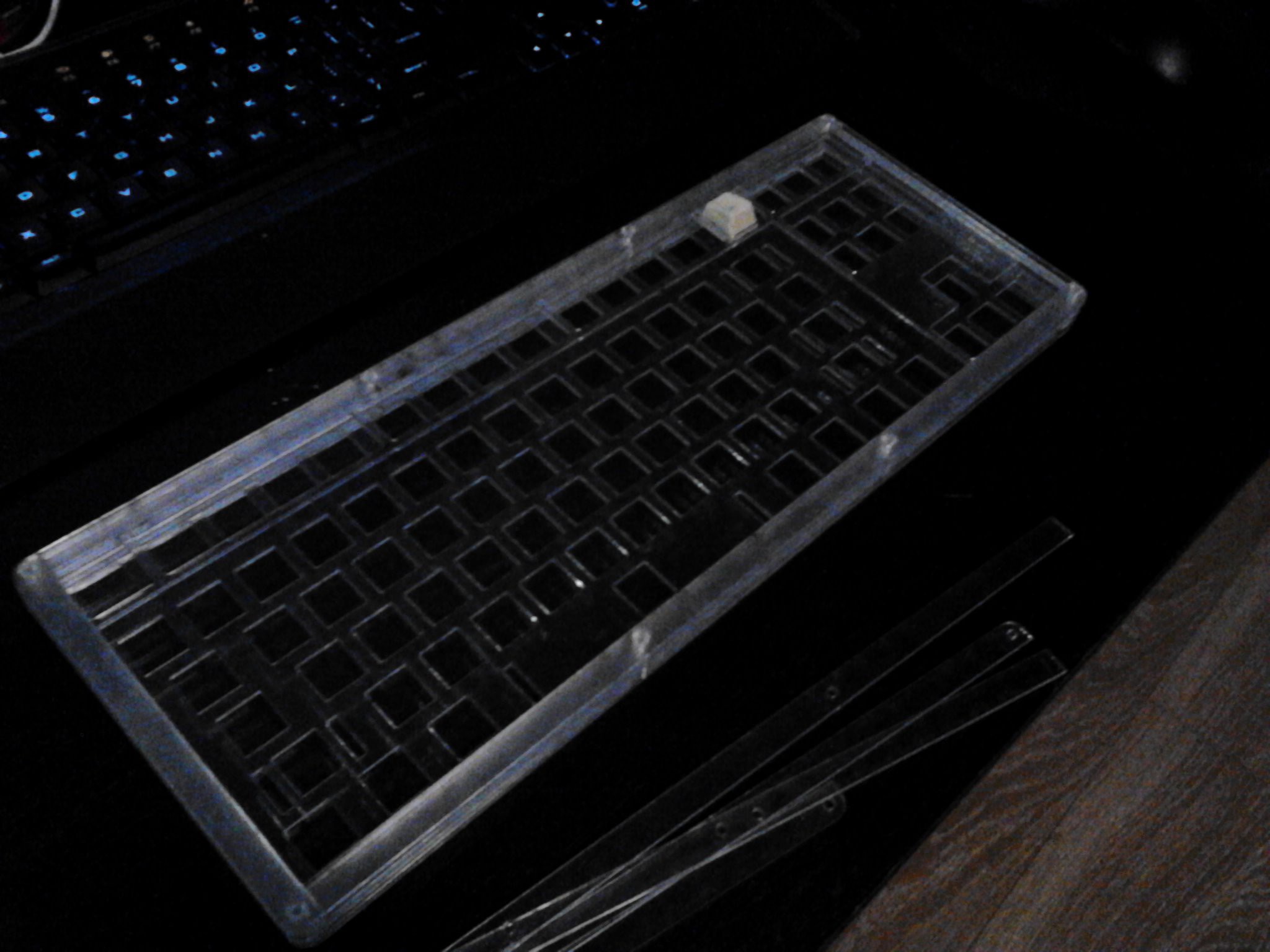
11/05/2015 at 20:01 • 0 commentsThis is my second attempt at laser cutting, and it went much smoother this time, in a large part due to help from the people at FabLab. I generated the switch plate, and then used that as a base for the face plate, back and the layers for the sides. I made a mistake that I didn't make the holes in the back plate a little bit smaller -- so that I could tap them and screw in the bolts into them directly, but I think that I can fix it with some glue and a drill.
![]()
Since the keyboard is transparent, I will need to be much more careful about soldering and generally cable routing, to make it look good. I ordered a white A-Star module for the controller, mostly because it has all the 26 pins broken out, but also because it's white and will look cool. I'm going to make it visible right over the arrow keys, and to use the LEDs on it for the CapsLock and other indicators.
I also ordered some brown Gateron switches (they should look nice too, as they have transparent cases), and some keycaps (they didn't have transparent ones), they should arrive in a couple of weeks and then I can continue this project.
-
Resources for Keyboard Makers
11/03/2015 at 13:21 • 0 commentsSo, I guess I caught the bug, and I will be making another keyboard, this time completely from scratch. This time I'm going to carefully pick the switches, design the layout, have the case laser-cut, etc. And that means, I will need these tools:
-
Use a Pro Micro in a Keyboard
11/02/2015 at 22:07 • 11 commentsSo you want to build your own keyboard (or keyboard-like device), but you are not sure what to use for the brains and how to connect and program it? I will describe what I came up with for the #Alpen Clack keyboard.
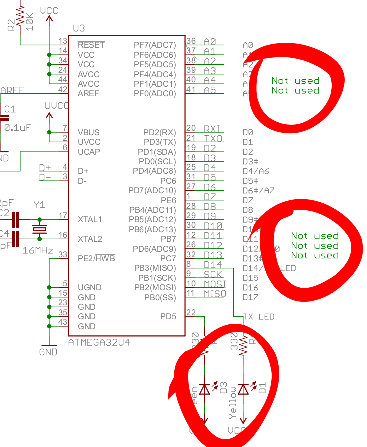
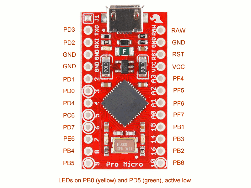
The ATmega32u4 microcontroller is an excellent choice for any HID device, such a mouse, a joystick or a keyboard. That's mostly because it has hardware USB support, so you don't have to muck about with unreliable and hacky bit-banged VUSB. There are three popular boards with that microcontroller: Arduino Leonardo, Teensy 2.0, and Pro Micro (not to be confused with Pro Mini, which uses ATmega328). Arduino Leonardo is too big for our needs. Teensy 2.0 is quite expensive. Pro Micro can be had for about $4 in singles from the usual oriental sources. Sounds like a winner. Let's look at the pinout:
![]()
According to this diagram, we have 18 usable pins. An 18-key keyboard is not very useful. Can we somehow connect more keys? Turns out we can, by using a key matrix. We basically make rows and columns, and put switches on the crossings. Then we scan that repeatedly to figure out which ones are pressed. We add diodes, so that the pressed keys won't interfere with each other. Simple.
So, with 18 pins, the largest matrix we can get is a square 9×9. That's 81 keys. Hmm, that may be fine for those tiny, chocolate bar keyboards, but a modern PC keyboard has 105 keys. Even if we ditch the keypad, like I did in my keyboard, that only removes 17 keys. We are still 7 keys short!
Wait, what does it say about LEDs at the bottom there? Two more independent pins? Great, we only have to remove the two resistors and solder wires in their place, and we have 20 pins for our disposal. That gives us the largest matrix of 10×10, so 100 keys. Still not enough for the full layout, but should be fine for a tenkeyless keyboard.
Next, programming the thing. After a short search, I found the TMK Keyboard firmware, which is just perfect for our needs. All we need to do is to copy the "onekey" example keyboard, and modify the config.h, keymap.c and matrix.c files to fit our keyboard.
In config.h, we have to set the correct number of rows and columns. I used 8 columns and 11 rows in my keyboard, which gave me the 88 keys I needed (actually 87). You can also change some other options here and in the Makefile.
Next, the hard part -- matrix.c. You will need to define four functions: init_cols, read_cols, unselect_rows and select_row. You can look at all the examples included in the repository to get an idea what they need to do. Basically, init_cols sets all the column pins in INPUT mode with internal pull-up resistors. It's called once at the start. Next, the read_cols function reads the state of all those column pins, and reports it as a single byte (or more, if you have more than 8 columns, but see below). The unselect_rows function sets all the row pins to floating, and finally the select_row function sets the specified row pin to low. That's it.
One note about having more than 8 columns: while the code looks like it should support it, I didn't manage to get that to work. I'm not too worried, because I only needed 8 in the end, but if you need more, you will probably need to copy the matrix_scan function from one of the larger examples to get it to work.
Lastly, you need to define the key map -- basically to tell the firmware which key is which. You do that in keymap.c, by defining an array of arrays of arrays... I mean, an array of layers, each layer being an array of rows, each row being an array of columns, each column being an array of keys. The layers let you setup cool effects with special keys and such, see the keymap documentation for details.
Lastly, we need to modify the Makefile for our board. I used Makefile.pjrc, because the default one doesn't support N-key rollover yet. Set the following variables:
MCU = atmega32u4
OPT_DEFS += -DBOOTLOADER_SIZE=512
PROGRAM_CMD = avrdude -p $(MCU) -P /dev/ttyACM0 -c avr109 -U flash:w:$(TARGET).hex
Now you are ready to program your board. Connect a switch between the GND and RST pins, connect the board to USB and press the switch two times quickly. That puts the board into programming mode. Now run "make -f Makefile.pjrc program", and it should compile and burn the firmware to your board. After that it will be visible in "lsusb" command as whatever ID you set in the config.h file, and shorting any row pin with any column pin should produce key presses. Now you can solder the board into your matrix, and you are done. -
Case
11/02/2015 at 21:14 • 0 commentsWhile naked keyboard does have its appeal, it's time to build a case for this baby. I started by cutting out the holes for the keys in the face plate of depron:
![]()
They are not perfect -- laser cutter would do them better -- but beggars can't be choosers. Next, I glued strips of depron around the edges, placed my keyboard on them, and glued some more layers of strips of depron. Finally, a large white sheet glued lightly at the bottom:
![]()
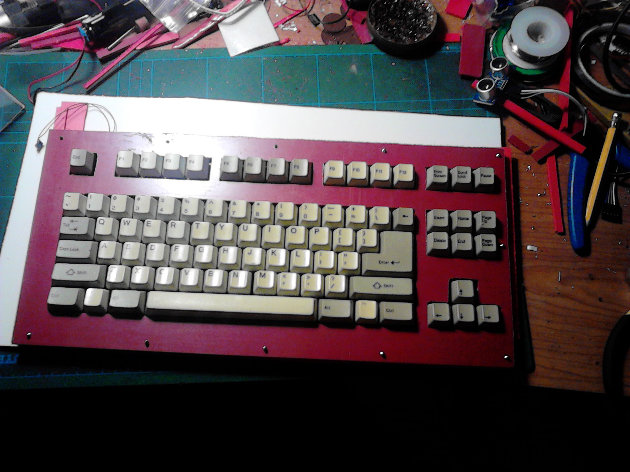
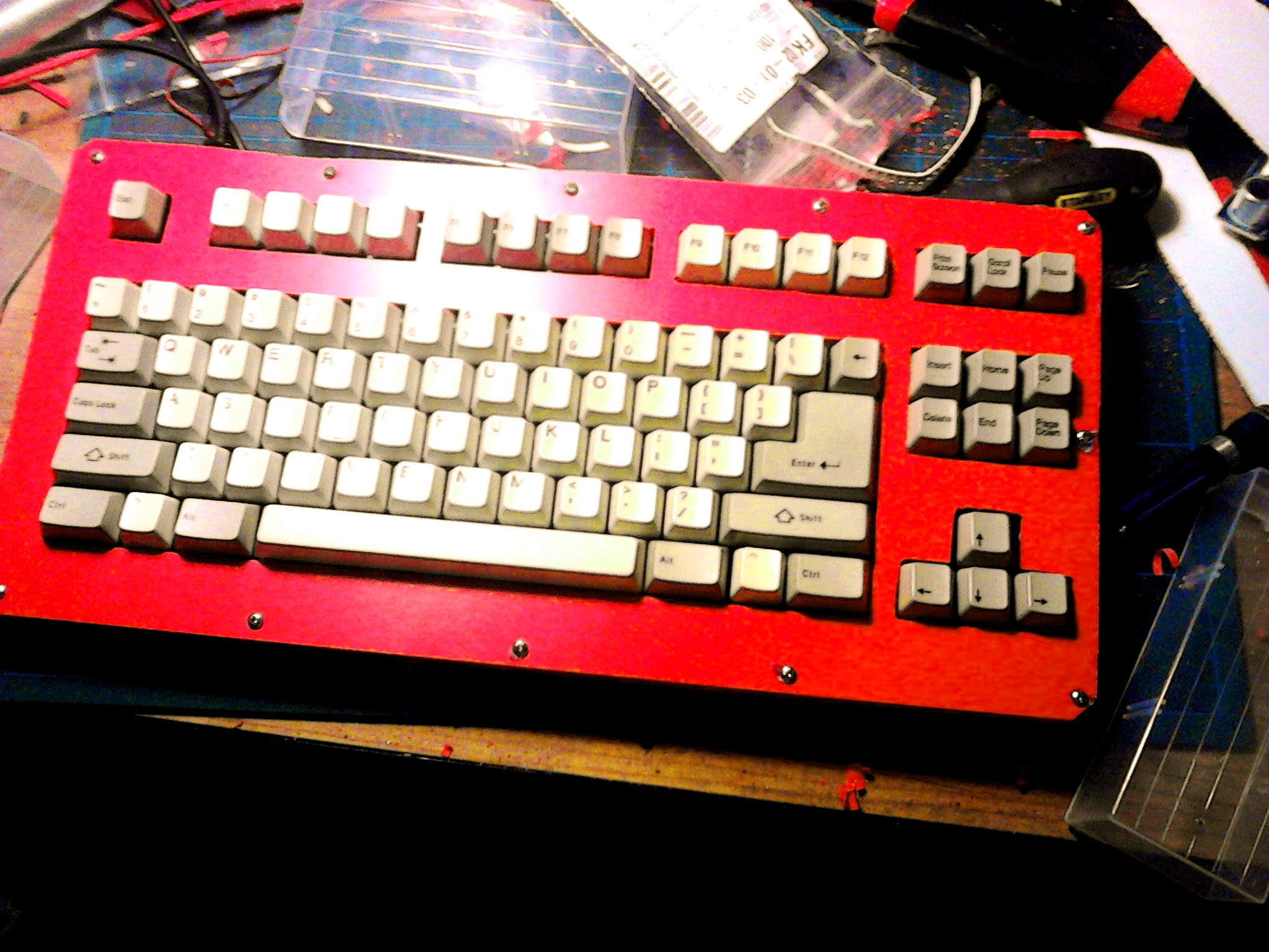
(The keyboard is pink because of the protective foil on it.) Some screws help to keep it all together. Next, I cut around the edges with scroll saw, to get all those layers to exactly same shape. Then I replaced the screws, cut their ends, added rubber feet and voila:
![]()
After some testing, I decided that I will have to lower the front edge a little -- by cutting the whole keyboard into a wedge shape. But that's for tomorrow, as I won't be using power tools at night, waking up the neighbours.
-
Matrix 2
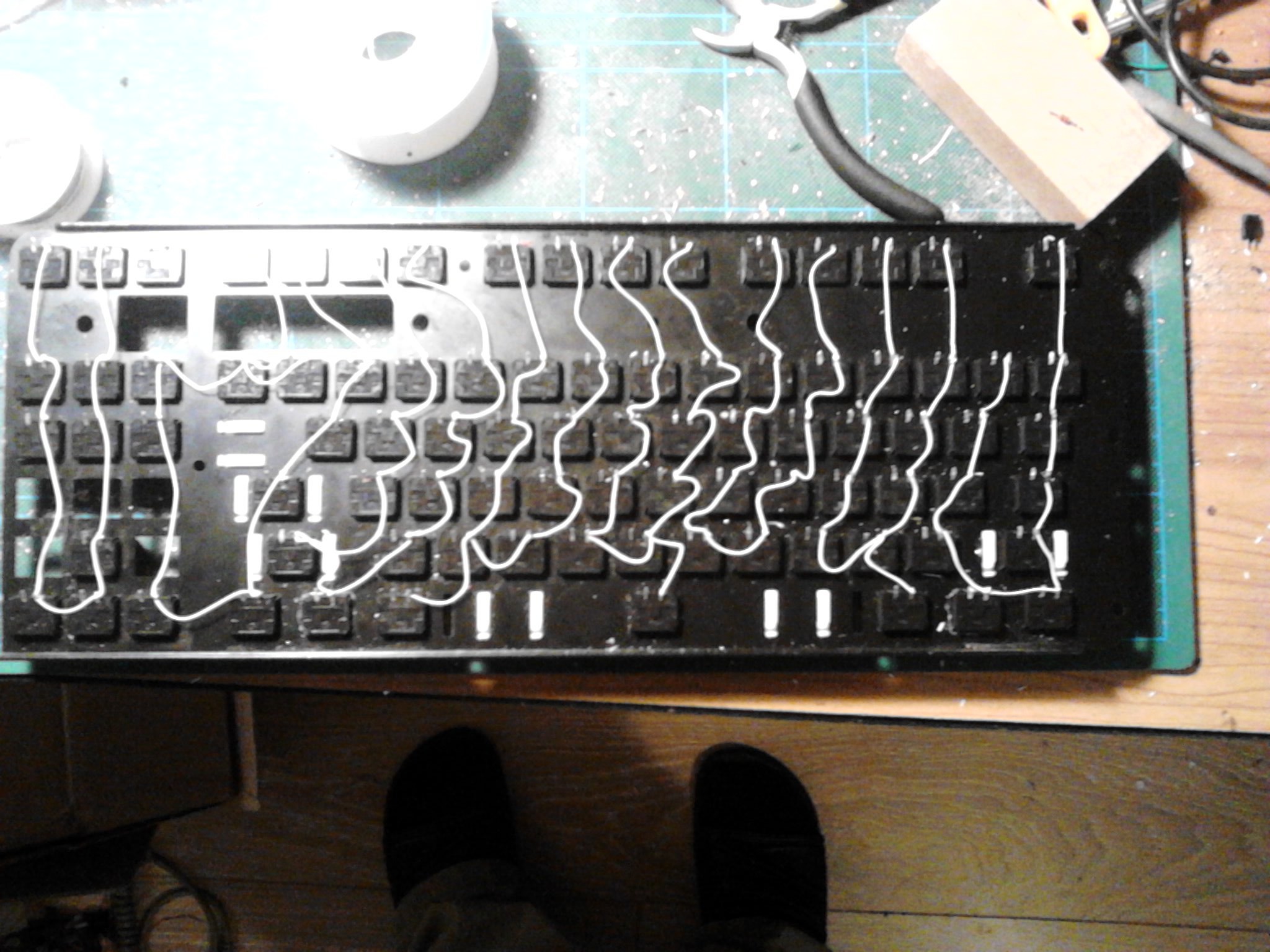
11/01/2015 at 18:59 • 0 commentsThis was the most laborious step of the work. I had to solder all the keys, defined the pins for the rows and columns, and defined the key map. I started with soldering the columns:
![]()
Since I need the matrix to be as close to rectangle, as possible, to save pins, I merged pairs of columns. This way I have 8 columns with 11 rows each (except for one, that only has 10 rows).
Next, I made a hole in the plate for the USB socket, and attached the microcontroller board with two-sided tape:
You can also see the beginnings of rows with the diodes. Then came all the remaining connections:![]()
![]() Now, time for the firmware.
Now, time for the firmware.I copied the "onekey" example from the tmk_keyboard repository, and changed the names in the makefile and settings in config.h:
/* key matrix size */
#define MATRIX_ROWS 11
#define MATRIX_COLS 8

/* define if matrix has ghost */
//#define MATRIX_HAS_GHOST

/* Set 0 if debouncing isn't needed */
#define DEBOUNCE    5

/* key combination for command */
#define IS_COMMAND() ( \
    keyboard_report->mods == (MOD_BIT(KC_LSHIFT) | MOD_BIT(KC_RSHIFT)) \
)

/*
 * Feature disable options
 *  These options are also useful to firmware size reduction.
 */

/* disable debug print */
#define NO_DEBUG

/* disable print */
#define NO_PRINT

/* disable action features */
//#define NO_ACTION_LAYER
//#define NO_ACTION_TAPPING
#define NO_ACTION_ONESHOT
#define NO_ACTION_MACRO
#define NO_ACTION_FUNCTION
Then I modified the matrix.c file to support a little larger keyboard:
/* Column pin configuration
 * col: 8
 * pin: F4 F5 F6 F7 B1 B3 B2 B6
 */
static void  init_cols(void) {
    // Input with pull-up(DDR:0, PORT:1)
    DDRB  &= ~0b01001110;
    PORTB |=  0b01001110;

    DDRF  &= ~0b11110000;
    PORTF |=  0b11110000;
}

static matrix_row_t read_cols(void) {
    return (PINF&(1<<4) ? 0:(1<<0)) |
           (PINF&(1<<5) ? 0:(1<<1)) |
           (PINF&(1<<6) ? 0:(1<<2)) |
           (PINF&(1<<7) ? 0:(1<<3)) |
           (PINB&(1<<1) ? 0:(1<<4)) |
           (PINB&(1<<3) ? 0:(1<<5)) |
           (PINB&(1<<2) ? 0:(1<<6)) |
           (PINB&(1<<6) ? 0:(1<<7));
}

/* Row pin configuration
 * row: 11
 * pin: D3 D2 D1 D0 D4 C6 D7 E6 B4 B5 B0
 */
static void unselect_rows(void) {
    // Hi-Z(DDR:0, PORT:0) to unselect
    DDRD  &= ~0b10011111;
    PORTD &= ~0b10011111;

    DDRC  &= ~0b01000000;
    PORTC &= ~0b01000000;

    DDRE  &= ~0b01000000;
    PORTE &= ~0b01000000;

    DDRB  &= ~0b00110001;
    PORTB &= ~0b00110001;
}

static void select_row(uint8_t row) {
    // Output low(DDR:1, PORT:0) to select
    switch (row) {
        case 0:
            DDRD  |= (1<<3);
            PORTD &= ~(1<<3);
            break;
        case 1:
            DDRD  |= (1<<2);
            PORTD &= ~(1<<2);
            break;
        case 2:
            DDRD  |= (1<<1);
            PORTD &= ~(1<<1);
            break;
        case 3:
            DDRD  |= (1<<0);
            PORTD &= ~(1<<0);
            break;
        case 4:
            DDRD  |= (1<<4);
            PORTD &= ~(1<<4);
            break;
        case 5:
            DDRC  |= (1<<6);
            PORTC &= ~(1<<6);
            break;
        case 6:
            DDRD  |= (1<<7);
            PORTD &= ~(1<<7);
            break;
        case 7:
            DDRE  |= (1<<6);
            PORTE &= ~(1<<6);
            break;
        case 8:
            DDRB  |= (1<<4);
            PORTB &= ~(1<<4);
            break;
        case 9:
            DDRB  |= (1<<5);
            PORTB &= ~(1<<5);
            break;
        case 10:
            DDRB  |= (1<<0);
            PORTB &= ~(1<<0);
            break;
    }
}
Finally, with some mistakes and experimenting, I defined the key map in keymap.c:static const uint8_t PROGMEM keymaps[][MATRIX_ROWS][MATRIX_COLS] = { { {KC_PGUP, KC_PSCR, KC_F10, KC_F8, KC_SPC, KC_NO, KC_F2, KC_1 }, {KC_PGDN, KC_F12, KC_MINS, KC_9, KC_F6, KC_F4, KC_3, KC_Q }, {KC_HOME, KC_BSPC, KC_LBRC, KC_O, KC_7, KC_5, KC_E, KC_A }, {KC_RGHT, KC_SLCK, KC_QUOT, KC_L, KC_U, KC_T, KC_D, KC_Z }, {KC_DEL, KC_NO, KC_RSFT, KC_DOT, KC_J, KC_G, KC_C, KC_LGUI}, {KC_END, KC_BSLS, KC_RGUI, KC_RALT, KC_M, KC_B, KC_LALT, KC_LCTL}, {KC_UP, KC_RCTL, KC_SLSH, KC_COMM, KC_N, KC_V, KC_X, KC_LSFT}, {KC_DOWN, KC_ENT, KC_SCLN, KC_K, KC_H, KC_F, KC_S, KC_CAPS}, {KC_LEFT, KC_RBRC, KC_P, KC_I, KC_Y, KC_R, KC_W, KC_TAB }, {KC_BRK, KC_EQL, KC_0, KC_8, KC_6, KC_4, KC_2, KC_GRV }, {KC_INS, KC_F11, KC_F9, KC_F7, KC_F5, KC_F3, KC_F1, KC_ESC }, }, };Nothing fancy for now, just regular keyboard. Since the columns are doubled, the layout definition doesn't look very readable, but it works.Next, I will experiment with some action keys and add secondary functions to some of the keys, so that I have media keys and whatnot.
Also, I still need to make the case for this keyboard. I will get some cardboard tomorrow and start prototyping.
-
Matrix
10/31/2015 at 18:02 • 0 commentsThe favorite microcontroller for all things USB, such as keyboards, joysticks or mice, is the good old ATMega 32U4, well known from the Arduino Leonardo. Of course I don't plan to stuff an Arduino-footprint board inside my keyboard, I need a smaller board. There are two popular small boards with that chip. One is the Pro Micro, the other is Teensy 2.0. I have some Pro Micros, which I purchased for around $4, in my drawer just for the occasions like that. The keyboard modding community seems to prefer the Teensy for some reason, even though it's around $15. Oh well, I suspected it was because it had a GUI uploader.
I was wrong.
It turns out that Pro Micro doesn't break out all the pins. In fact, it only breaks out 18 GPIO pins, and uses 2 more for build-in LEDs, leaving the remaining 5 pins unconnected. Just take a look at the schematic:
![]()
OK, with some delicate soldering I can reclaim the two LED pins -- just remove the LEDs and solder wires in that place. That gives me 20 pins to work with. My keyboard has 88 keys. That means, that if I make a matrix 8×11, I can support them all with 19 pins, and even have one pin left for a LED or something. Yay. But 8×11 is not exactly how the keyboard looks physically -- it's more like 5.5×16 (some columns have 5 rows, some have 6). So, to get 8×11, I will have to transpose it and merge every two neighboring columns together. That's doable, it just means I will have fun time converting the layouts.
Now, let's look for some ready-to-use firmware, so that I don't have to do all this coding myself (not that it's very complicated, but I'm lazy). For that chip, this seems to be pretty popular: https://github.com/tmk/tmk_keyboard
First, I burned one of the example keyboards to the board with avrdude:
avrdude -p atmega32u4 -P /dev/ttyACM0 -c avr109 -U flash:w:gh60.hex(you have to get it into the boot mode first by pressing reset right when it boots).
Then I connected some of the switches to some of the column/row pins, and pressed them -- and voila, it typed some letters! So the firmware works great.
Next, I will have to modify it to support my particular keyboard layout, with this almost square matrix. Looking at the matrix.c file in the examples, you can see code like:
/* Row pin configuration
 * row: 0   1   2   3   4
 * pin: D0  D1  D2  D3  D5
 */
static void unselect_rows(void)
{
    // Hi-Z(DDR:0, PORT:0) to unselect
    DDRD  &= ~0b00101111;
    PORTD &= ~0b00101111;
}
Hmmm.... Does that mean I need to have all row pins on the same port? I need 8 rows, so that would be doable... Let's see... Nope. Whoever designed the Pro Micro, he or she left out a single pin from each port, so that no port has a complete set of pins broken out. Splendid. Let's look at the other examples...
OK, I can pretty much write anything I want in those functions, all I need is to initialize the pins I want and read them all into a single number with something like:
static uint8_t read_rows(void)
{
    return (PIND&(1<<0) ? (1<<0) : 0) |
           (PIND&(1<<1) ? (1<<1) : 0) |
           (PIND&(1<<2) ? (1<<2) : 0) |
           (PIND&(1<<3) ? (1<<3) : 0) |
           (PIND&(1<<5) ? (1<<4) : 0) |
           (PINB&(1<<7) ? (1<<5) : 0);
}
Not very pretty, I bet I could write it nicer, but that should work.OK, writing it all and writing the layout definition is going to take some time, but at least I know how to proceed. See you at the other end.
 Now, time for the firmware.