 x3n0x
x3n0xBecause the Technology for 'Nerve Induction' has not yet been invented, and Raytheon's magical directed energy stuff is not available to mere mortals, We have elected to use a different approach: Low current High Voltage and some support equipment such as an Arduino, a Wave Shield, and some control and sense circuitry. The equipment will be mounted in a replica 'Pain Box' prop, and Sound clips from the movie will be used to give feedback or attract test subjects. The box will run a Pre-programmed 'Pain' profile, and rate the subject's performance as the test progresses. When the box is idle, it will look for people in the room to pass in front of it, and 'invite' them using 'The Voice' to participate in the test.
0%
0%
Become a Hackaday.io member
Already have an account? Log in.
Just one more thing
To make the experience fit your profile, pick a username and tell us what interests you.
Pick an awesome username
hackaday.io/
Your profile's URL: hackaday.io/username. Max 25 alphanumeric characters.
Pick a few interests
Projects that share your interests
People that share your interests
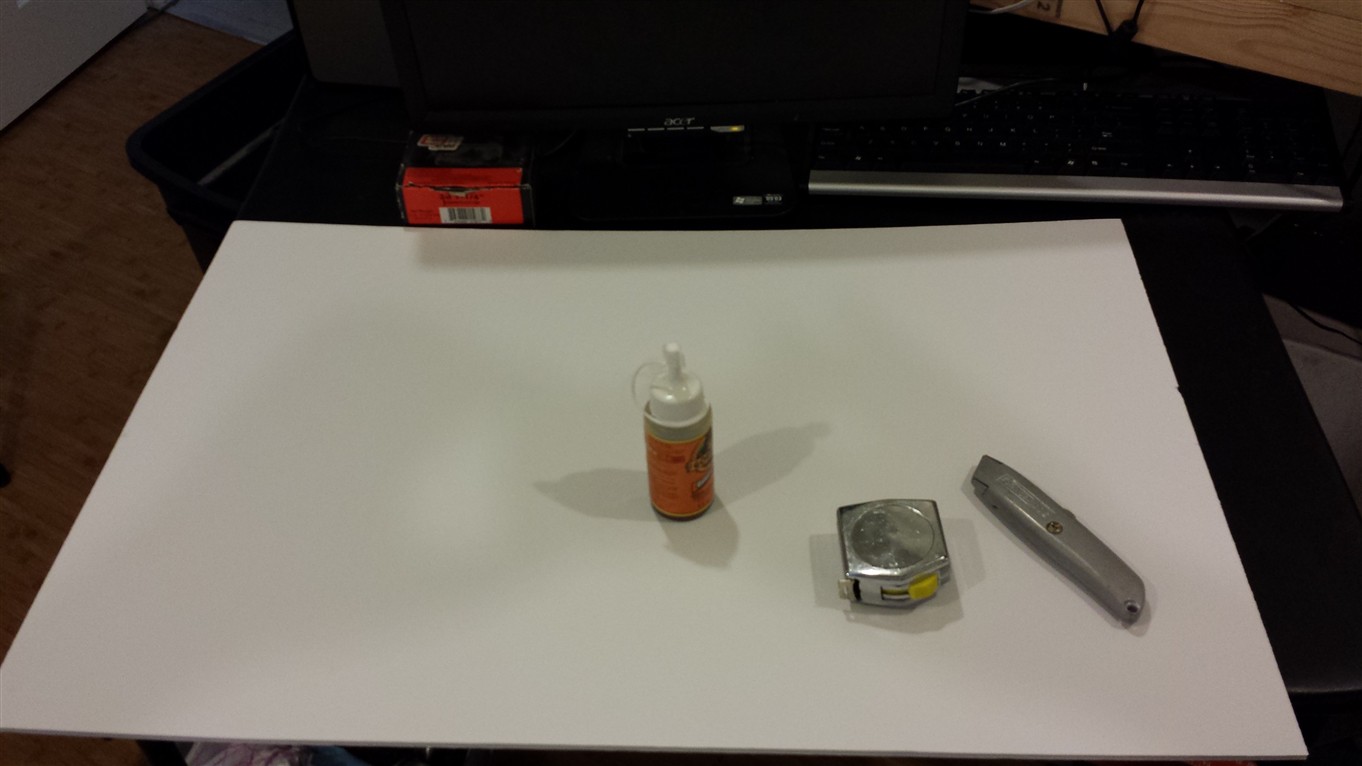
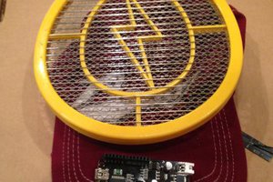
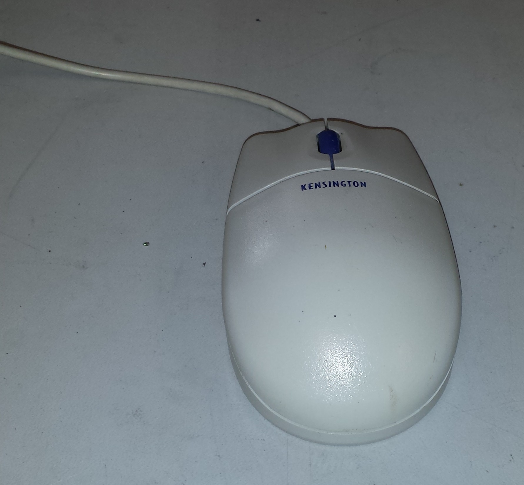 Here is our victim.
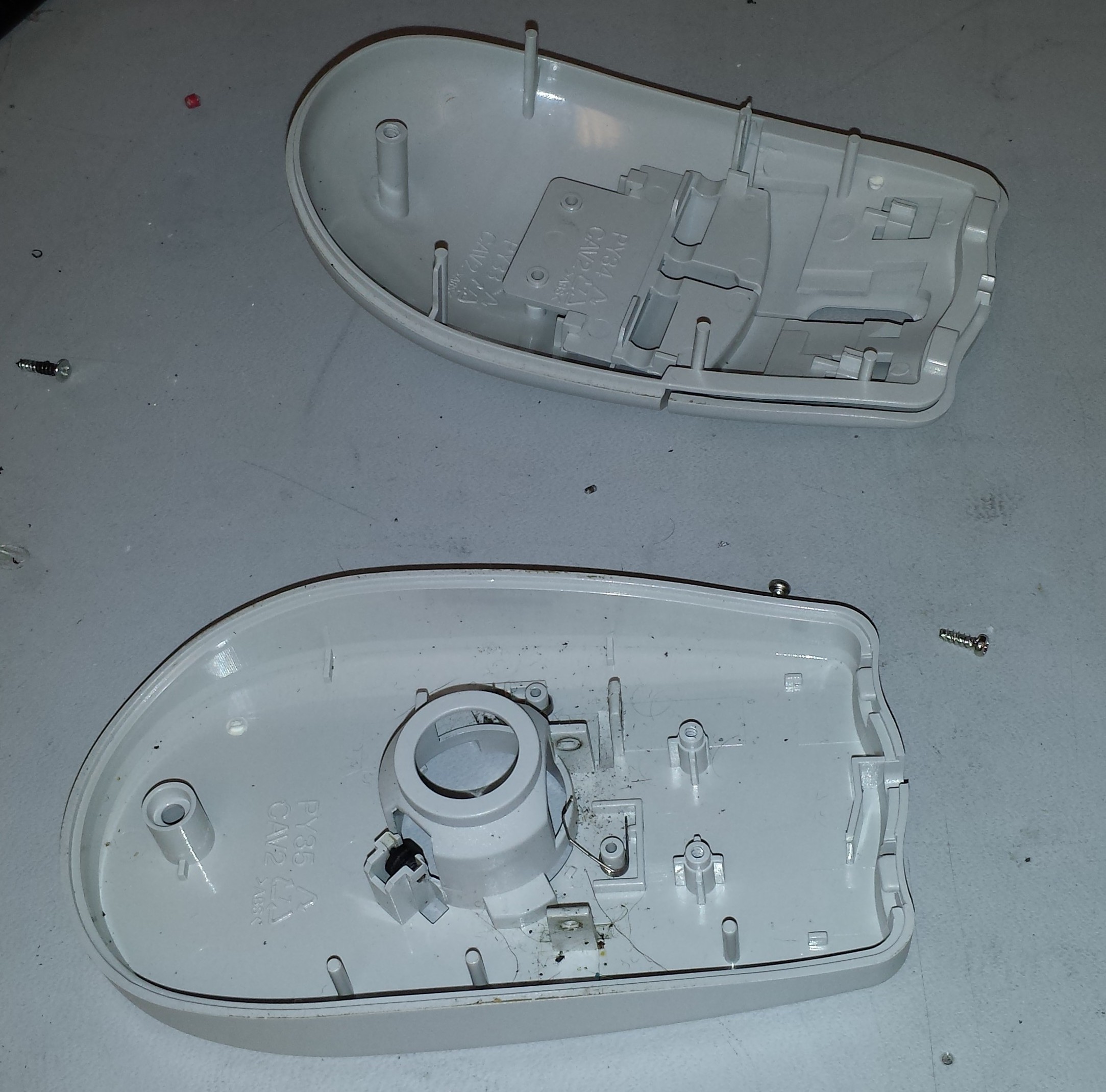 First thing on the agenda is open the thing up and pull out its guts. A single screw (seen in the photo above) is the only thing holding this thing together. I clipped off the cord and pulled the PCB and ball out leaving me with the above.
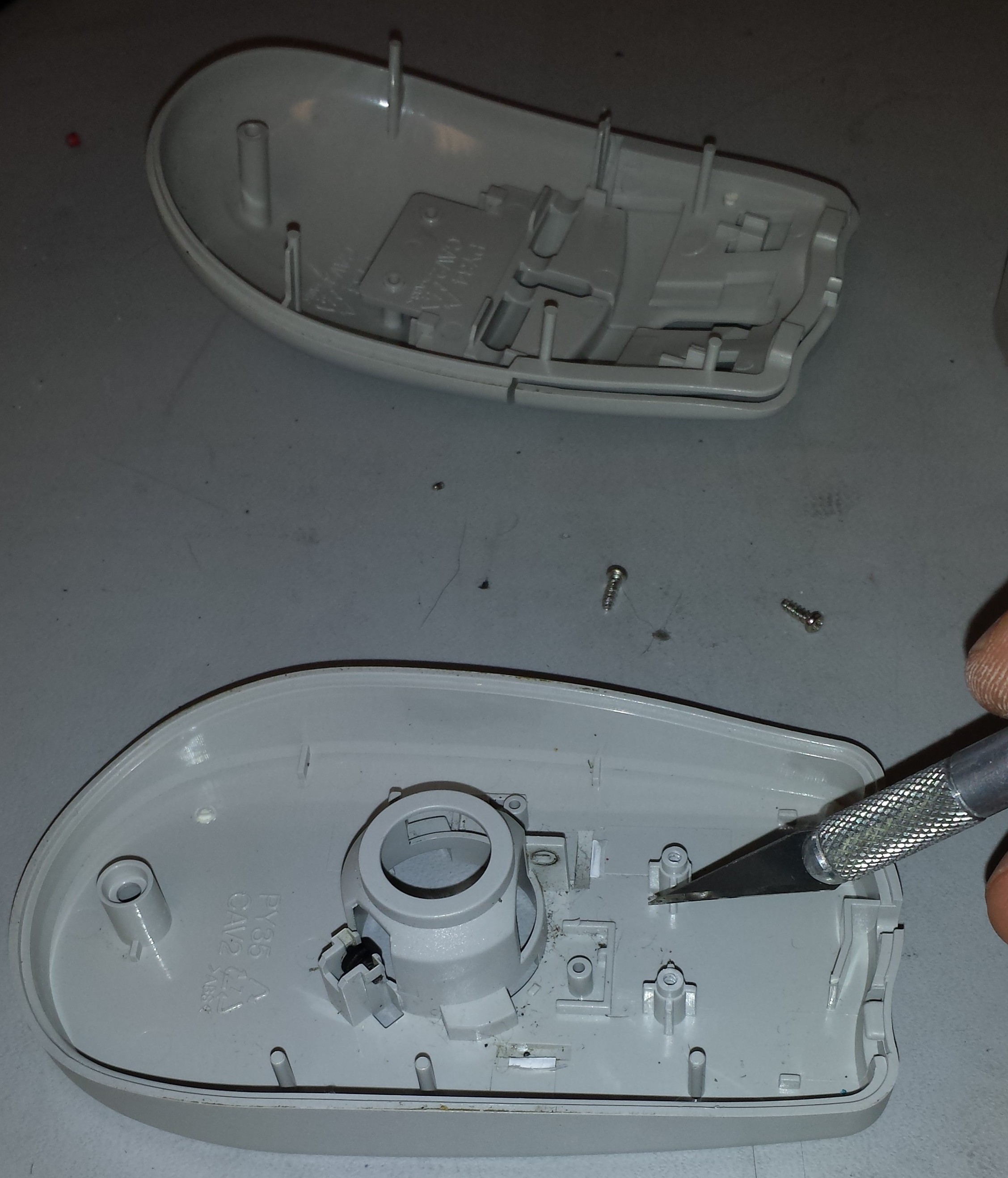 Next, I needed to clear out some of the plastic bosses and other features to make room for the Hell Mouse guts. My method was to score the bottom of the plastic feature I was trying to remove and snap it off using a pair of needle nose pliers.
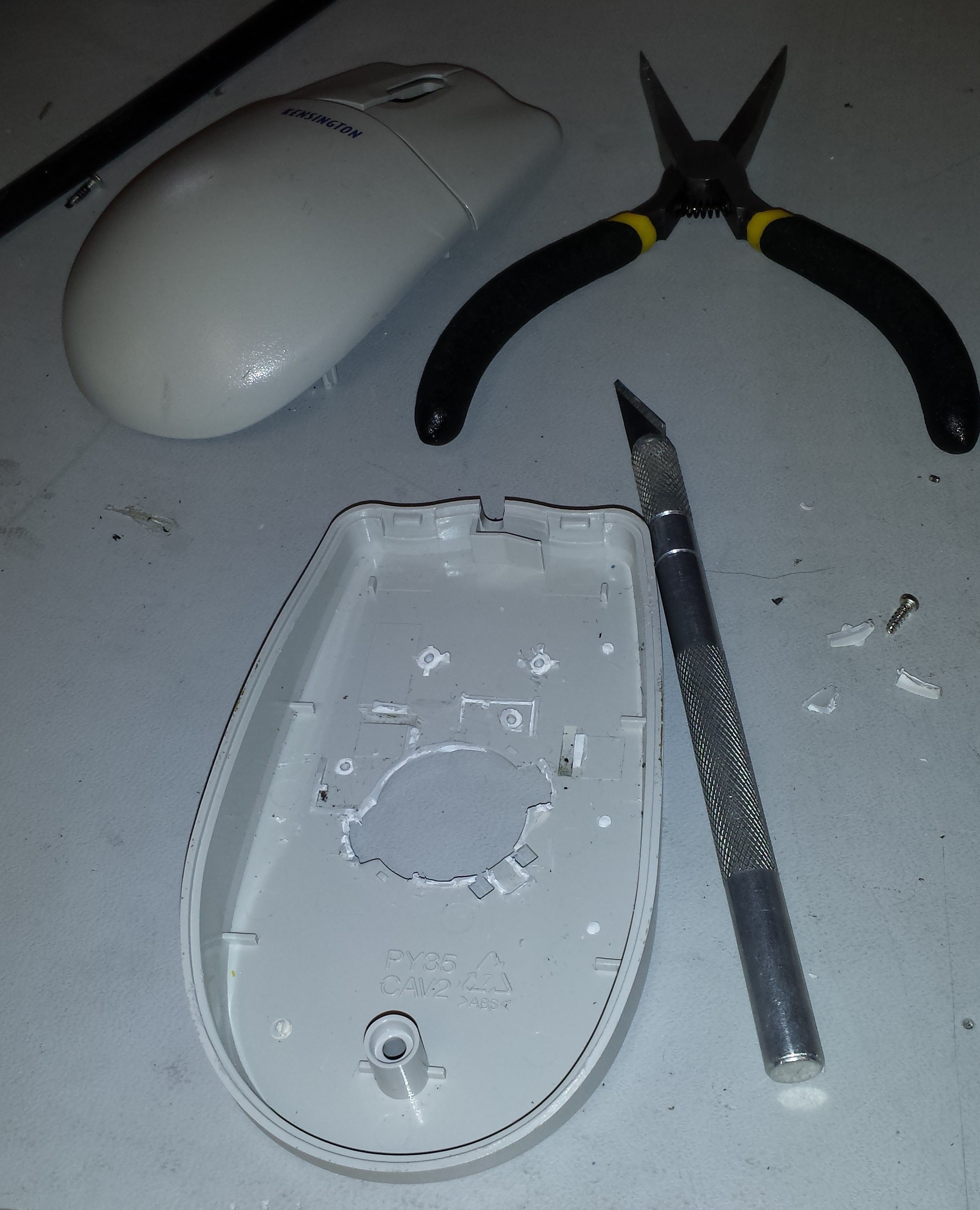 The end result of clearing out the plastic features is above. Next, I cut out some of the plastic brackets holding the buttons in place. I toyed with the idea of leaving the buttons off, but I decided to keep them to retain a more continuous look and feel.
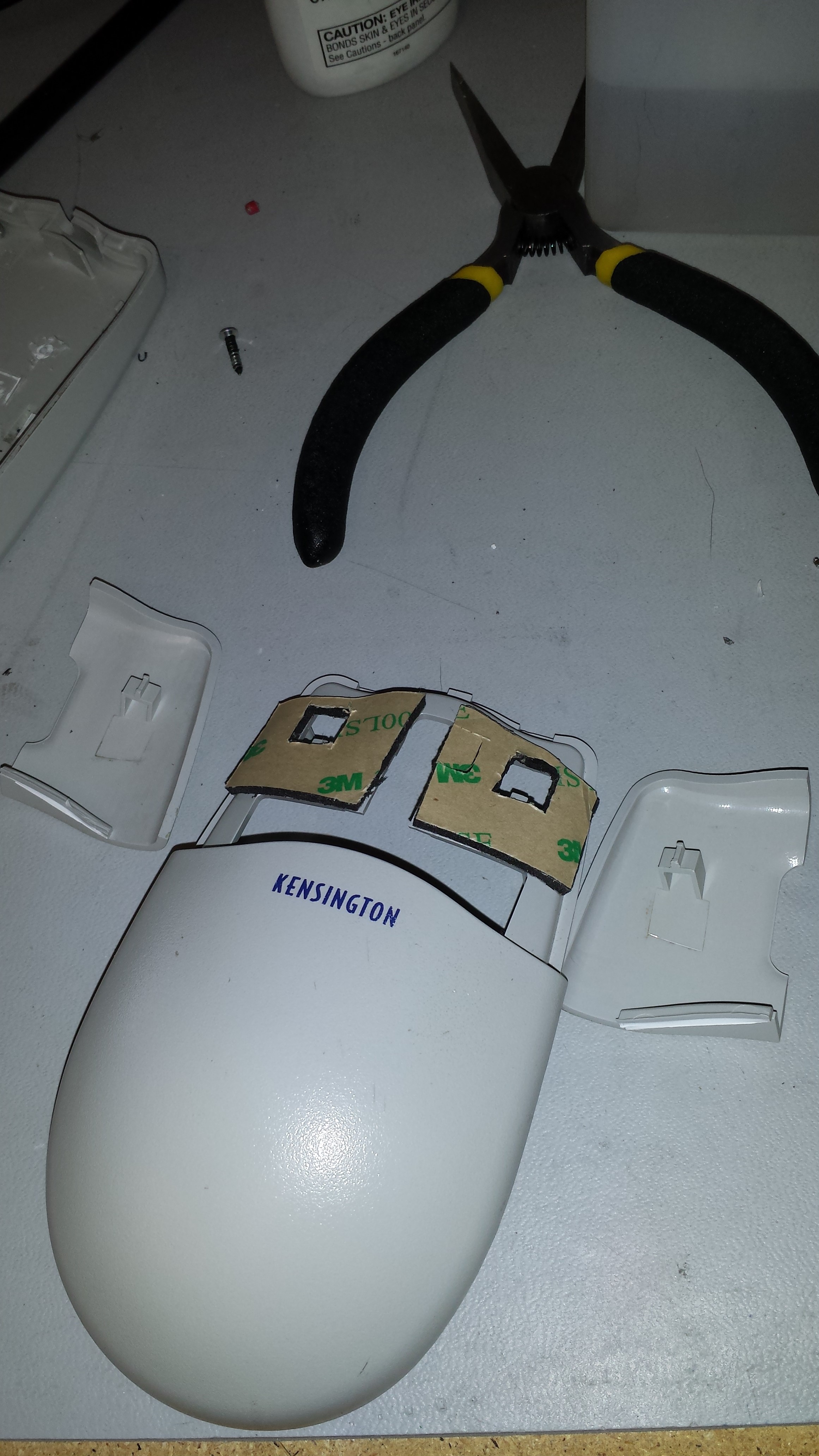 Without the supports that I chopped out, the buttons sat too low. Fortunately I had some 3M double sided sticky pads that I cut to size. As luck would have it, this spaced the height of the buttons perfectly! It also held the buttons securely to the body of the Hell Mouse.
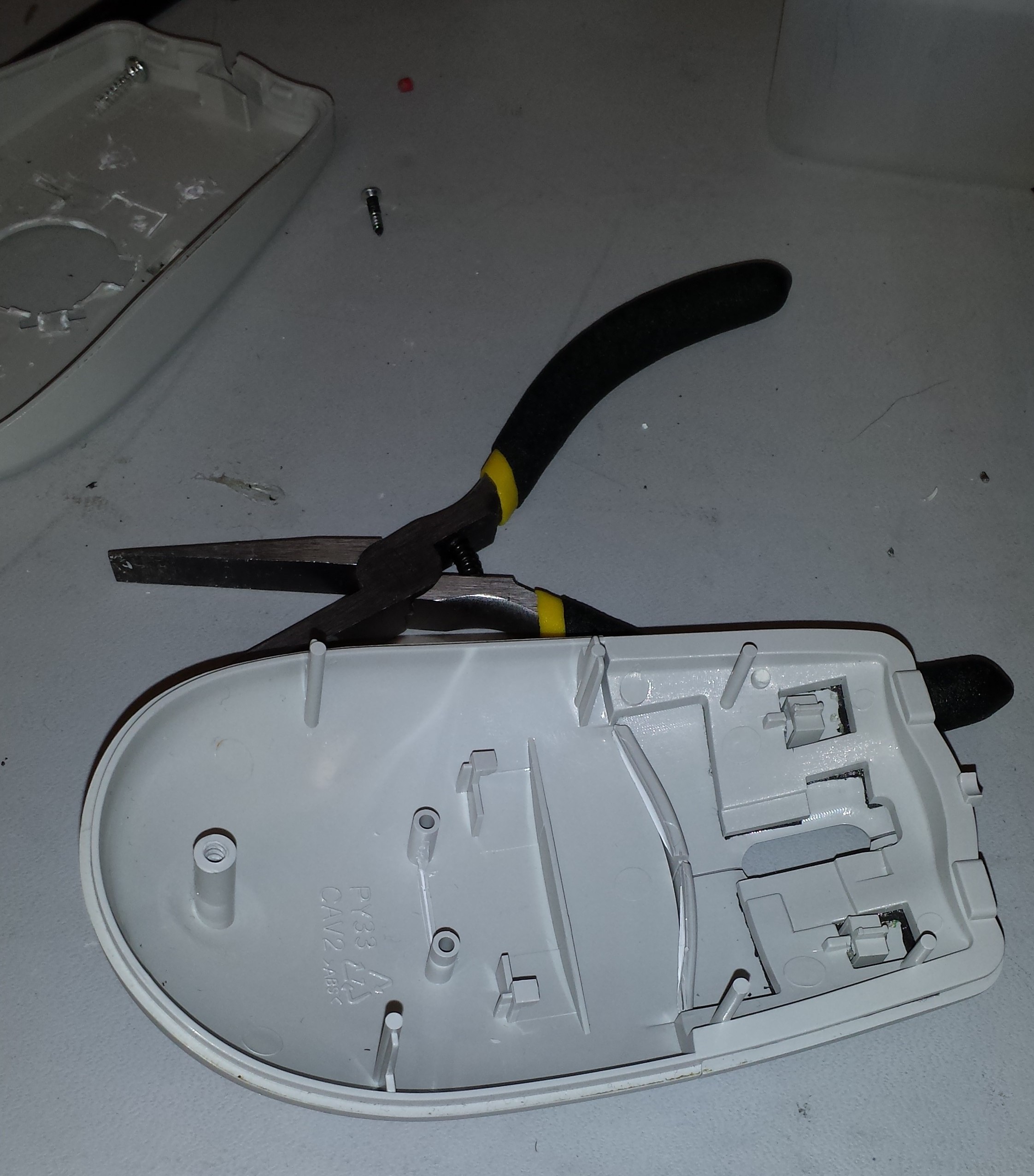 Here is a view of the underside of the top of the mouse after doing this step.
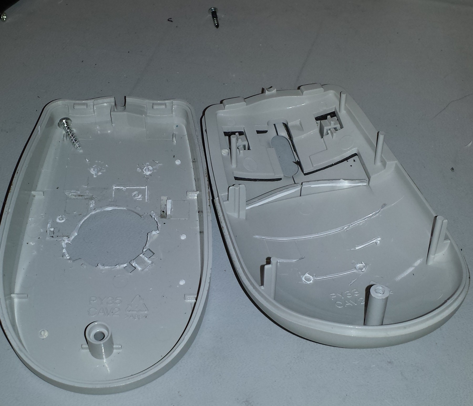 Here I cleaned out the plastic features on the top side where I will be mounting the sensor.
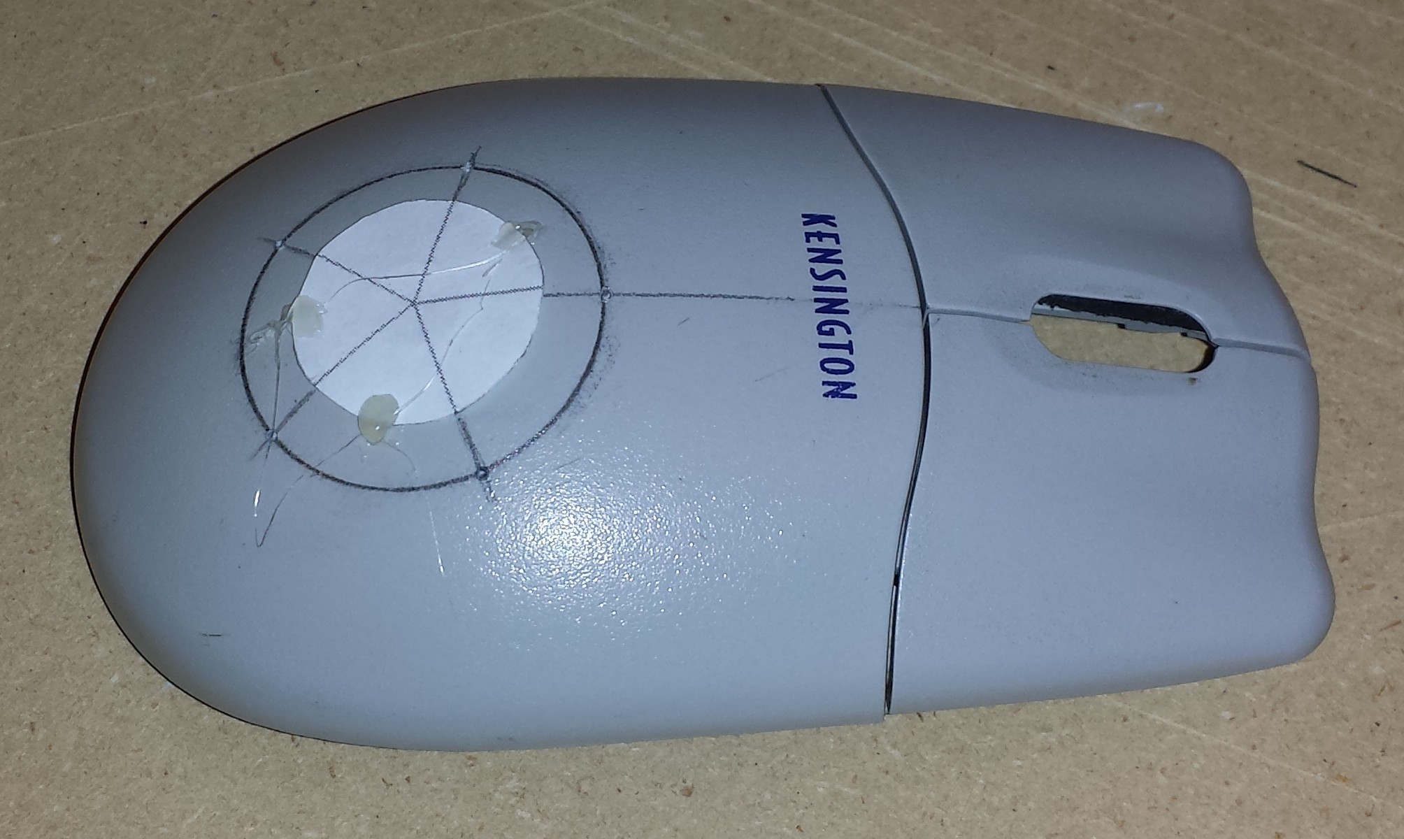 In order to space the 5 LEDs evenly, I created a quick 2D drawing in FreeCAD of a circle sliced every 72 degrees. I drew on a circle using a circle template of 1 1/4". I printed the drawing out undersized and extrapolated where to place the LEDs. I marked the center of the circle and the intersections with a punch to aid in drilling.
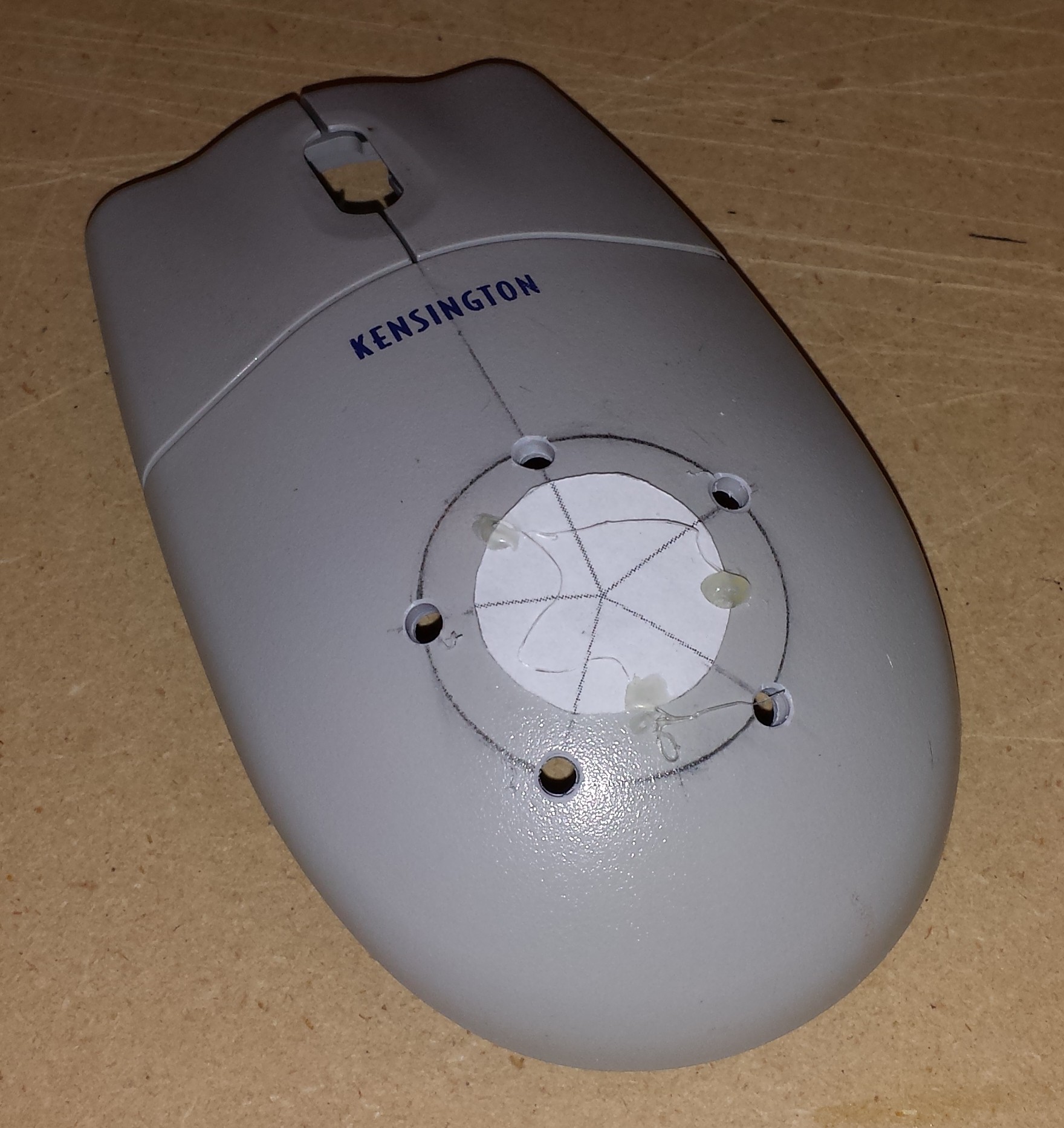 Due to the non-flat nature of this mouse, I opted to drill this using a hand drill rather than my drill press. It probably doesn't matter too much, but it seemed to work out well. I then drilled...
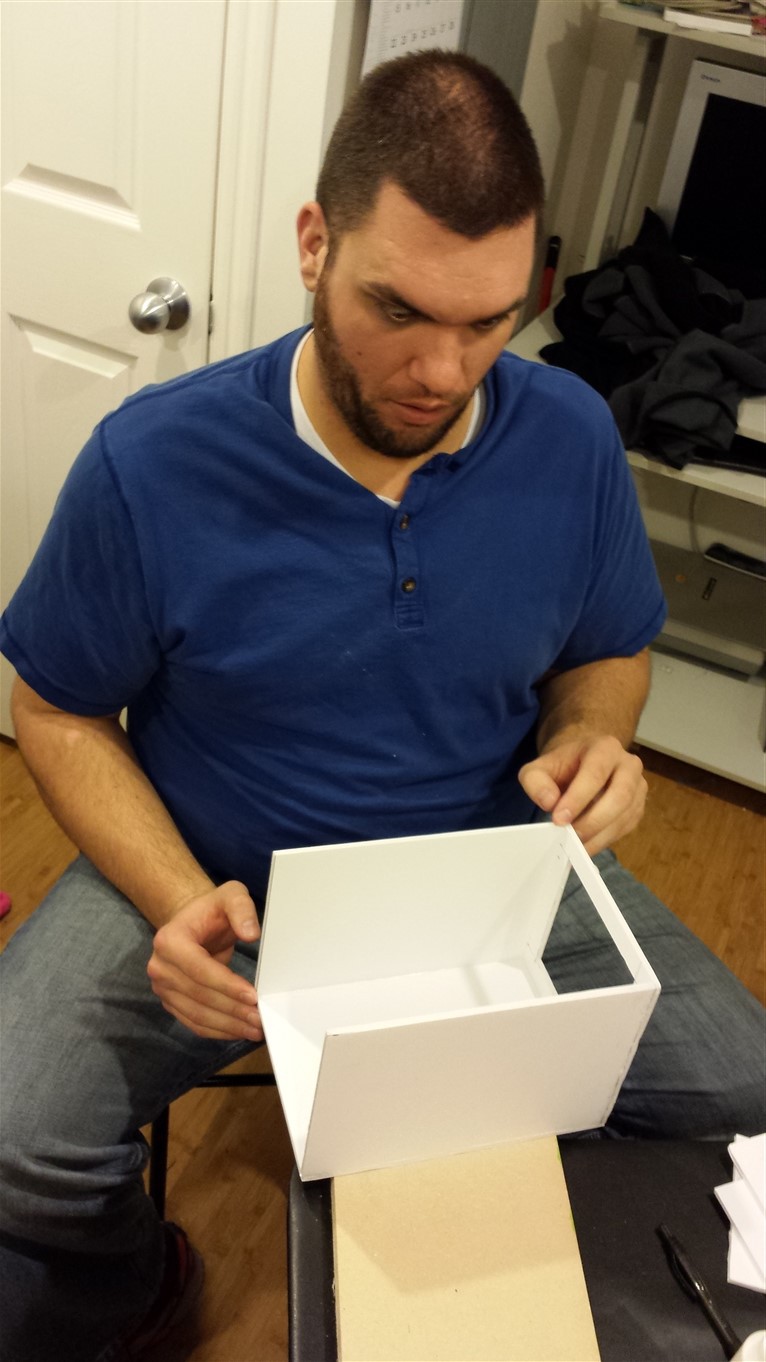
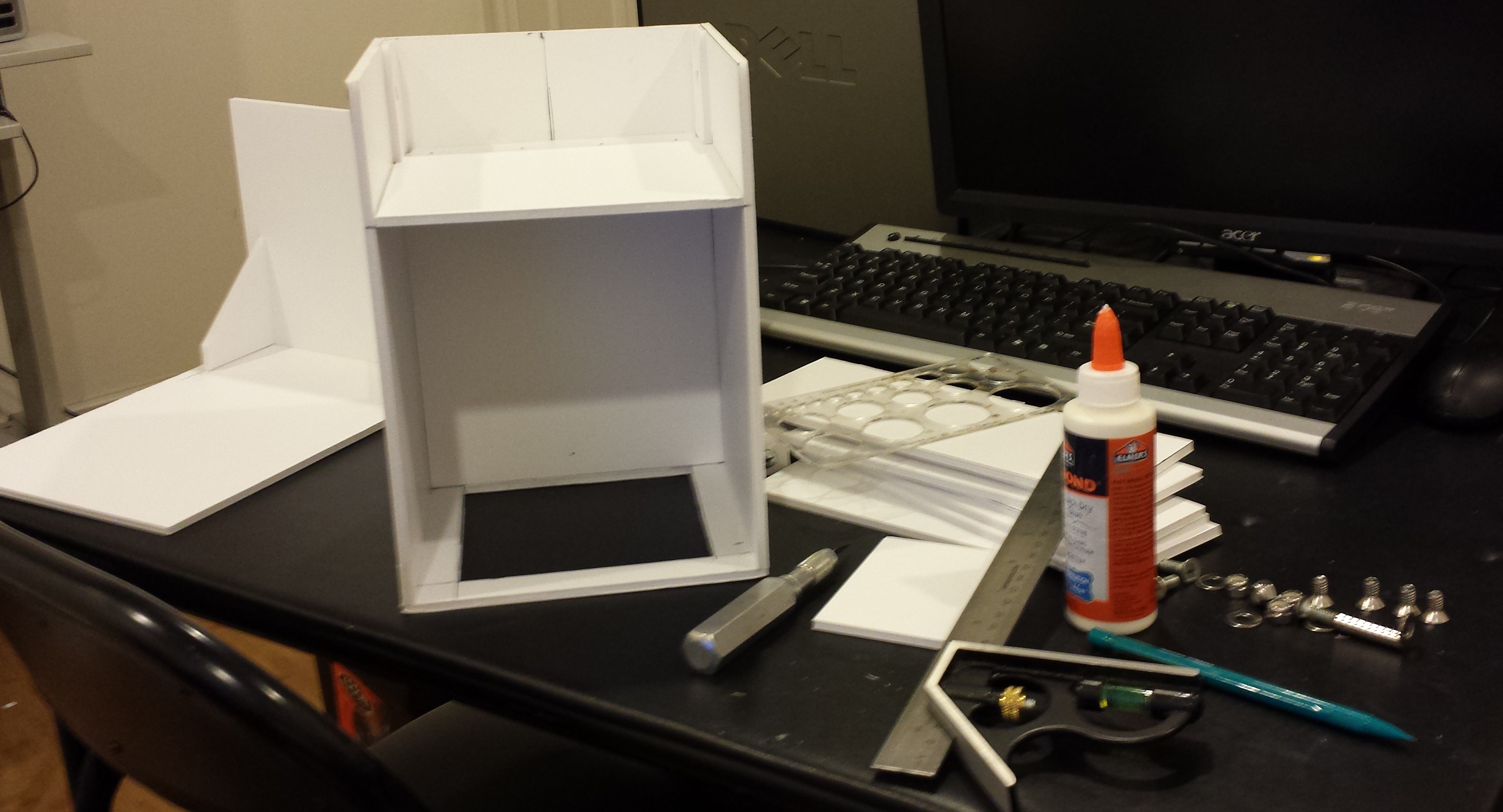 The false back can be seen here which will separate the hand part from the electronics guts of the device. The above photo also shows the cover which includes the top and back of the box. The idea is to make the cover fairly easy to remove in order to have easy access to the electronics.
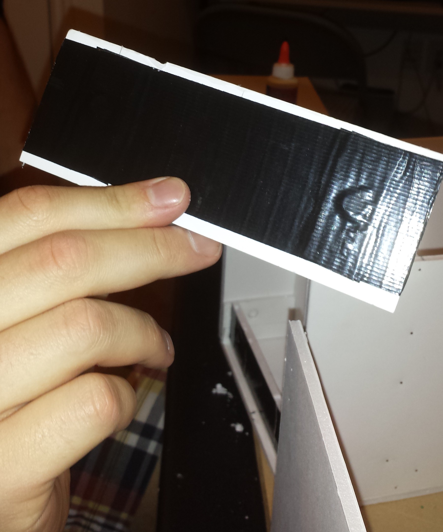
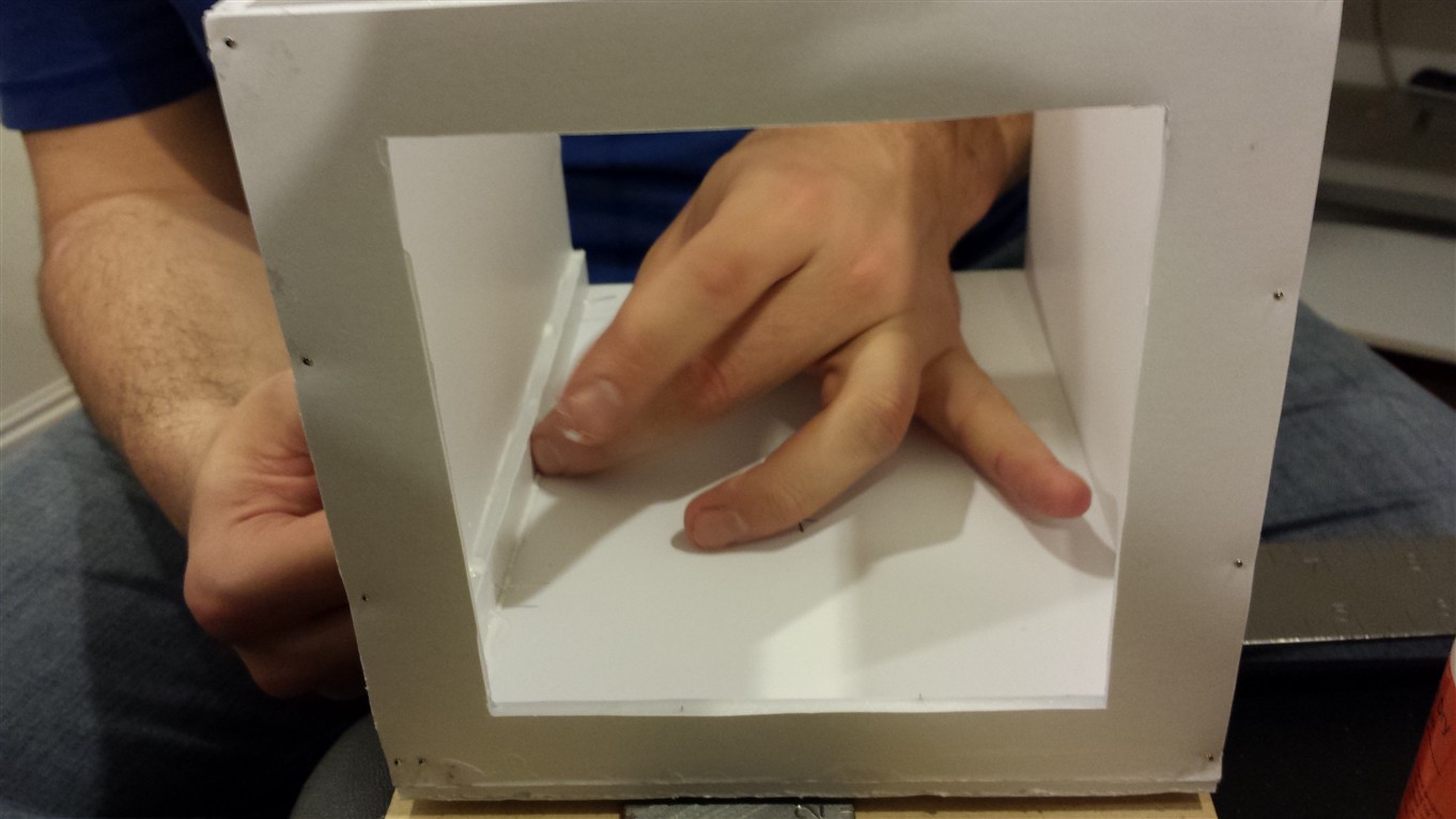
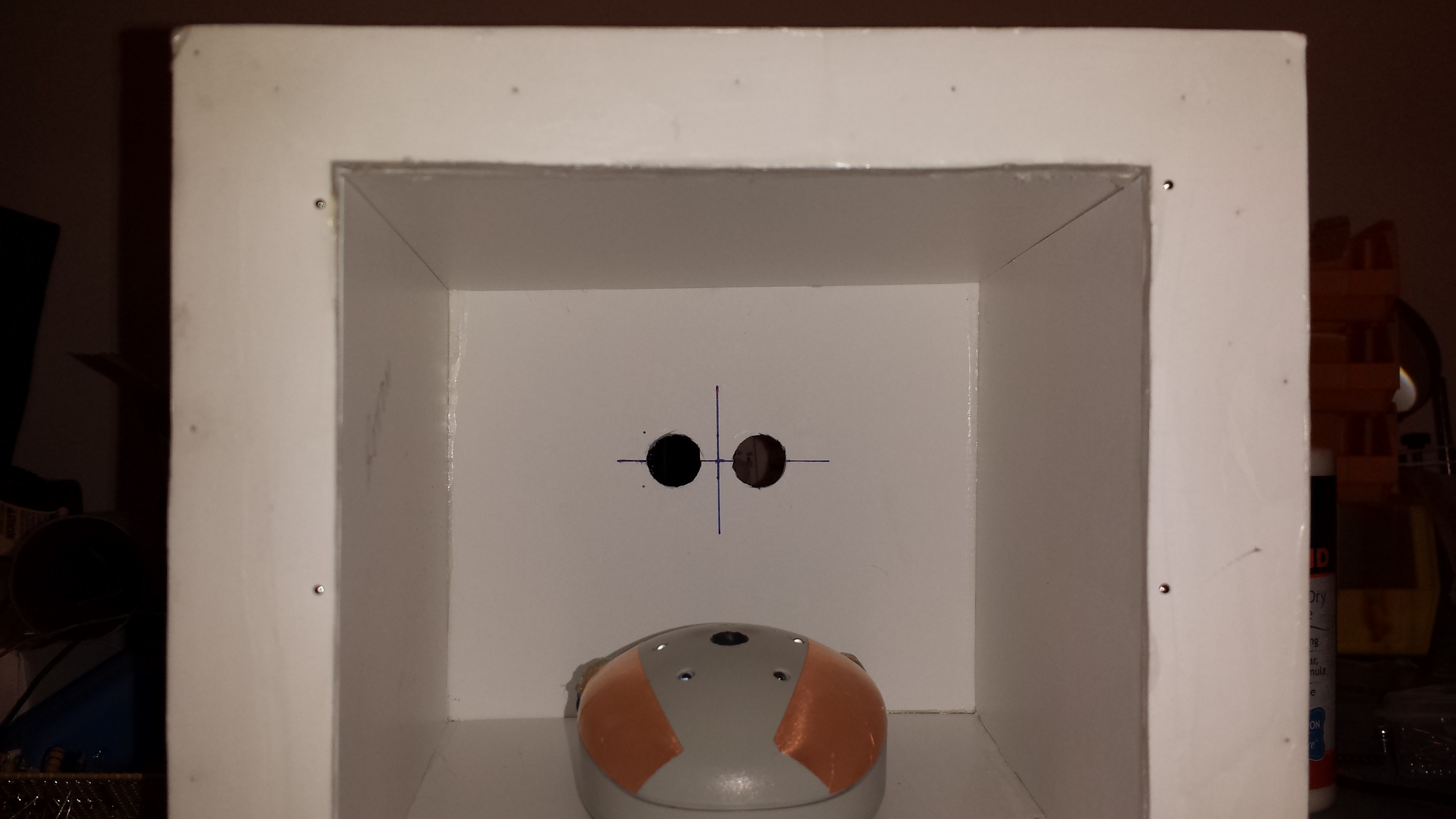 This photo shows the hand chamber boxed in with more foam core. Notice the side walls are narrower in the front and flare out in back. Also visible are the cutouts for the ultra-sonic range sensor in the back, and the hand rest. The hand rest will be covered in more depth in a separate log.
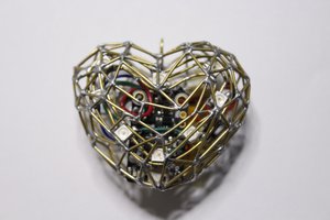
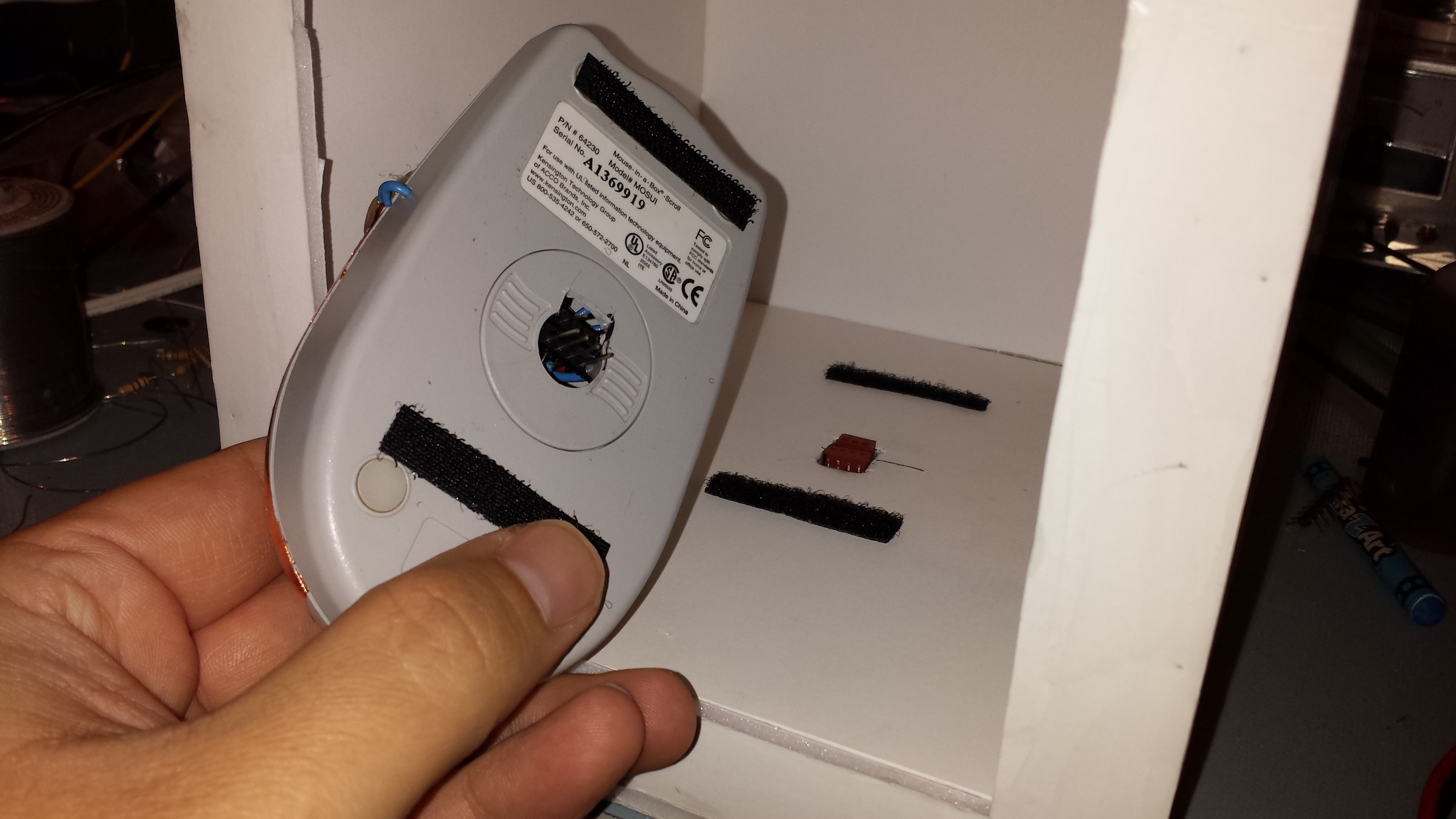 I made the hand rest removable using hook and loop strips and a couple of connectors. It may not be clear from the picture, but there are two headers glued across the opening where the ball used to go in the mouse. One is for the high voltage electrodes and the other is for the hand sensor connections. There are two mating connectors on the bottom of the box which bring out the high voltage wires and the hand sensor wires to the back. These connectors were glued in the cutout on the bottom after the hand rest was seated on them to get the height right. Again, more details on the "pain mouse" will follow in a separate post.


 BDM
BDM
 Miroslav Zuzelka
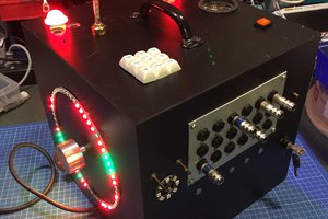
 iSax
iSax