x3n0x
x3n0x-
VIOLA! It works! Behold the Video!
04/30/2014 at 03:36 • 0 commentsWell, after some crunching, we finally got the thing cobbled together and working! The concept is proven! Future stuff would include a proper Facsimile of the Movie Prop, complete with paint, and maybe a more polished looking electrode. Also, that annoying GITHUB thing... Cant Post code, etc here! We will get that up as soon as we can... In the meantime, behold the pain box in all its glory:
Comment below and let us know what you think...
-
The Hand Thingie (aka the Hell Mouse)
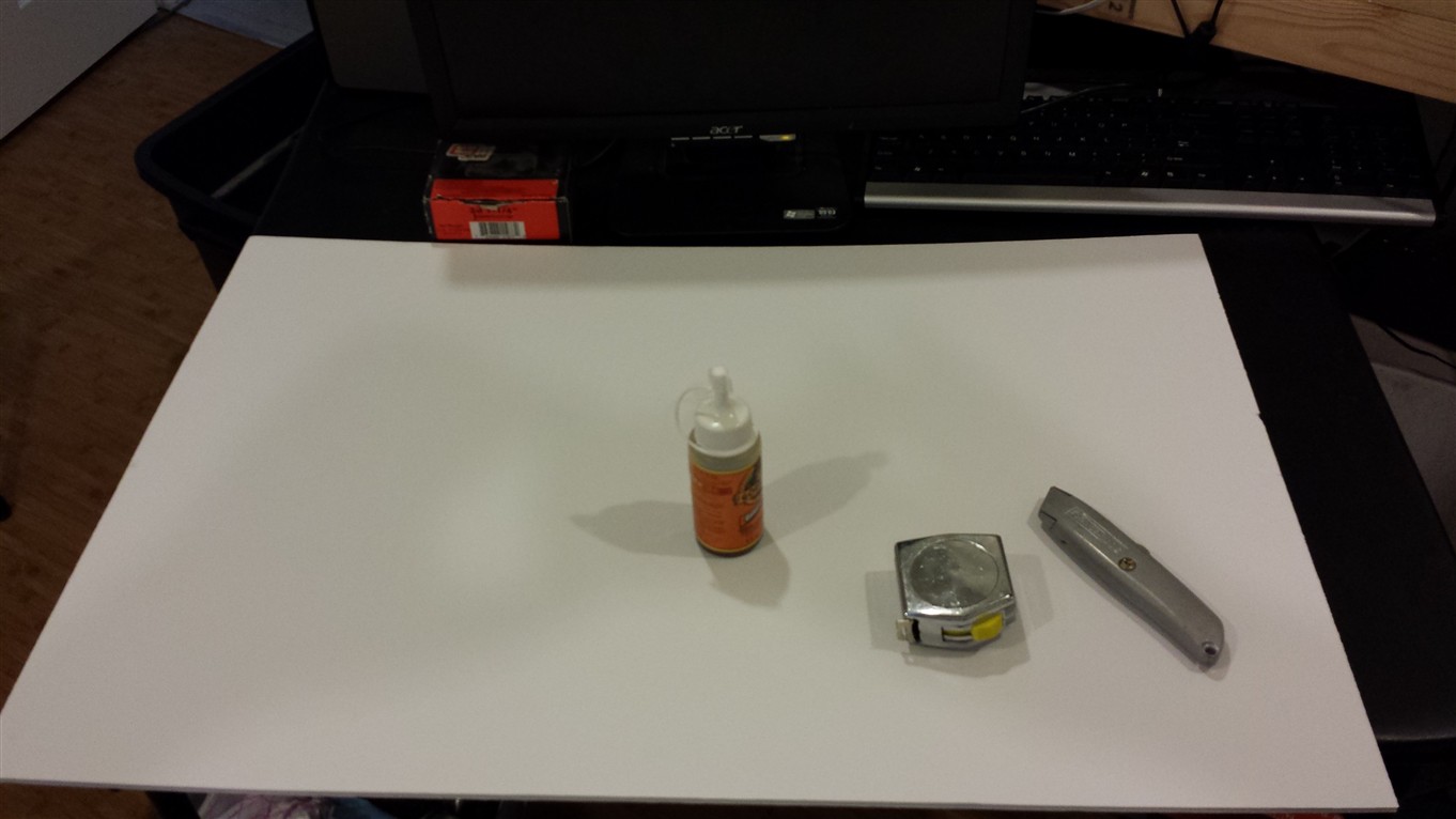
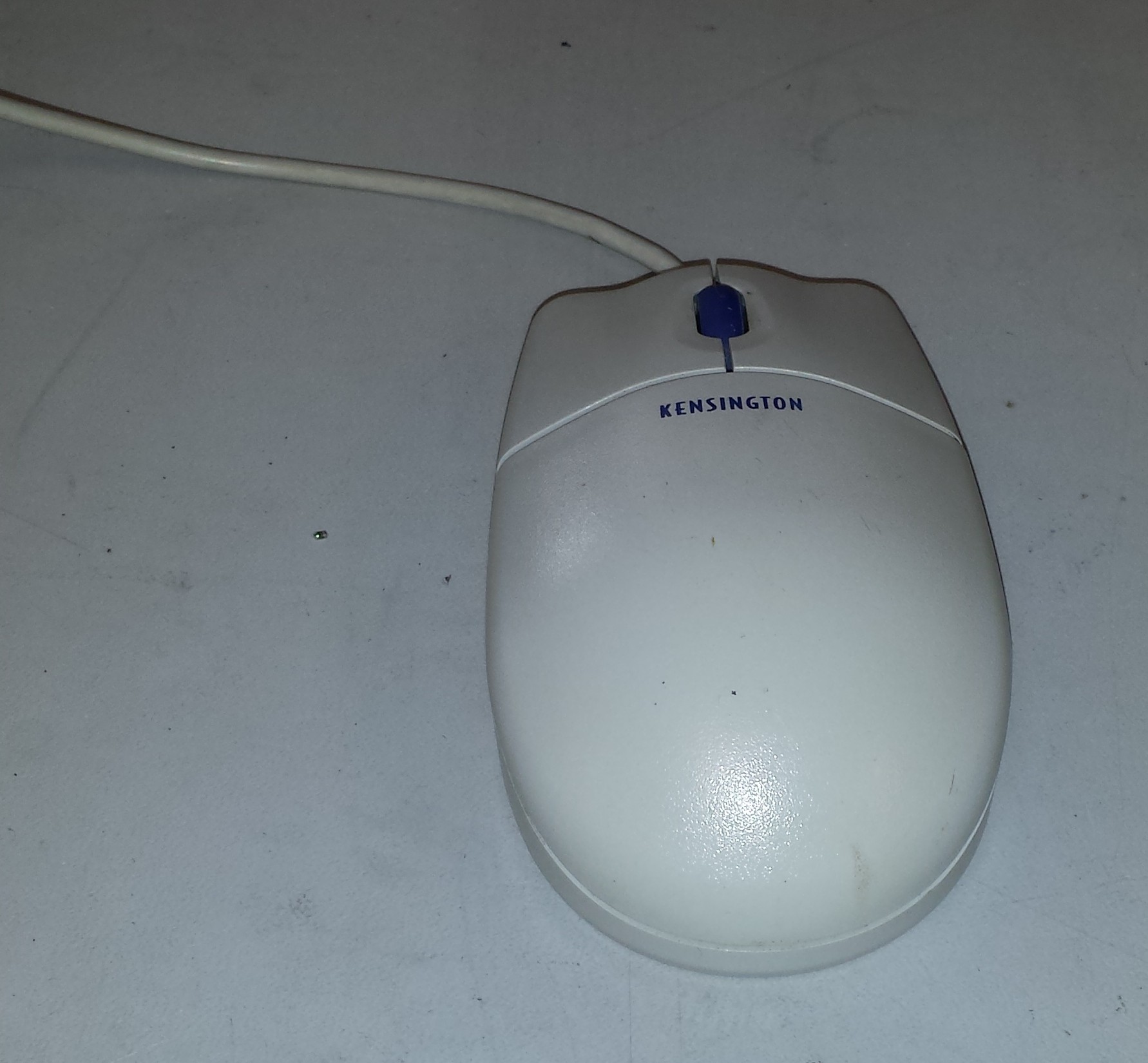
04/29/2014 at 07:50 • 2 commentsWhen trying to think of a good way to sense the hand and apply the high voltage pain / fun, [x3n0x] and I [Big Joe] went through a couple of iterations. We first thought of just putting copper traces on the bottom of the box, but we decided against that. Putting your hand on a flat surface didn't sound very comfortable. (Just because we are inducing high voltage pain, doesn't mean that we shouldn't try to make it more comfortable and ergonomic.) I wondered what we could use to house the electrodes that would be fairly comfortable for the participants to put their hand on. The idea came to me to use an old mouse. [x3n0x] liked the idea and was able to find an old PS/2 Kensington ball mouse in his junk box for use in our project.
![]() Here is our victim.
Here is our victim.For the hand sensing part, [x3n0x] at first tried to use the electrodes and measure skin resistance. The idea was to switch between sensing and shocking using a relay. We decided against it for a few reasons. The circuit he developed worked pretty well at detecting a touch on the sensor input lines, but detecting a release proved more difficult. He probably could have got the touch release working, but I was concerned about the variations in skin resistance making it difficult for this to work reliably.
[x3n0x] came up with the idea to embed a CDS cell light sensor in the middle of the mouse, surrounded by a ring of ultra-bright LEDs. If the participant placed their hand above the mouse attempting to cheat the test by not actually touching the Hell Mouse, the light from the LEDs would reflect off of the participant's hand and hit the sensor. Thereby letting the Reverend Mother know that the participant is a filthy cheater and she can dispose of them accordingly. Like wise if no hand was placed in the box, then the light would reflect from the top of the hand chamber to the CDS cell.
I really liked this idea. It also has the benefit of an ominous glow coming out of the box during the test. [x3n0x] supplied me with 5 3mm ultra-bright red LEDs (or so he thought at the time) and I got to work hacking the innocuous, obsolete Kensington mouse into the Hell Mouse.
![]() First thing on the agenda is open the thing up and pull out its guts. A single screw (seen in the photo above) is the only thing holding this thing together. I clipped off the cord and pulled the PCB and ball out leaving me with the above.
First thing on the agenda is open the thing up and pull out its guts. A single screw (seen in the photo above) is the only thing holding this thing together. I clipped off the cord and pulled the PCB and ball out leaving me with the above.![]() Next, I needed to clear out some of the plastic bosses and other features to make room for the Hell Mouse guts. My method was to score the bottom of the plastic feature I was trying to remove and snap it off using a pair of needle nose pliers.
Next, I needed to clear out some of the plastic bosses and other features to make room for the Hell Mouse guts. My method was to score the bottom of the plastic feature I was trying to remove and snap it off using a pair of needle nose pliers.![]() The end result of clearing out the plastic features is above. Next, I cut out some of the plastic brackets holding the buttons in place. I toyed with the idea of leaving the buttons off, but I decided to keep them to retain a more continuous look and feel.
The end result of clearing out the plastic features is above. Next, I cut out some of the plastic brackets holding the buttons in place. I toyed with the idea of leaving the buttons off, but I decided to keep them to retain a more continuous look and feel.![]() Without the supports that I chopped out, the buttons sat too low. Fortunately I had some 3M double sided sticky pads that I cut to size. As luck would have it, this spaced the height of the buttons perfectly! It also held the buttons securely to the body of the Hell Mouse.
Without the supports that I chopped out, the buttons sat too low. Fortunately I had some 3M double sided sticky pads that I cut to size. As luck would have it, this spaced the height of the buttons perfectly! It also held the buttons securely to the body of the Hell Mouse.![]() Here is a view of the underside of the top of the mouse after doing this step.
Here is a view of the underside of the top of the mouse after doing this step.![]() Here I cleaned out the plastic features on the top side where I will be mounting the sensor.
Here I cleaned out the plastic features on the top side where I will be mounting the sensor.![]() In order to space the 5 LEDs evenly, I created a quick 2D drawing in FreeCAD of a circle sliced every 72 degrees. I drew on a circle using a circle template of 1 1/4". I printed the drawing out undersized and extrapolated where to place the LEDs. I marked the center of the circle and the intersections with a punch to aid in drilling.
In order to space the 5 LEDs evenly, I created a quick 2D drawing in FreeCAD of a circle sliced every 72 degrees. I drew on a circle using a circle template of 1 1/4". I printed the drawing out undersized and extrapolated where to place the LEDs. I marked the center of the circle and the intersections with a punch to aid in drilling.![]() Due to the non-flat nature of this mouse, I opted to drill this using a hand drill rather than my drill press. It probably doesn't matter too much, but it seemed to work out well. I then drilled out the larger hole for the CDS sensor with a short length of heat shrink tubing to block ambient light.
Due to the non-flat nature of this mouse, I opted to drill this using a hand drill rather than my drill press. It probably doesn't matter too much, but it seemed to work out well. I then drilled out the larger hole for the CDS sensor with a short length of heat shrink tubing to block ambient light.![]()
This is the sensor circuit inside the mouse. I opted to do point to point wiring since this circuitry is pretty simple.
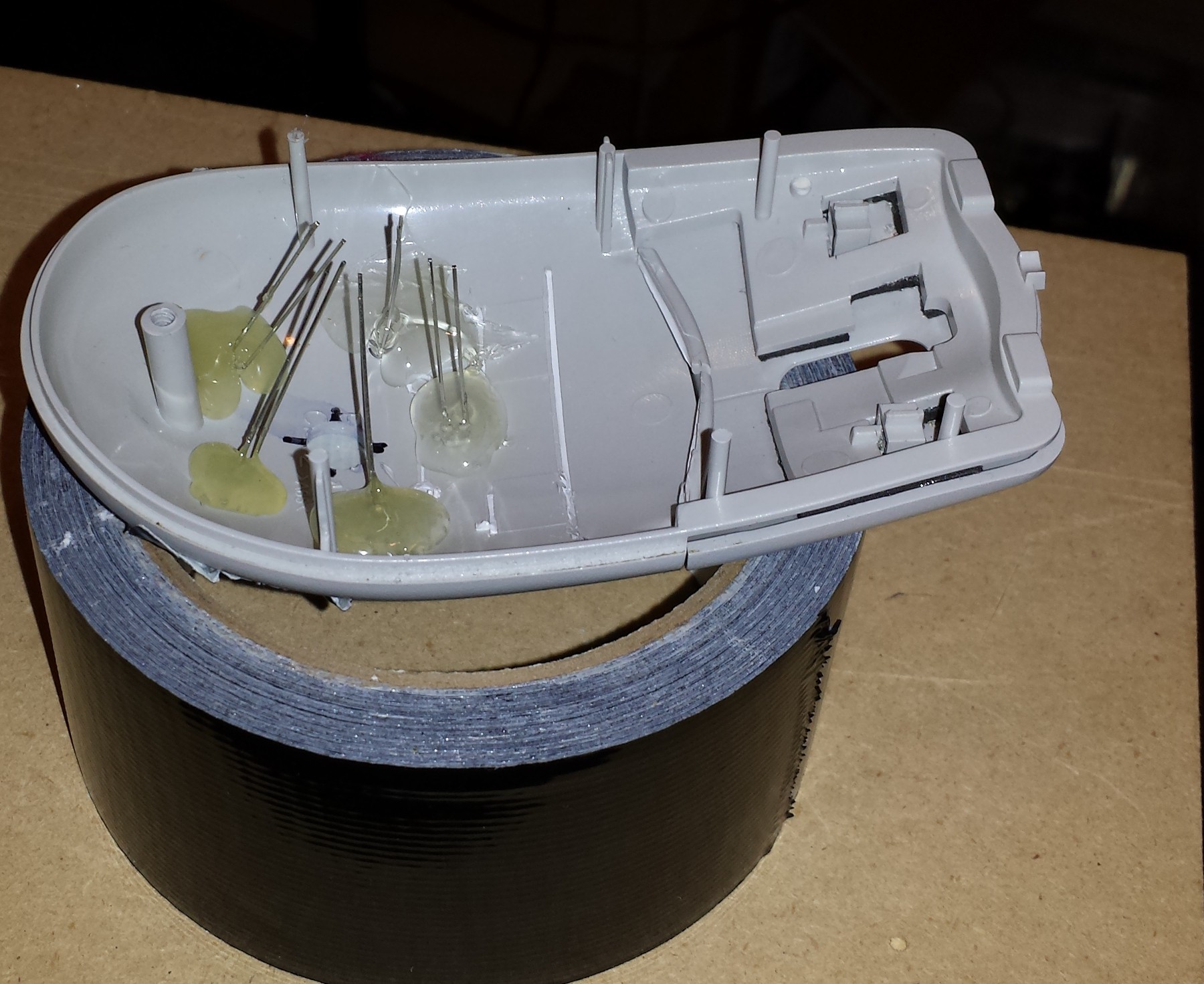
![]() The LEDs were glued in place. I made all of the LEDs anodes face inwards since they are all connected together. (Yes that is a roll of duct tape holding the mouse so I can work on it.)
The LEDs were glued in place. I made all of the LEDs anodes face inwards since they are all connected together. (Yes that is a roll of duct tape holding the mouse so I can work on it.)![]() I'm using a small piece of protoboard to help hold the CDS cell in place. I then built up hot glue around the protoboard.
I'm using a small piece of protoboard to help hold the CDS cell in place. I then built up hot glue around the protoboard.![]() Here is the first of two headers glued in to the bottom of the mouse. The box will have mating connectors embedded in the bottom that will interface the Hell Mouse to the rest of the electronics.
Here is the first of two headers glued in to the bottom of the mouse. The box will have mating connectors embedded in the bottom that will interface the Hell Mouse to the rest of the electronics.![]() I wired this clam shell style so it could be easily opened and accessed if needed.
I wired this clam shell style so it could be easily opened and accessed if needed.![]() The second header for the high voltage electrodes is shown above with the blue wires. A normal 0.1" header was used. The middle pin was pulled out to give the high voltage wires some distance from one another. I have a video (which I will upload later) of this sensor being tested and it seems to work great!
The second header for the high voltage electrodes is shown above with the blue wires. A normal 0.1" header was used. The middle pin was pulled out to give the high voltage wires some distance from one another. I have a video (which I will upload later) of this sensor being tested and it seems to work great!![]() [x3n0x] applied some strips of adhesive backed copper foil to the Hell Mouse. I ran wires from the high voltage header to each side and tacked it on with solder. Unfortunately the stupid copper foil started peeling off and threatening to rip, so I had to tack it down with a ugly glob of hot glue. Other than the hot glue globs, this thing is looking pretty good so far!
[x3n0x] applied some strips of adhesive backed copper foil to the Hell Mouse. I ran wires from the high voltage header to each side and tacked it on with solder. Unfortunately the stupid copper foil started peeling off and threatening to rip, so I had to tack it down with a ugly glob of hot glue. Other than the hot glue globs, this thing is looking pretty good so far!![]() Trying out the fit of the connectors to the headers. I had to cut out a chunk of plastic so the high voltage connector could get fully seated to the header. This wire harness will be integrated into the bottom of the pain box.
Trying out the fit of the connectors to the headers. I had to cut out a chunk of plastic so the high voltage connector could get fully seated to the header. This wire harness will be integrated into the bottom of the pain box.![]() I added 2 narrow strips of hook and loop to the Hell Mouse to help hold it down securely, yet remain removable. I was afraid the hook and loop strips would tear off the foam core, but the few test disconnections showed it was working perfectly.
I added 2 narrow strips of hook and loop to the Hell Mouse to help hold it down securely, yet remain removable. I was afraid the hook and loop strips would tear off the foam core, but the few test disconnections showed it was working perfectly.![]() Here is the little beast installed in the box, ready to assist the Reverend Mother in testing for animals.
Here is the little beast installed in the box, ready to assist the Reverend Mother in testing for animals. -
HA! The code works great!
04/29/2014 at 06:41 • 0 commentsWell, after some fumbling, the code works great! Cutting close is an undertstatement! Fine tuning and stuff with the box and all the crap inside will be finished tomorrow! We will post video, and finalize the uploads and instructions in a nick of time! Whew!
-
The Box Completed (sort of)
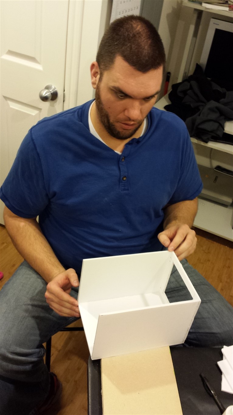
04/29/2014 at 05:35 • 0 commentsOn the last update on the box it was starting to take shape, but was far from complete. The goal with this box was not to get an exact replica of the movie prop. Rather, due to time constraints, it was decided to at least get a reasonable approximation of the prop.
![]() The false back can be seen here which will separate the hand part from the electronics guts of the device. The above photo also shows the cover which includes the top and back of the box. The idea is to make the cover fairly easy to remove in order to have easy access to the electronics.
The false back can be seen here which will separate the hand part from the electronics guts of the device. The above photo also shows the cover which includes the top and back of the box. The idea is to make the cover fairly easy to remove in order to have easy access to the electronics.![]()
In order to keep the cover on the box, I decided to use small rare earth magnets to snap the cover in place. When I tested out the strength of the magnet to magnet bond, it was too strong. [Afro Spock] was concerned that removing the cover when the magnets were so strong could rip the box apart. We found through experimentation that 3 layers of duct tape on each magnet reduced the intensity of the bond just enough, while still retaining quite a bit of strength. Our method of embedding the magnets involved cutting out a properly sized, round hole in the foam core, pushing the magnet in the foam core, and covering it with duct tape. Keep in mind the magnetic polarity when embedding the mating magnet. Test it out before committing with tape or glue! (Don't ask...)
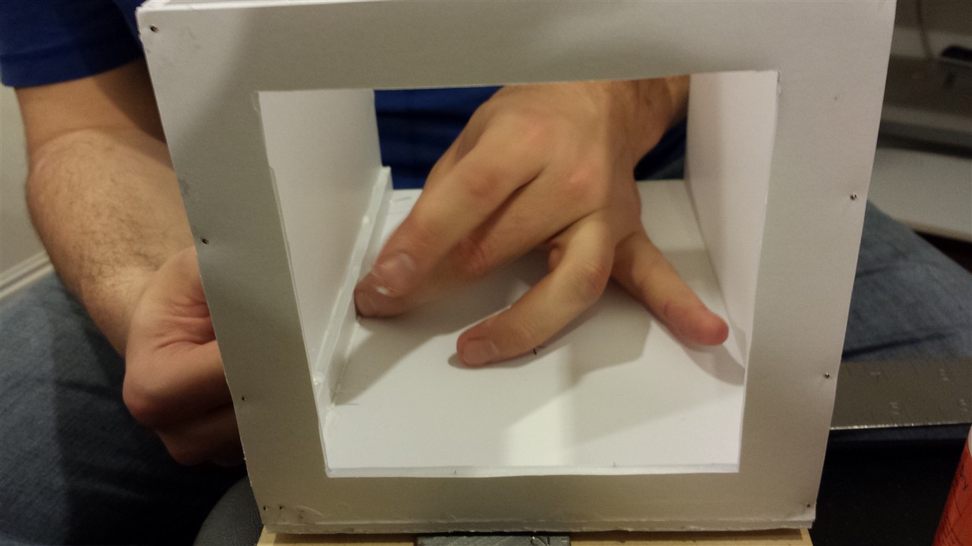
The cut out for the victim / participant's hand is over sized from the proportions of the prop on purpose. (My brother [Afro Spock] and I [Big Joe] have big ham hands.) Once the hand cutout was complete we boxed in the interior of the hand chamber so the ultra-sonic sensor wouldn't get false pings from a lip. The sides flare out in the back to the inside of the exterior walls and come closer together at the front, where they are flush with the front hand cutout.
![]() This photo shows the hand chamber boxed in with more foam core. Notice the side walls are narrower in the front and flare out in back. Also visible are the cutouts for the ultra-sonic range sensor in the back, and the hand rest. The hand rest will be covered in more depth in a separate log.
This photo shows the hand chamber boxed in with more foam core. Notice the side walls are narrower in the front and flare out in back. Also visible are the cutouts for the ultra-sonic range sensor in the back, and the hand rest. The hand rest will be covered in more depth in a separate log.![]() I made the hand rest removable using hook and loop strips and a couple of connectors. It may not be clear from the picture, but there are two headers glued across the opening where the ball used to go in the mouse. One is for the high voltage electrodes and the other is for the hand sensor connections. There are two mating connectors on the bottom of the box which bring out the high voltage wires and the hand sensor wires to the back. These connectors were glued in the cutout on the bottom after the hand rest was seated on them to get the height right. Again, more details on the "pain mouse" will follow in a separate post.
I made the hand rest removable using hook and loop strips and a couple of connectors. It may not be clear from the picture, but there are two headers glued across the opening where the ball used to go in the mouse. One is for the high voltage electrodes and the other is for the hand sensor connections. There are two mating connectors on the bottom of the box which bring out the high voltage wires and the hand sensor wires to the back. These connectors were glued in the cutout on the bottom after the hand rest was seated on them to get the height right. Again, more details on the "pain mouse" will follow in a separate post.That's basically it for the box. I had planned to glue some trim to it and paint it to look more like the prop, but I ran out of time. As I said earlier, it's a crude, but reasonable approximation of the movie prop. There isn't really anything too critical about this box and there are plenty of other superior ways to do this. If anyone recreates this project and improves upon the box design / fabrication, we'd love to see it! Send us a link in the comments.
-
Latest Schematics !
04/28/2014 at 03:57 • 0 commentsThought I would post all the schematics in their most current form for everyone! I have posted them as JPG. Later on, I will get the PDFS up here as well.
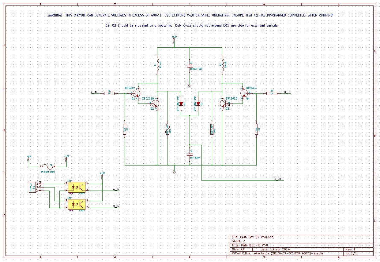
The PSU:
![]()
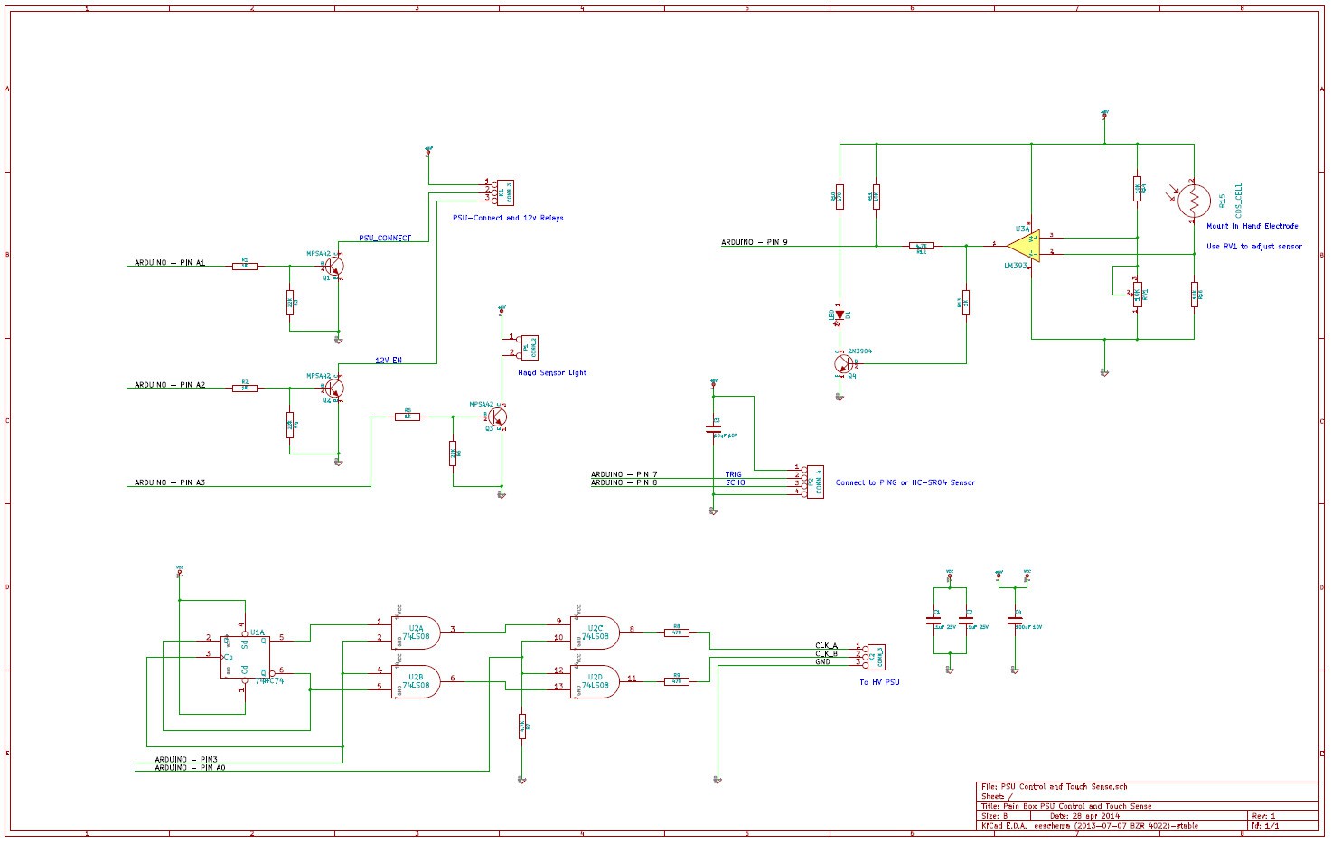
The Control Circuit:
![]()
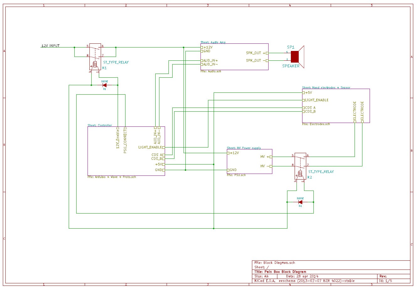
The Block diagram ( How does everything hook to the Arduino?) Sorry guys, no fritzing or anything like that. Your gonna have to read the schematics carefully...
![]()
So there it is. The code should be done by tomorrow sometime, and then we will try and get some video up. Everything is coming along pretty well!
Comment, Give skulls, and stay tuned for the final play in this project...
-
Code is Under way!!!
04/25/2014 at 04:58 • 0 commentsThe code is coming along nicely! Everything but the Ping sensor stuff is basically done! It should be complete by beginning of next week! Talk about cutting it close! The box should also be done by early next week. Then we just have to cobble it all together and finish the documentation!
-
Videos Posted! Check them out below!
04/22/2014 at 06:04 • 0 commentsThe video of the wave shield testing is up. Check them out! Comment, Give skulls, and follow to stay tuned for what is coming next!
-
Wave Shield - Take 2
04/22/2014 at 06:01 • 0 commentsSince the volume of the first test was so dismal, in part due to the poor speaker and open air conditions, I whipped up an amplifier from an LM383. 8w baby! You can sure hear it now! Oh, and I'm sure the better quality speaker and enclosure help some too... Check it out...
-
Wave Shield Testing and Audio
04/19/2014 at 21:03 • 0 commentsTesting the Wave Shield... Seems to work Good. Got some good sound clips from the movie. Video is forthcoming after I get it uploaded to youtube. This is waaaay too much fun...
Youtube video below...
-
The Box Starts to Take Shape
04/19/2014 at 17:00 • 0 commentsSo, a couple of us started making the box. It wasn't easy to find good pictures of the box as shown in the movie, and you don't get very good views of it. After some digging, we found a place that sells old movie props and they had a listing for something that looked about right. They listed dimensions, and that gave us something to start working with. We still haven't figured out how to do the columns on the front, but so far, it looks like it will work well. There is a lot of room in he back for the electronics, and after it gets painted and trimmed, it should look the part pretty well. Here are some pictures of the progress:
![]()
Here is the foam board, ready to 'go under the knife'. Foam Board and Gorrilla Glue... Yummy...
![]()
The shape begins to show. We used Pins and Glue both to make the joints to help make sure it had some strength.
![]()
Afro Spock, carefully contemplating the terrible device we are bringing to life...
 Here is our victim.
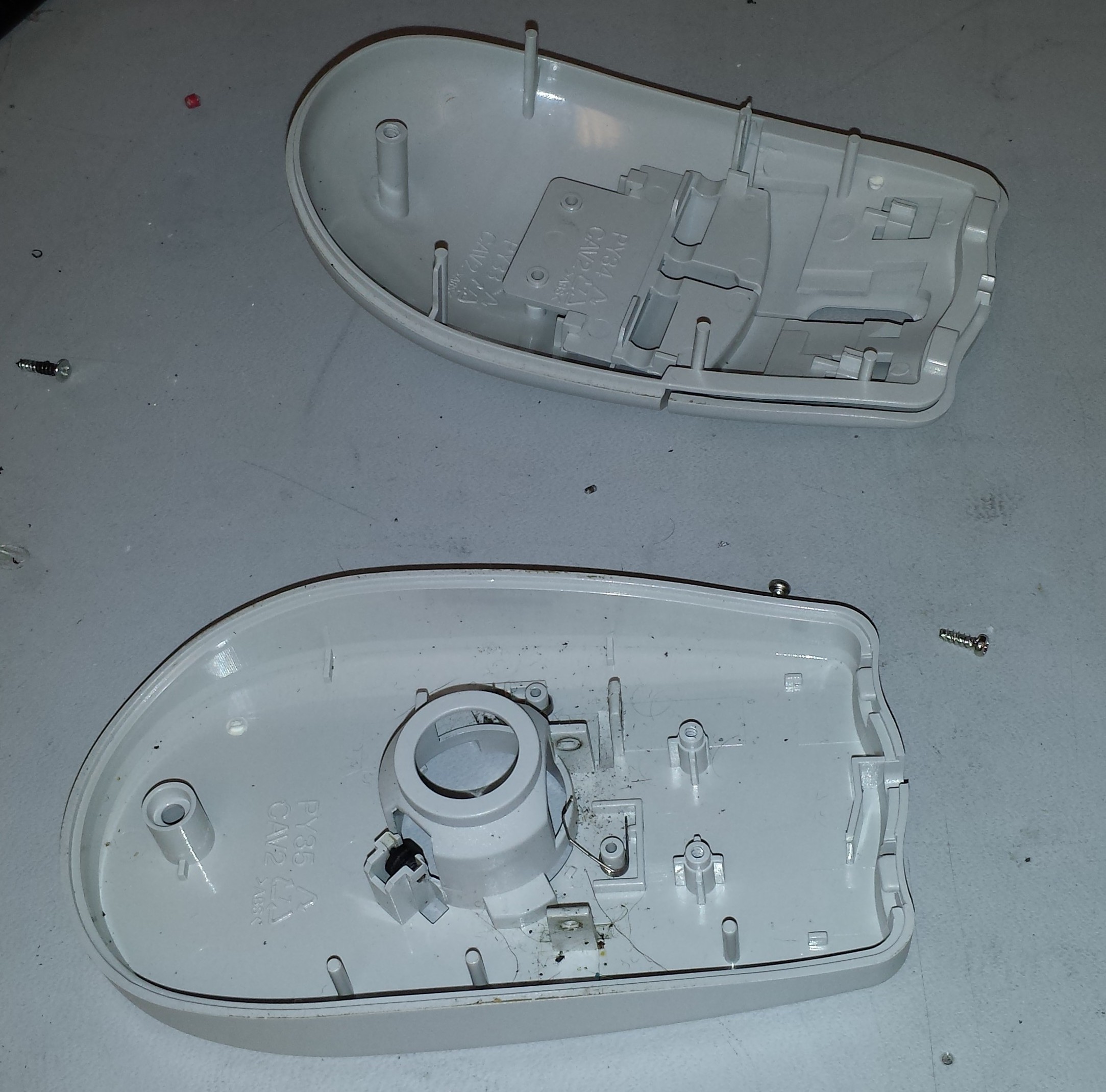 First thing on the agenda is open the thing up and pull out its guts. A single screw (seen in the photo above) is the only thing holding this thing together. I clipped off the cord and pulled the PCB and ball out leaving me with the above.
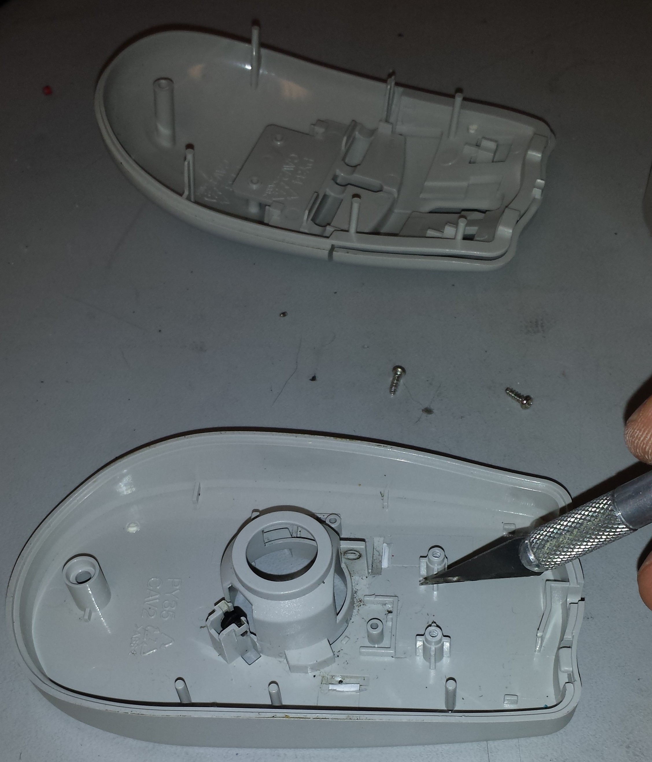 Next, I needed to clear out some of the plastic bosses and other features to make room for the Hell Mouse guts. My method was to score the bottom of the plastic feature I was trying to remove and snap it off using a pair of needle nose pliers.
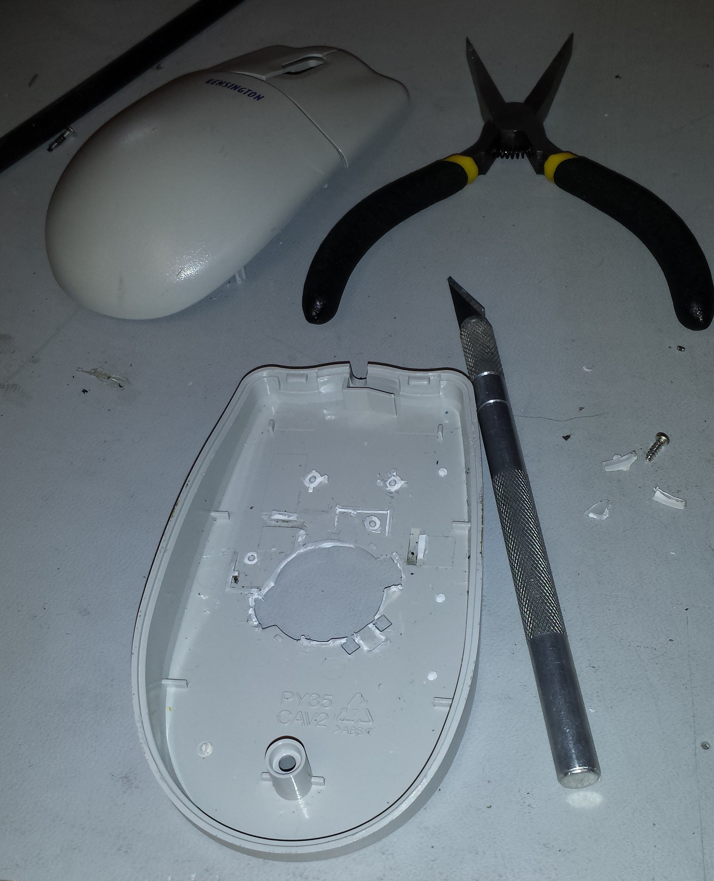 The end result of clearing out the plastic features is above. Next, I cut out some of the plastic brackets holding the buttons in place. I toyed with the idea of leaving the buttons off, but I decided to keep them to retain a more continuous look and feel.
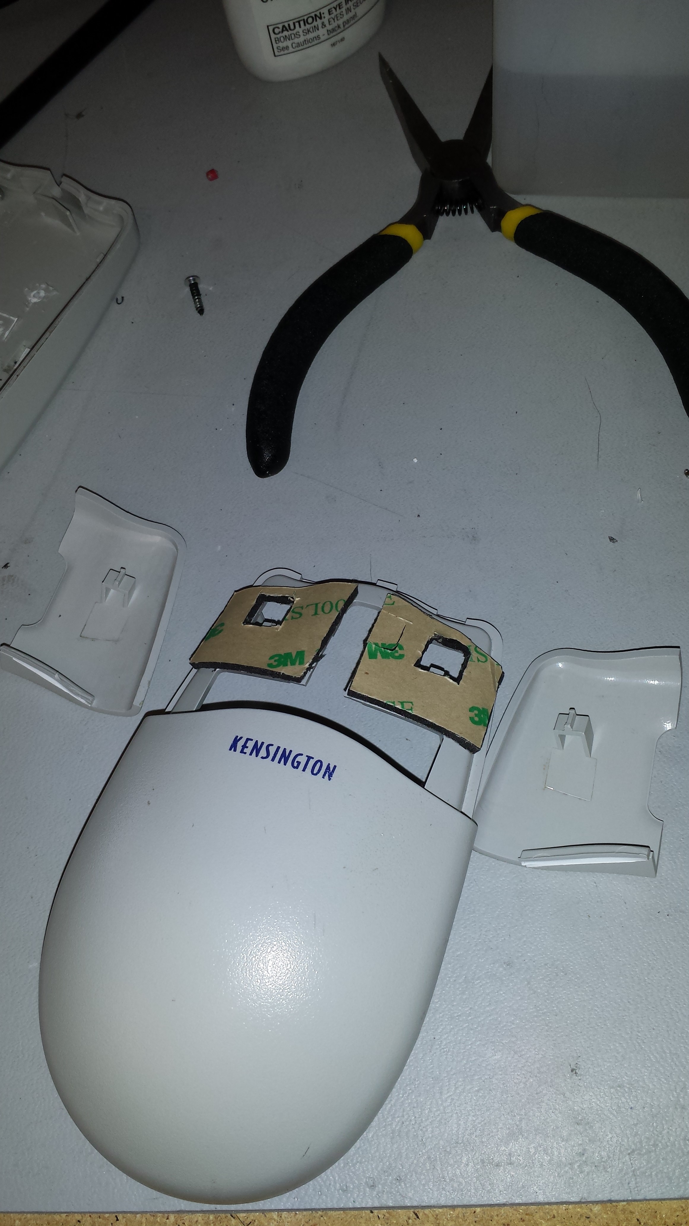 Without the supports that I chopped out, the buttons sat too low. Fortunately I had some 3M double sided sticky pads that I cut to size. As luck would have it, this spaced the height of the buttons perfectly! It also held the buttons securely to the body of the Hell Mouse.
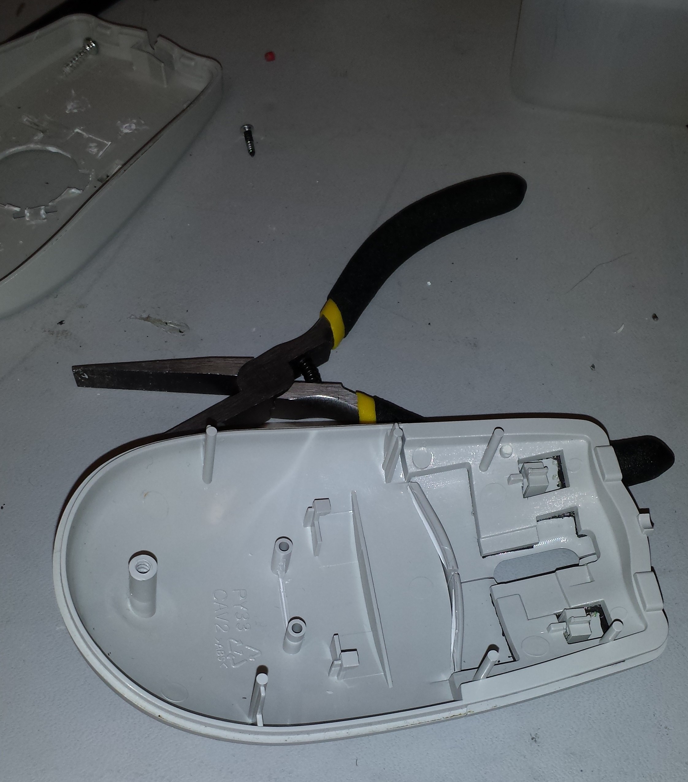 Here is a view of the underside of the top of the mouse after doing this step.
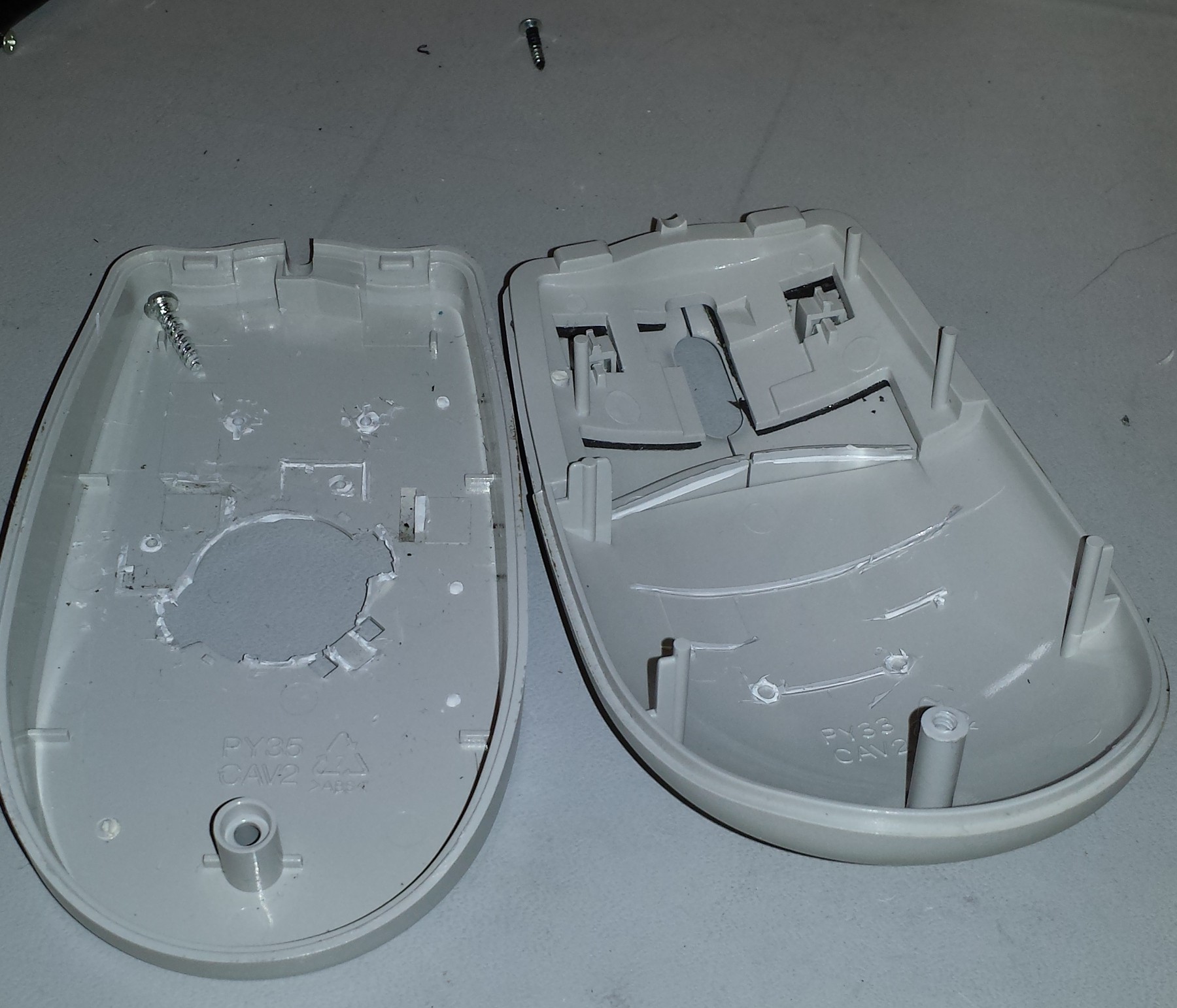 Here I cleaned out the plastic features on the top side where I will be mounting the sensor.
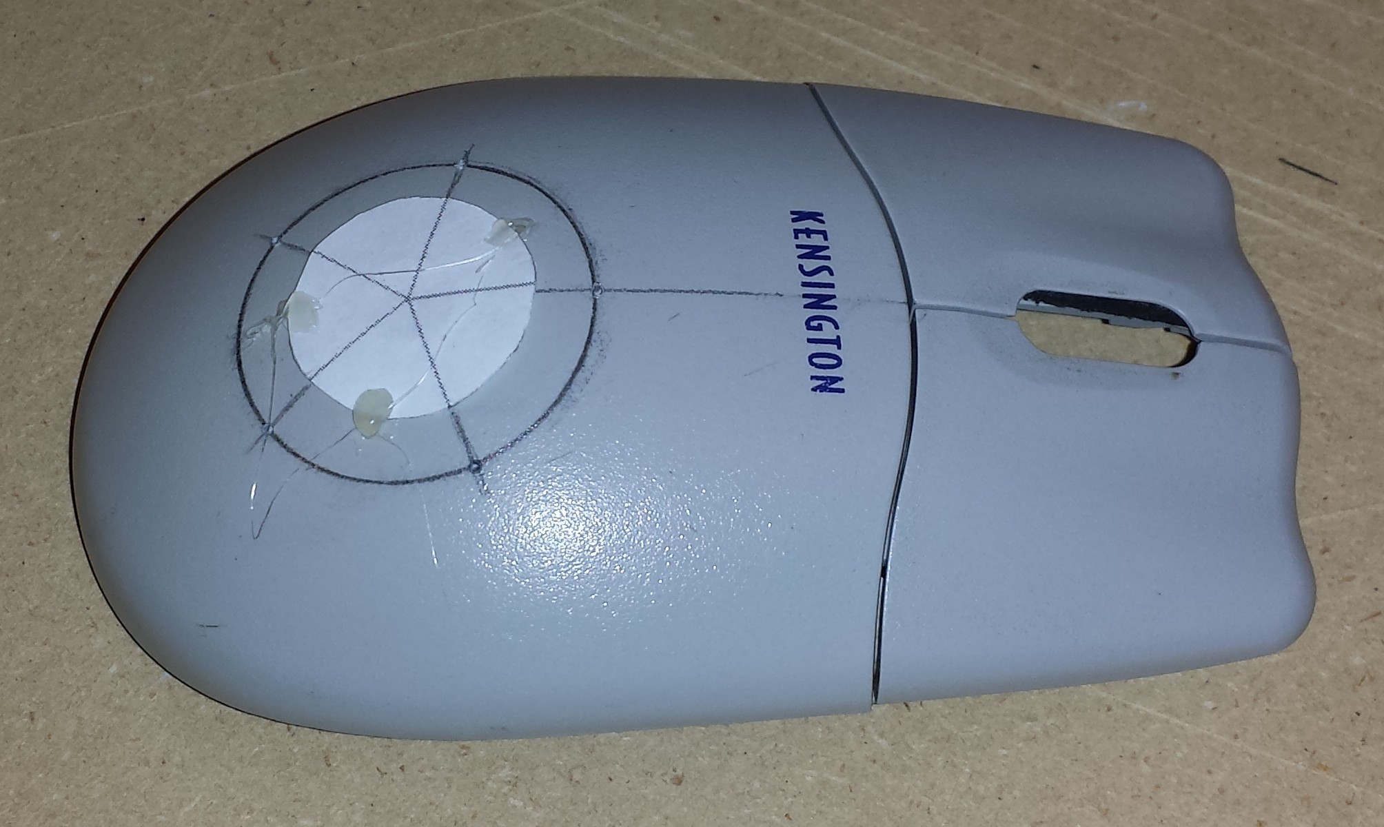 In order to space the 5 LEDs evenly, I created a quick 2D drawing in FreeCAD of a circle sliced every 72 degrees. I drew on a circle using a circle template of 1 1/4". I printed the drawing out undersized and extrapolated where to place the LEDs. I marked the center of the circle and the intersections with a punch to aid in drilling.
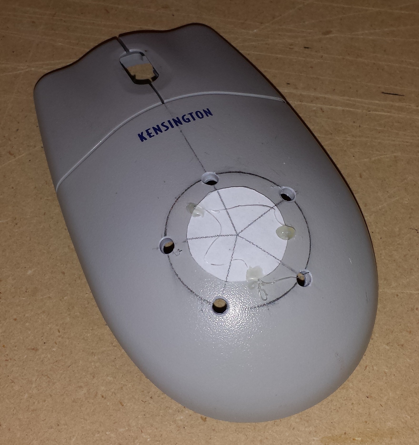 Due to the non-flat nature of this mouse, I opted to drill this using a hand drill rather than my drill press. It probably doesn't matter too much, but it seemed to work out well. I then drilled out the larger hole for the CDS sensor with a short length of heat shrink tubing to block ambient light.
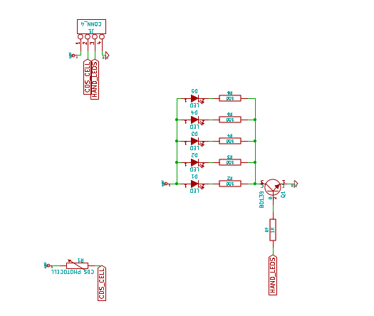
 The LEDs were glued in place. I made all of the LEDs anodes face inwards since they are all connected together. (Yes that is a roll of duct tape holding the mouse so I can work on it.)
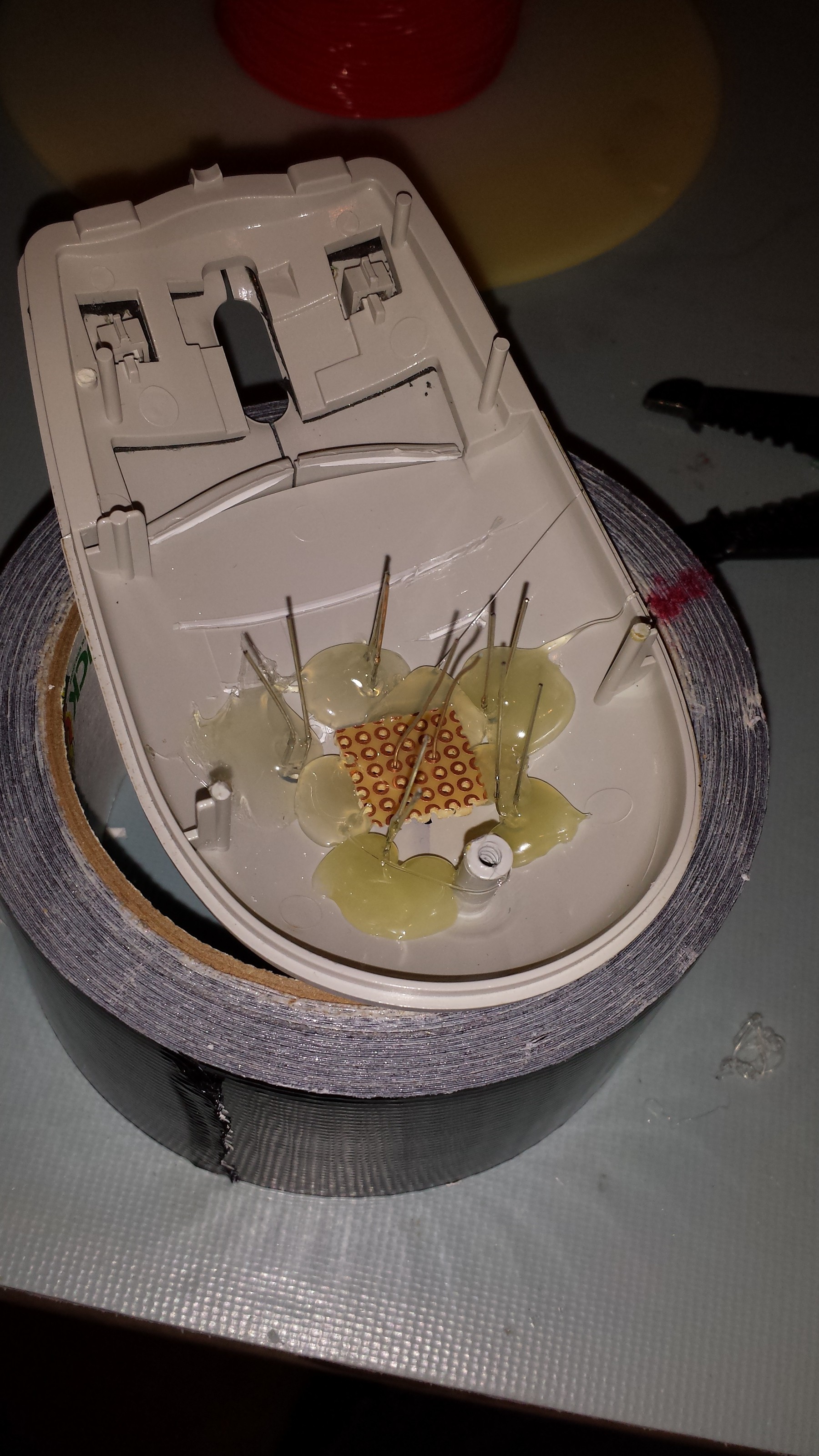 I'm using a small piece of protoboard to help hold the CDS cell in place. I then built up hot glue around the protoboard.
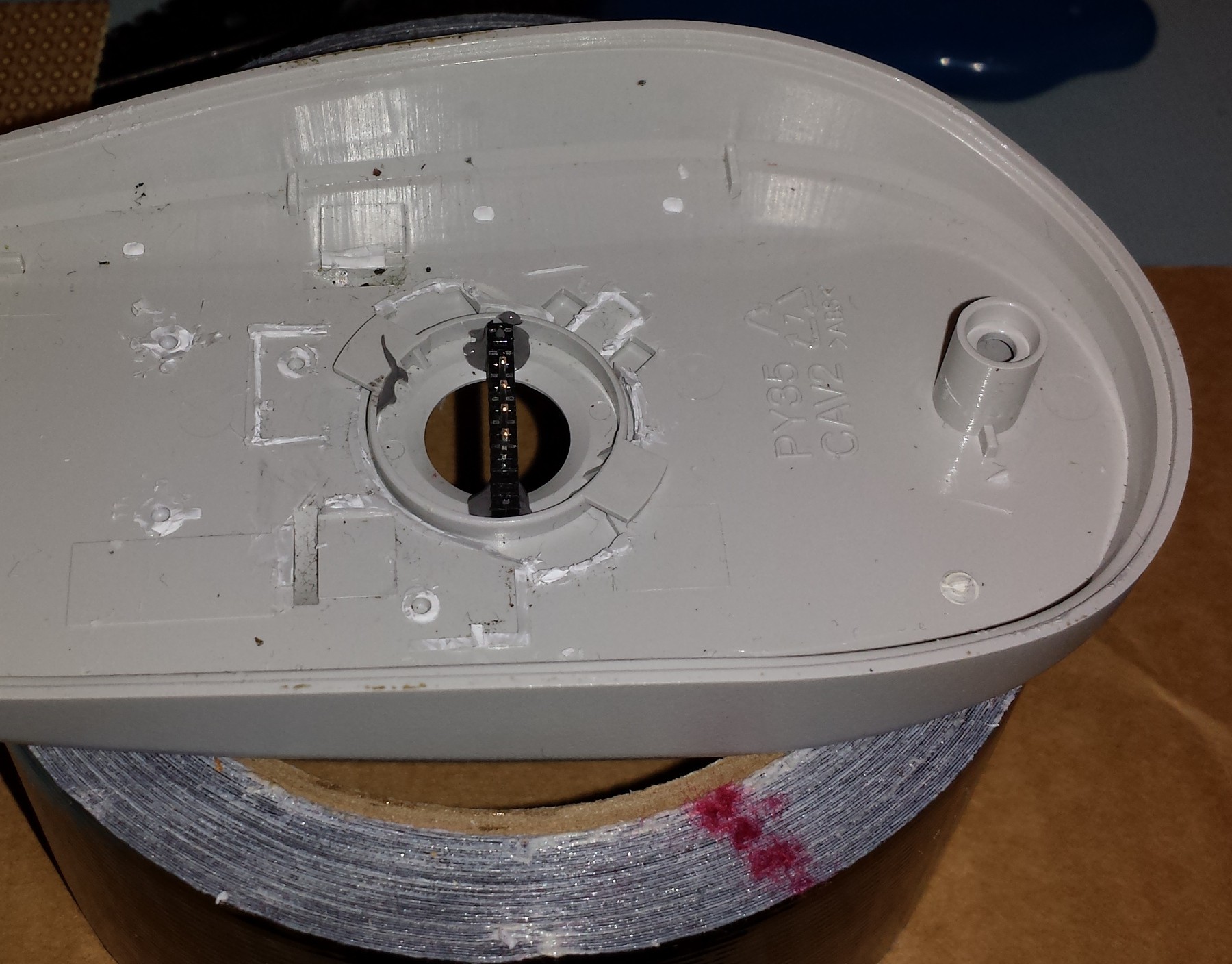 Here is the first of two headers glued in to the bottom of the mouse. The box will have mating connectors embedded in the bottom that will interface the Hell Mouse to the rest of the electronics.
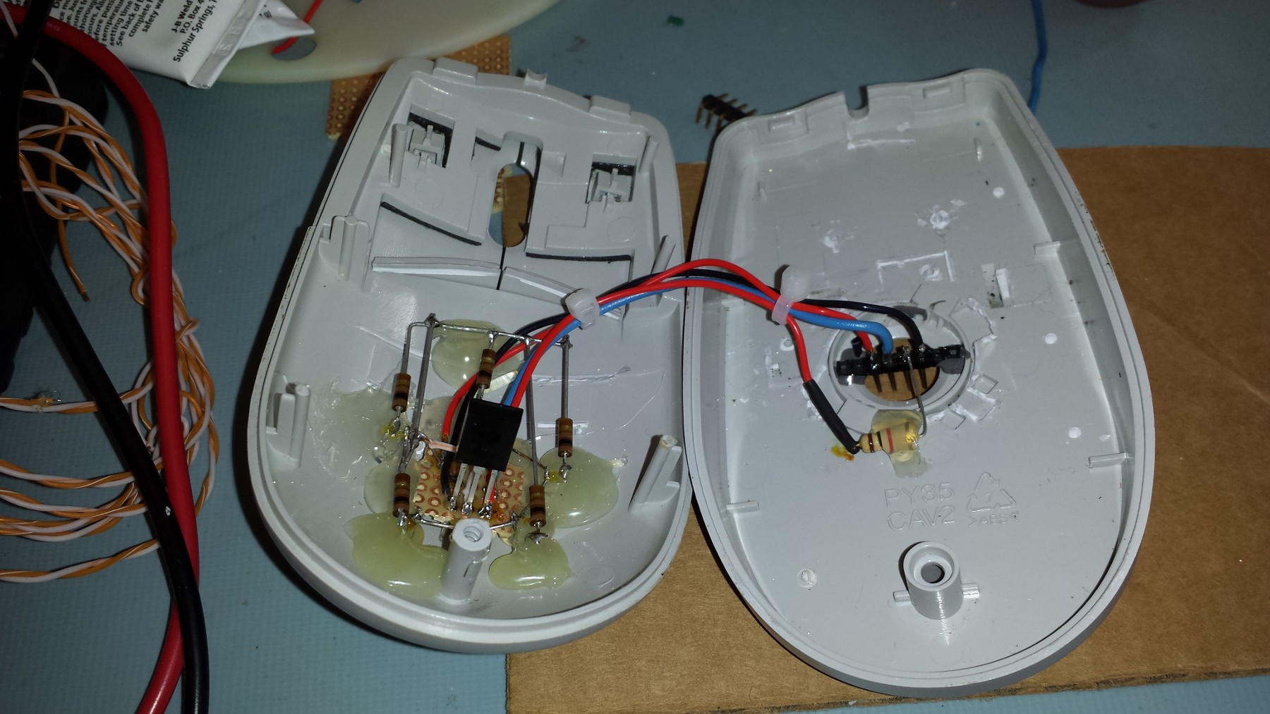 I wired this clam shell style so it could be easily opened and accessed if needed.
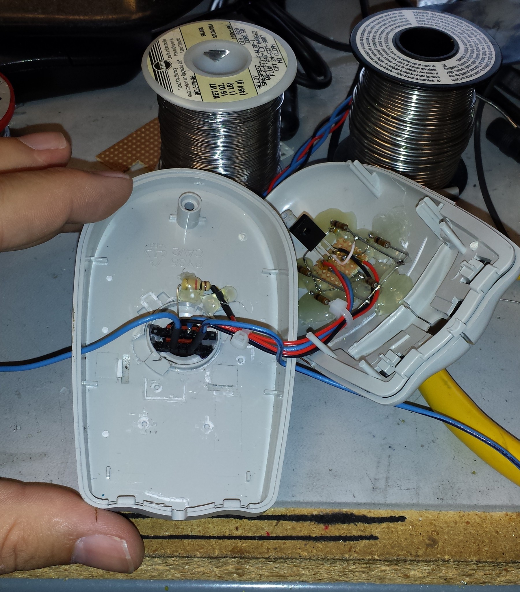 The second header for the high voltage electrodes is shown above with the blue wires. A normal 0.1" header was used. The middle pin was pulled out to give the high voltage wires some distance from one another. I have a video (which I will upload later) of this sensor being tested and it seems to work great!
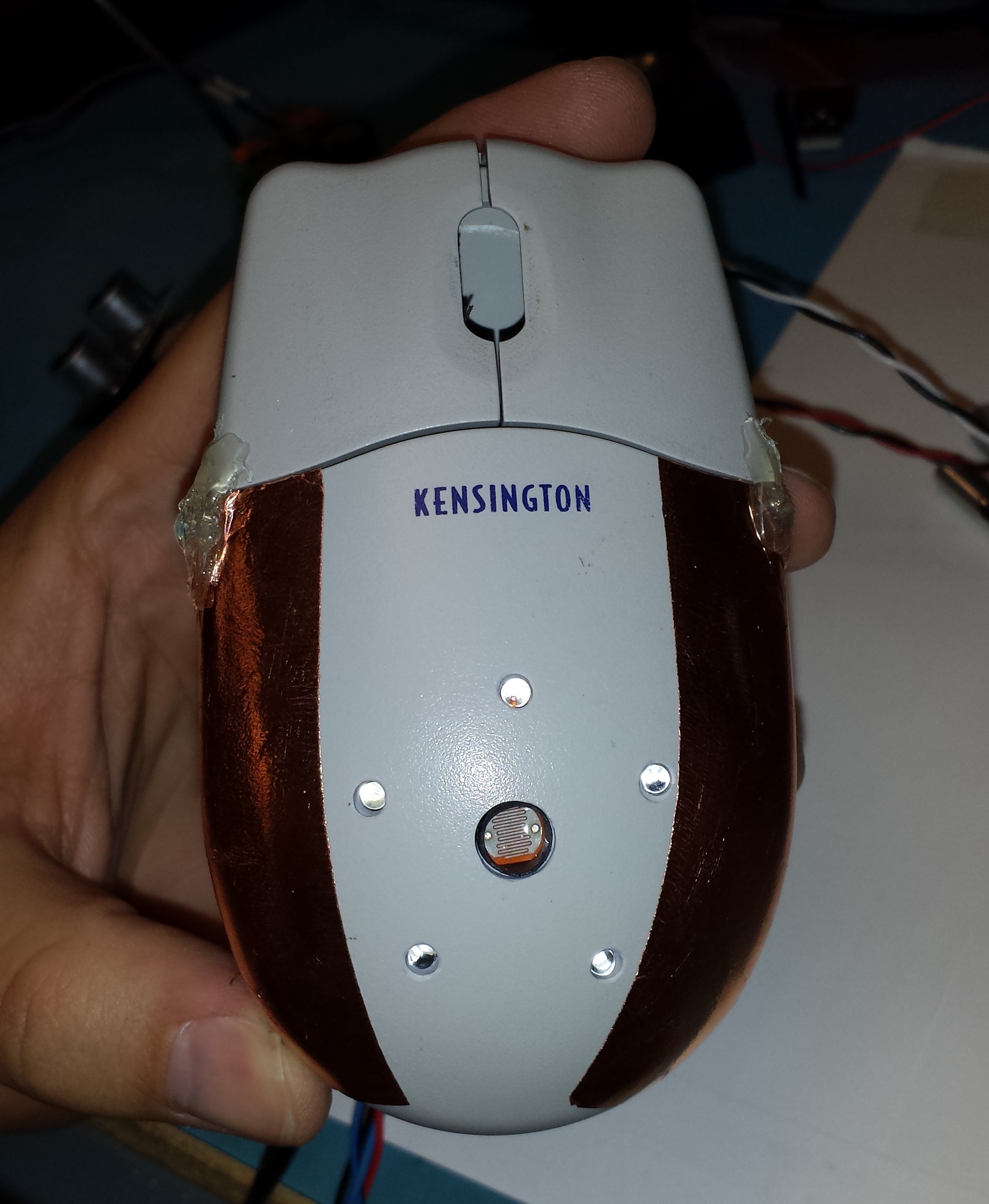 [x3n0x] applied some strips of adhesive backed copper foil to the Hell Mouse. I ran wires from the high voltage header to each side and tacked it on with solder. Unfortunately the stupid copper foil started peeling off and threatening to rip, so I had to tack it down with a ugly glob of hot glue. Other than the hot glue globs, this thing is looking pretty good so far!
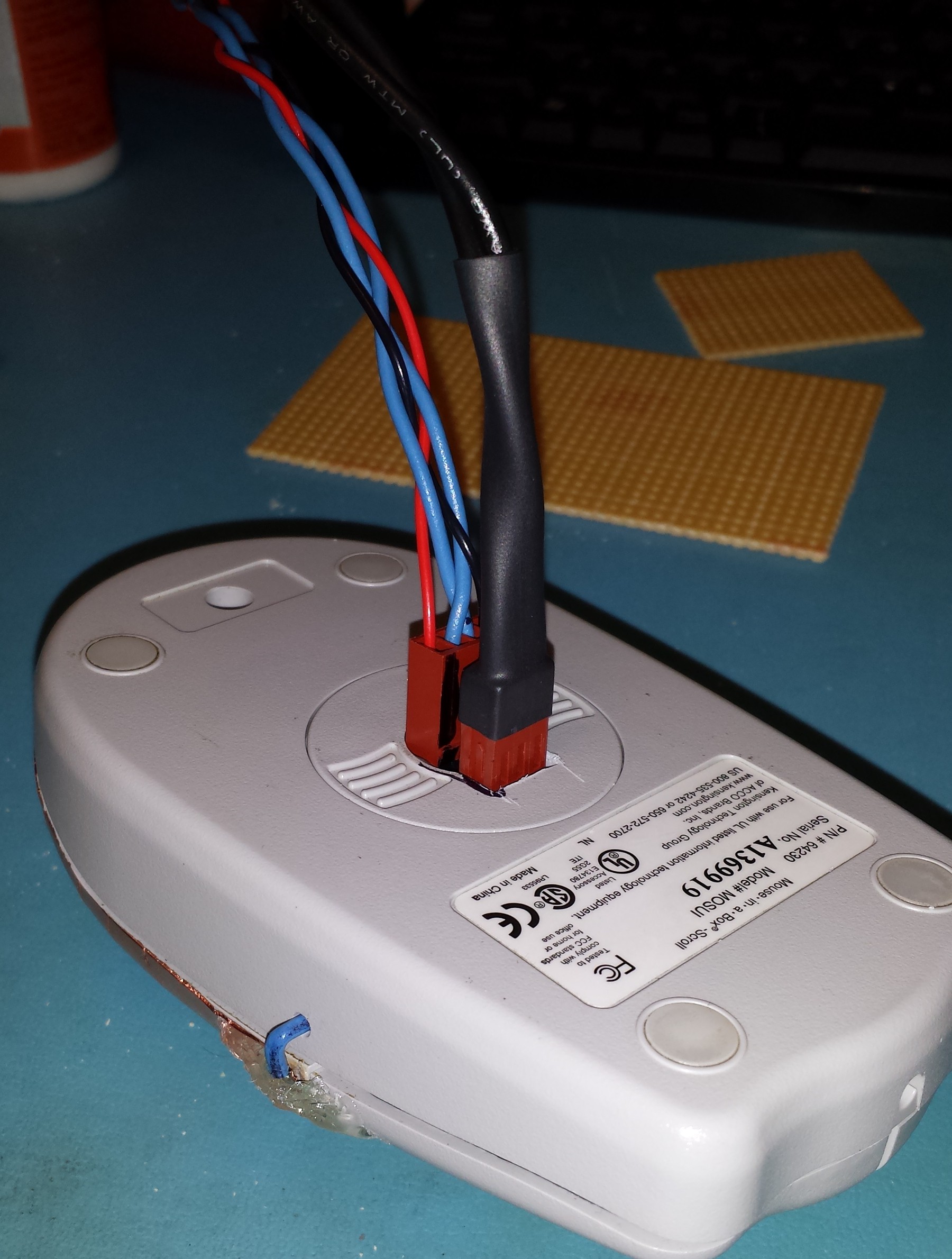 Trying out the fit of the connectors to the headers. I had to cut out a chunk of plastic so the high voltage connector could get fully seated to the header. This wire harness will be integrated into the bottom of the pain box.
 I added 2 narrow strips of hook and loop to the Hell Mouse to help hold it down securely, yet remain removable. I was afraid the hook and loop strips would tear off the foam core, but the few test disconnections showed it was working perfectly.
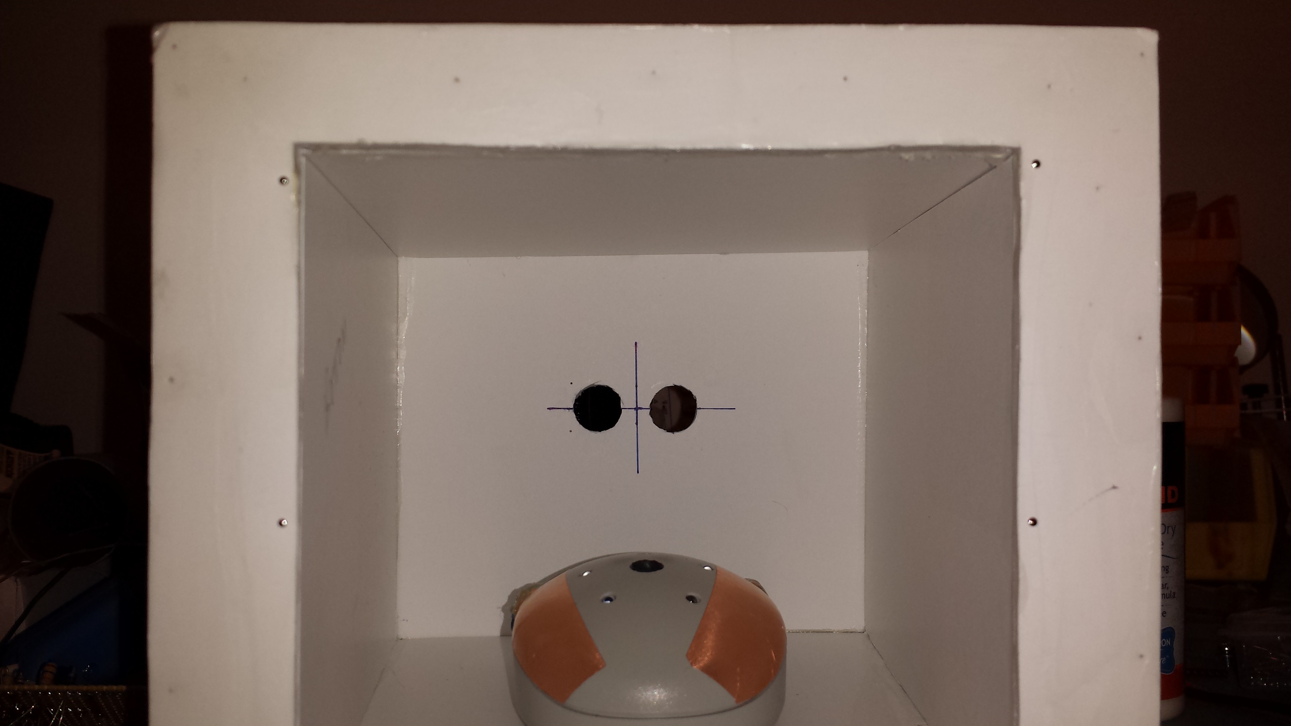 Here is the little beast installed in the box, ready to assist the Reverend Mother in testing for animals.
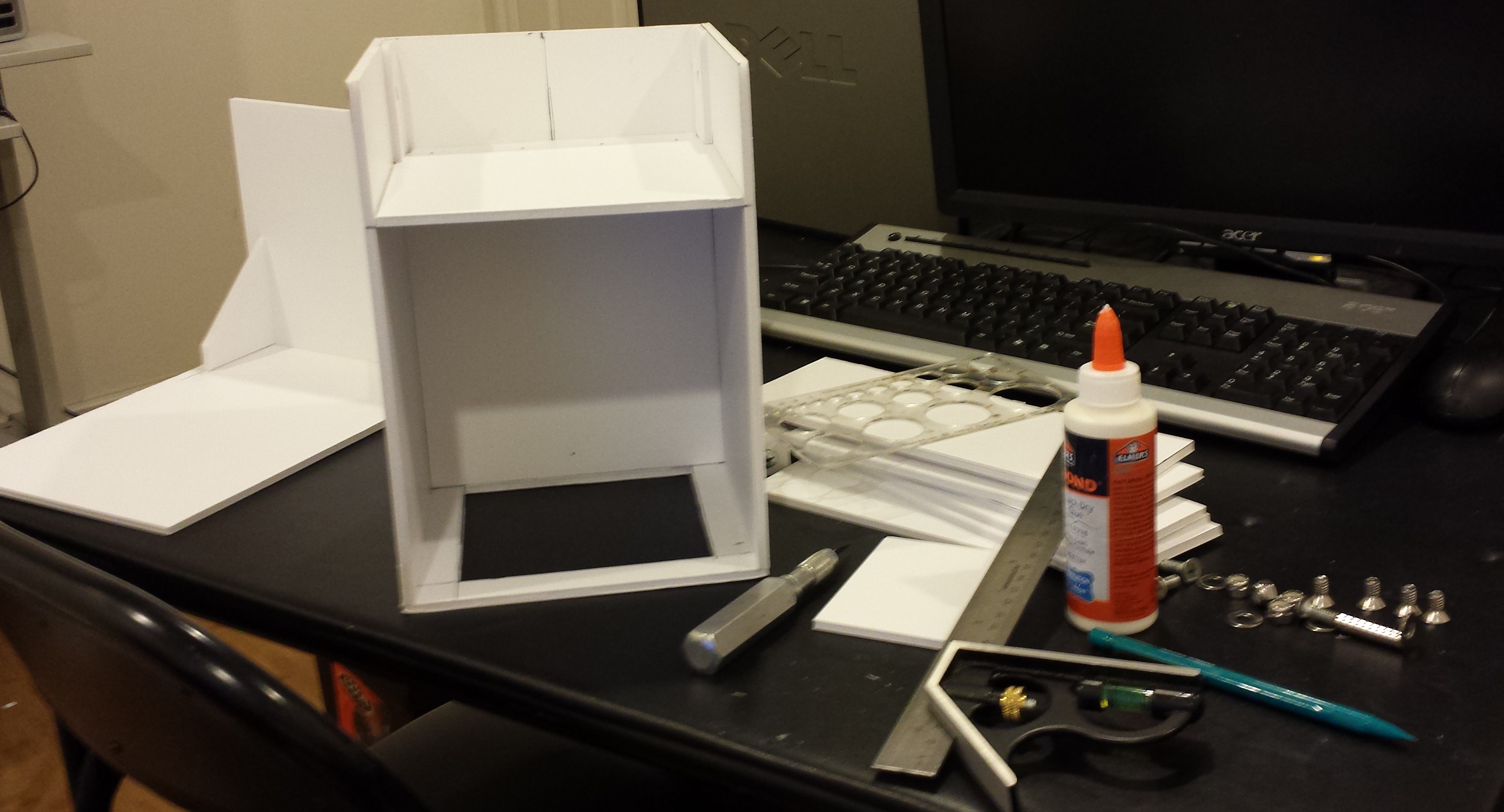 The false back can be seen here which will separate the hand part from the electronics guts of the device. The above photo also shows the cover which includes the top and back of the box. The idea is to make the cover fairly easy to remove in order to have easy access to the electronics.
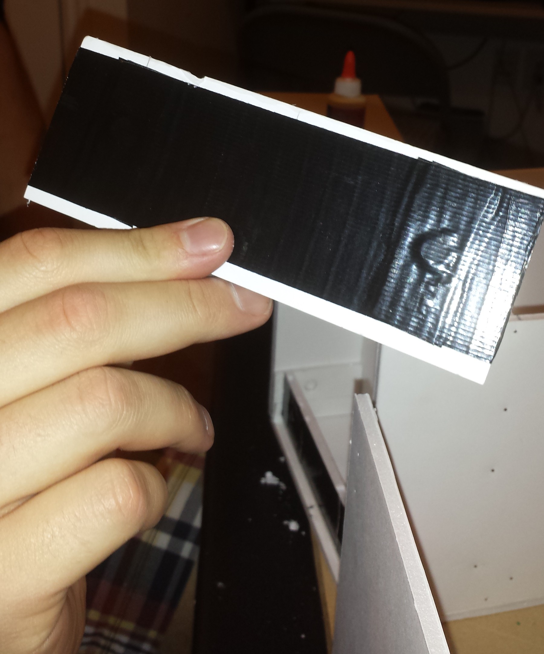
 This photo shows the hand chamber boxed in with more foam core. Notice the side walls are narrower in the front and flare out in back. Also visible are the cutouts for the ultra-sonic range sensor in the back, and the hand rest. The hand rest will be covered in more depth in a separate log.
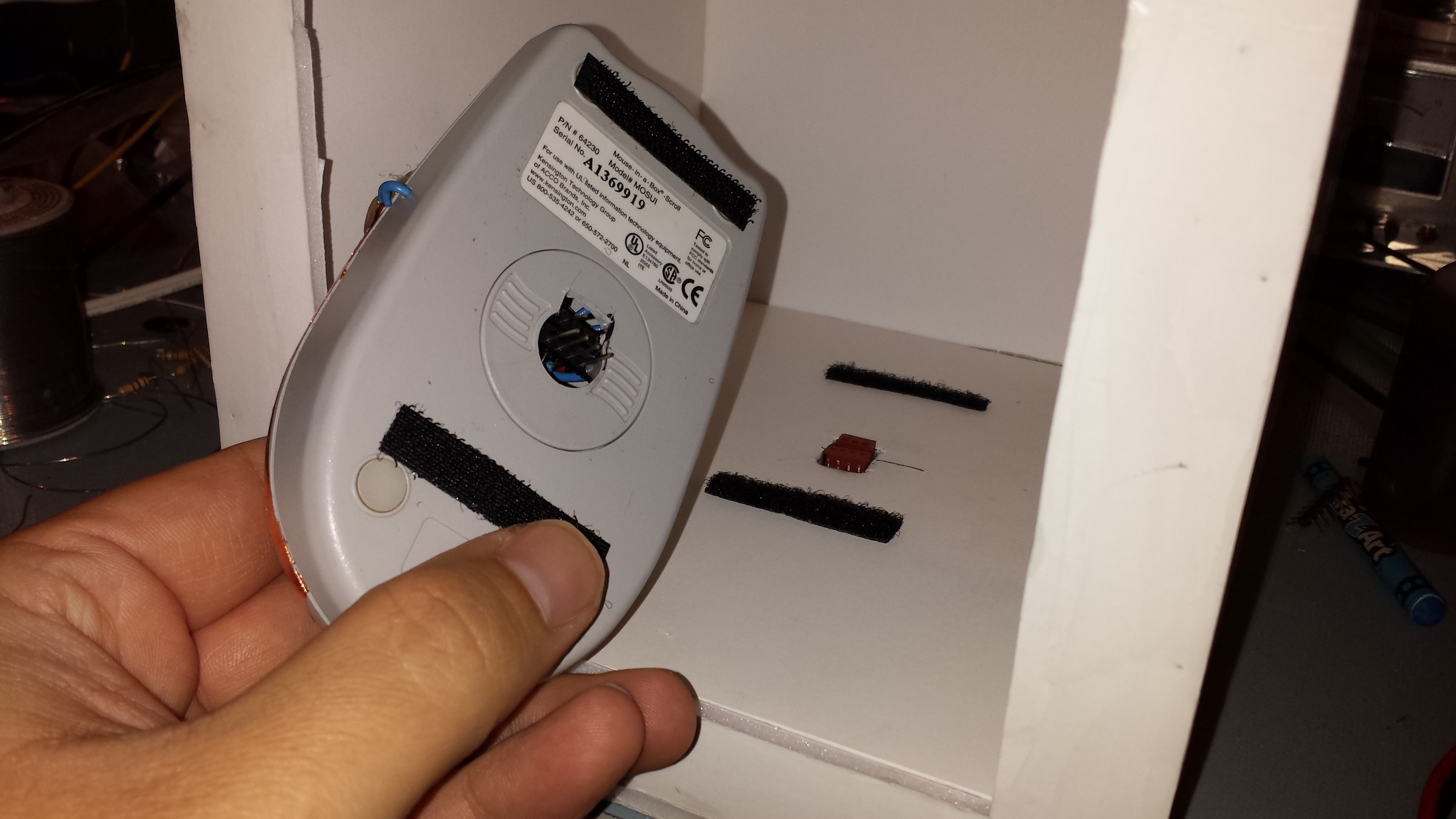 I made the hand rest removable using hook and loop strips and a couple of connectors. It may not be clear from the picture, but there are two headers glued across the opening where the ball used to go in the mouse. One is for the high voltage electrodes and the other is for the hand sensor connections. There are two mating connectors on the bottom of the box which bring out the high voltage wires and the hand sensor wires to the back. These connectors were glued in the cutout on the bottom after the hand rest was seated on them to get the height right. Again, more details on the "pain mouse" will follow in a separate post.