 x3n0x
x3n0x-
1Step 1
PLEASE NOTE: Before you dive right in and assemble your Wave shield, there are a few things you will need to take note of: Make sure that you use the 'Stacking headers' on your wave shield. It will be in the middle of the stack so that we can put the proto-shield on the top. You will also wire the connections on the wave shield to the Arduino pins a bit differently! More information about the Arduino stack up will be given later. Now, on to the Power supply:
Acquire the necessary parts to build the power supply from the following sources: Some old computer power supplies(at least 2), and old skool CRT monitors or TV's. You need to look for and carefully remove the following kinds of parts from your computer power supply:
![]()
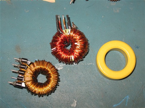
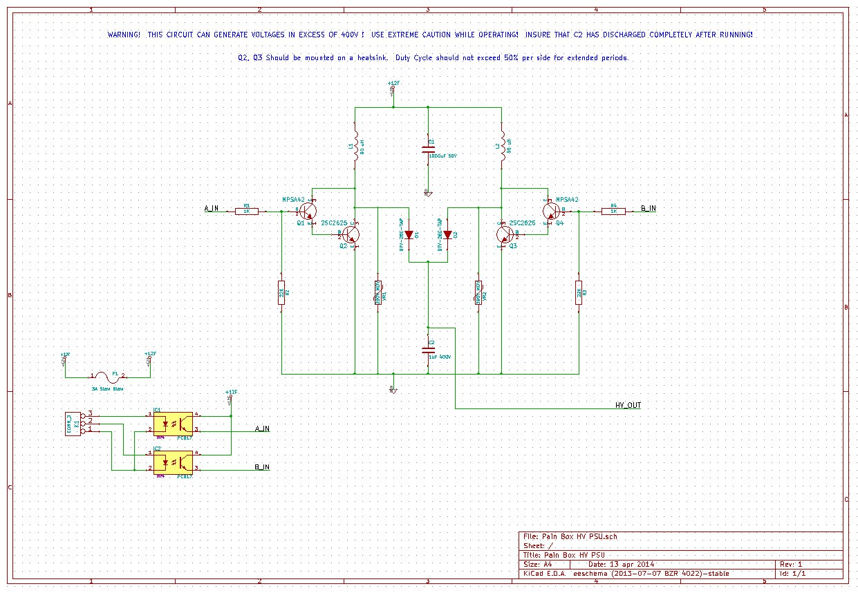
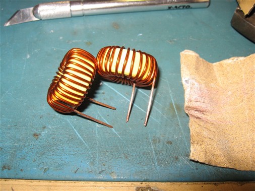
You should find at least one of these inductors in each donor computer supply, near all the output filter caps and the wire bundle that solders to the board. Remove it, and strip off the magnet wire to get a core that looks like the yellow doughnut above. You will need two of these cores for this project. There are tons of other useful things in there too, so don't throw them out yet...
Then, remove these from the high voltage side of the power supply, usually on the large heat-sink by the huge input caps:
![]()
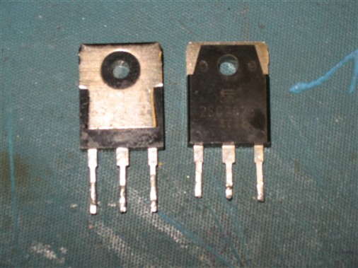
I find these in just about every make and model of computer power supply I take apart. They have the part number 2SC2625. They are 10A, 400V NPN power transistors. We will be using these for the main switching element in our new HV PSU.
Next attack your CRT. Be sure to discharge the CRT and the board attached to it before attempting any work inside the monitor or TV! The voltage inside can easily kill you! Don't say I didn't warn you! Remove the following parts from your donor CRT board:
![]()
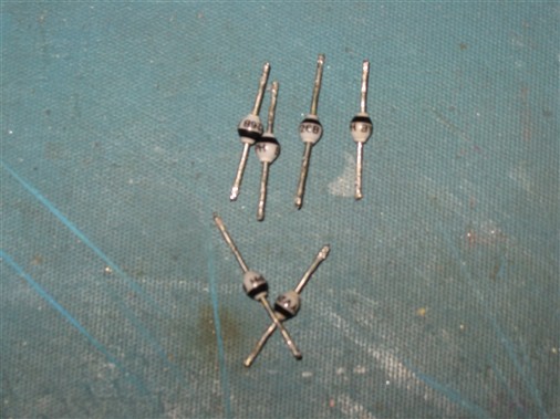
You need two identical ones with the same part numbers. I used some BYV26B parts in my power supply. Save these diodes. They are useful for high voltage experiments! They can usually be found nestled around all over the board, usually next to FETS and Transformers. Also, you know those big Blue, red, and orange things all over the board that kinda look like candies? They are high voltage film capacitors! Rescue as many of them as you can (carefully! The encapsulation likes to crack around the pins if you are not carefull!). You will need two identical ones rated to at least 400V for this project. Hopefully, you can find some that will total 1uF or so when hooked in parallel.
-
2Step 2
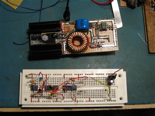
Now that you have gotten some of the parts, and hopefully stocked your parts bins and caused some carnage in the process, we are ready to proceed. This is the end goal of this hullabaloo:
![]()
You will wind two large inductors using the cores you salvaged earlier, use the diodes you rescued, and also the transistors. Sadly, you may have to buy some stuff from digikey or mouser, but thats the way it goes sometimes. Unfortunately, its pretty hard to scrounge everything, but for the most part, you can usually rescue a lot of stuff from discarded electronics.
Here is a schematic that you can hopefully use to build this part of the device. (All the source files will be included as a zip after project completion)
![click to embiggen]()
Before I get flamed, I realize that this circuit is FAR from optimal, and probably likely to make smoke at some point in its life, but this is a hack, right? Besides, it seems to work pretty good for a hack, and as long as it doesn't grenade immediately when we use it it should suffice for our purposes.
While theory is way beyond the scope of this project, briefly, we will turn each inductor on for some amount of time to store energy, and then quickly shut it off. This makes a high voltage spike as the magnetic field collapses, which passes through the diodes into the high voltage capacitor, giving us what we want; High voltage DC! If we pulse each half in turn, and control the duty cycle, we should have a pretty good degree of control over what comes out of the output. Note the Opto-isolators! This helps isolate this dangerous circuit and its associated bad behavior from the sensitive Arduino and wave shield. The particular type of Opto-Isolater in the circuit is not too critical, and the type called out in the circuit can be had on ebay by the dozen for very little cash.
Next, on to winding the inductors!
-
3Step 3
![]()
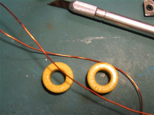
Winding the inductors is easier than you might think! I used about 4 feet of 18GA Magnet wire to wind the inductors for this particular power supply. Each inductor has ~30 turns on it for an inductance of about 90uH. If you don't have magnet wire, 24 gauge stranded wire will work ok in this instance, as we are not going to be running very high frequency. The easiest thing to do is to cut off a suitable length of magnet wire, and just start winding them, being careful not to let the magnet wire kink, and making sure you get the turns snug around the core and with relatively even spacing. The most difficult part is starting the first few turns. Start by leaving about an inch long tail of wire, and winding the wire around through the middle of the core. after a few turns, the wire will kind of hold itself on, and it will be easier to tighten the turns as you go. Here is a picture of one of the inductors being wound:
![]()
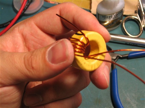
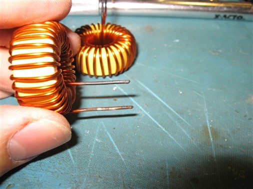
You need two of these, identical to one another, one for each half of the power supply. Take your time and be careful, or you will end up with a mess of wire that will not work well, and will probably need to be thrown away. After you have wound them, trim the tails to about 1-1.5 inches, and remove the enamel (if you used magnet wire) from the wire, almost all the way to the core, leaving about 1/8". If you used stranded wire, then, I cant help you... Well, ok, just leave a manageable amount on there and strip it down and tin to where you need it when you put it into the circuit. An easy way to remove the enamel from magnet wire is to heat the wire with a lighter until it flames up and turns black. Then, using some fine sandpaper (200 - 400 grit) remove the charred enamel from the wire until you see the shiny copper underneath.
![]()
If you do not do this, you will not be able to make an electrical connection to the wire, and the inductor will not work properly. After you have removed the enamel, apply some paste flux to the copper and tin the exposed copper with your soldering iron. You should get a smooth coating of solder on the exposed copper, allowing you to make a good electrical connection to the inductor. If you have access to one, it is a good idea to check the inductor with an LCR meter to see that the value is right. The value is not terribly critical, but should be around 85-90uH.
![]()
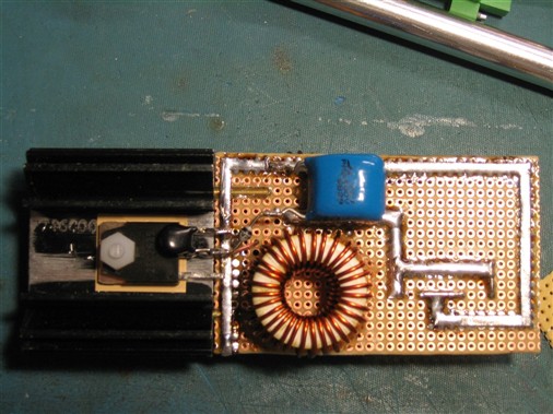
Once you have these inductors, simply build the HV PSU per the schematic above. The only part you will not be able to get for the PSU from scrounging will probably be the MOV's across the emitter and collector of Q2 and Q3. These can be gotten from digikey for a resonable price. I used part number ERZ-V07D361 because I had some left over from another project, but anything similar will do, as long as the breakdown voltage is less than 400V and greater than 300V. If you do not include this part, you run the risk of popping Q2 or Q3 because of over voltage. How you construct the circuit is up to you, but be sure you make the connections between C1 and the inductors large, as well as the connections between the other terminal of the inductors and the collector of Q2 and Q3 also large. be sure the the connection from both the emitters of Q2 and Q3 are large as well. This is necessary because there are heavy currents that flow in these paths during switching, and we can help a bit with the dismal efficiency of this thing by keeping them large, low inductance, and low resistance. Note the wide fat paths I used to connect those parts of the circuit below:
![]()
A good way to do this, instead of blobbing up solder, is to use some of your de-soldering braid as the connecting wire. It is fat and has a lot of copper, allowing a low resistance, low inductance path for the large currents to flow. Once you have built the power supply, and double checked all the connections, you are ready to move on to the pulse distribution and control circuit. If you want, this power supply can be tested using a 555 and some logic gates or even a micro-controller to generate a 25-30% duty cycle pulse that triggers each side every other time, or, in other words, you drive A for one pulse, and B for the next pulse and back and forth between the two sides. A frequency of about 16 Khz(8 khz per side) seems to work well.
A high voltage will develop across C2, and you can measure it carefully with a multimeter to see what it reaches. It should be about 150-200V pretty easily, more is the duty cycle is larger. Be careful, as you can receive a nasty shock from C2 during, and even several minutes after the unit is powered off! If you have ever wondered what it felt like to be zapped by a photo flash unit (don't ask!), well, this will give you a taste, but doesn't have as much energy! IT WILL HURT! I PROMISE! Just trust me and be careful mmkay?
In the next phase, we will cover some basic theory and construction of the pulse divider circuit, and the touch-release sensor circuitry. Stay tuned, give skulls, follow and enjoy! Thanks!
-
4Step 4
Now that the PSU is done, Arguably the most difficult part, the rest is pretty easy. There are two major components that need to be built now: The control circuit for the HV psu, and the Hand sensor.
These are the last two critical custom parts that need to be created. There are a few other parts to the full device, these include the Wave Shield, the Proto Shield, and the Arduino itself. We will talk about these soon, but for now, let us focus on the hand sensor, and the control circuit.
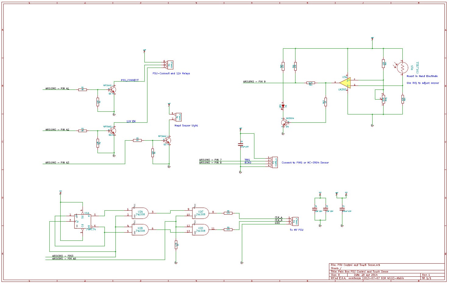
Here is the schematic for the control circuit:
![]()
Well, it has the control Circuit, and the hand sensor circuit on it too. This entire thing was built on the proto shield in our case. It bearly fit! It is really up to you how this circuit gets implemented, but it provides the interface between the Arduino, and the rest of the project. Micro-controllers aren't very good for turning on relays and stuff, so transistors are included as well as some pulse control stuff for the HV psu.
The PSU control portion of this circuit is the part at the bottom, consisting of a 7474 'D flip-flop', and a 7408 'AND' gate. The circuit's purpose is to steer the PWM pulse train from the Arduino into two separate outputs, one for each half of the HV PSU. This prevents applying more than 50% duty cycle to either side, which could result in smoke or grenades. The Flip-Flop toggles its outputs every pulse, and the 'AND' gates direct the pulse from the Arduino into another 'AND' gate, that acts as an enable, so that we can turn the PSU off completely, without stopping the pulses from the Arduino.
The op amp circuit on the top right is used as the 'Hand' sensor. Technically, it is a darkness sensor, but the way it will be mounted in our case, it will be used to detect the test subjects hand on the electrodes inside the box. The circuit simply looks at the voltage from two voltage dividers, one made by a 10K resistor and a 10K potentiometer, and the other made by the CDS cell, or photoresistor, and another 10K resistor. The photoresistor increases its resistance, the darker it gets. This causes the voltage applied to pin 2 of the Op amp, in this case an LM393, to drop as the darkness increases. The voltage at pin3 is relatively constant, once RV1 is set, and when the voltage on pin 2 gets lower than the voltage on pin3, the output of the Op-Amp goes high, indicating a 'Hand'. The LED and on the output of the Op-Amp is there to help set RV1 once the unit is installed how is should be.
The rest of the transistors are used to turn on relays, or to turn on LEDS in the case of the 'Hand Sensor Light' More details on how the hand sensor works will be given later during the final assembly of the box.
For now the circuit as shown above should be assembled, and all the connections verified. To test it, upload the sketch (to be uploaded) TestControl and follow the instructions in the serial monitor. You will need an oscilloscope to test the PWM outputs, as well as a CDS cell, and the HC-SR04 sensor. You can hook some LEDS to the transistor outputs, hooking ground to the collectors of Q1, Q2, Q3, to test them, following the prompts on the serial monitor.
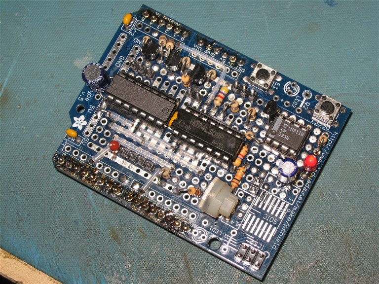
Here is a picture of the PROTO shield with all the stuff on it:
![]()
At this point, pretty much the only thing left, is to assemble everything with the hand electrodes and sensor, speaker, and the rest of the electronics into the facsimile of the 'Pain Box' that you create, hook it all up, and load the sketch! Almost there!
-
5Step 5
In this step, how the Arduino shield stack gets assembled, and how to wire your wave shield will be discussed. If you remember the note from the top in step 1, You hopefully used stacking headers to build your wave shield. If you didn't, or already had one built, you'll need to install those stacking headers in order to use it for this project.
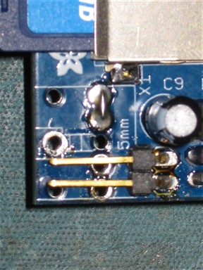
To make the Arduino stack, you need to assemble your wave shield with a couple minor modifications: First, you'll need to use the stacking headers as mentioned above. Second, you need to remove, or not install the headphone jack that came with it, and install a jumper in two of the pins as shown in this photo:
![]()
Note the small jumper on the left two holes. This connects the output of the Wave shield to the holes for the header, which you can see in place of the headphone jack. This right angle header is where we will be hooking the amplifier up to get the sound out of the wave shield. Since the Wave shield will be in the middle of the stack, it is easier to use this right angle header versus a standard one.
Optionally, if you choose not to modify your wave shield, you can hook up to your amplifier using a headphone cable and the jack. This actually makes life easier if you already have a small battery powered amplifier to use for this project. In our case, the amplifier was not equipped with a nice plug, so we just used the header to connect to some wires and a small plug to make the connection. The amplifier can be any small device that is suitable for use in this application. By suitable, I mean it does not need to be more than a watt or two, should be simple to connect, and simple to power. You may even be able to get away without one, as you can simply connect the speaker to the output of the wave shield. This may be loud enough for your purposes. In our case, we wanted it nice and loud, as our gatherings tend to get a bit noisy at times, hence, the amplifier!
![]()
In this photo of the wave shield, take note of the connections made to the Arduino pins. They DO NOT follow the instructions given on Adafruit's tutorial for Wave Shield assembly. The main reason for this is that we need Arduino PIN3 for high speed hardware PWM to drive the power supply, and this is used by the Wave Shield in the default configuration. Make the special connections as follows:
Wave Shield LCS -> Arduino PIN6, NOT Pin 2
Wave Shield CLK -> Arduino PIN2, NOT Pin 3
All the other connections can remain the same. Please note that this means the pin definitions in the Wave HC Library will need to be adjusted to reflect the change. This is discussed in the Sketch for the Pain Box which will be available for download later on.
Assuming you built the control and sensor circuits on the Proto shield, the stack up goes as follows:
Bottom - > Arduino UNO
Middle -> Modified Wave Shield
Top -> Custom Proto Shield
If you didn't use a proto shield to make the control and sensor circuits, you are on your own with the construction from this point on with reguards to your Arduino set up.
As a side note, all of the IO pins are pretty flexible, excepting anything used by the Wave Shield (Hardware SPI pins are notable), PIN 3, and PINS 0, and 1. Since we are not using the analog inputs, those were used for digital IO in this project. All the pins are defined at the beginning of the sketch. as well as their purpose, so they can be customized to your needs. The notable exceptions to this are the pin definitions for the WAVEHC library. These are not immediately accessible from the sketch, and the header file WavePinDefs.h in the library folder will need to be changed to accommodate the hardware PWM. Details o nhow to do this can be found in the sketch that will be uploaded at the conclusion of this project. This completes all the stuff reguarding the Arduino Stack up! On to wiring the thing!
-
6Step 6
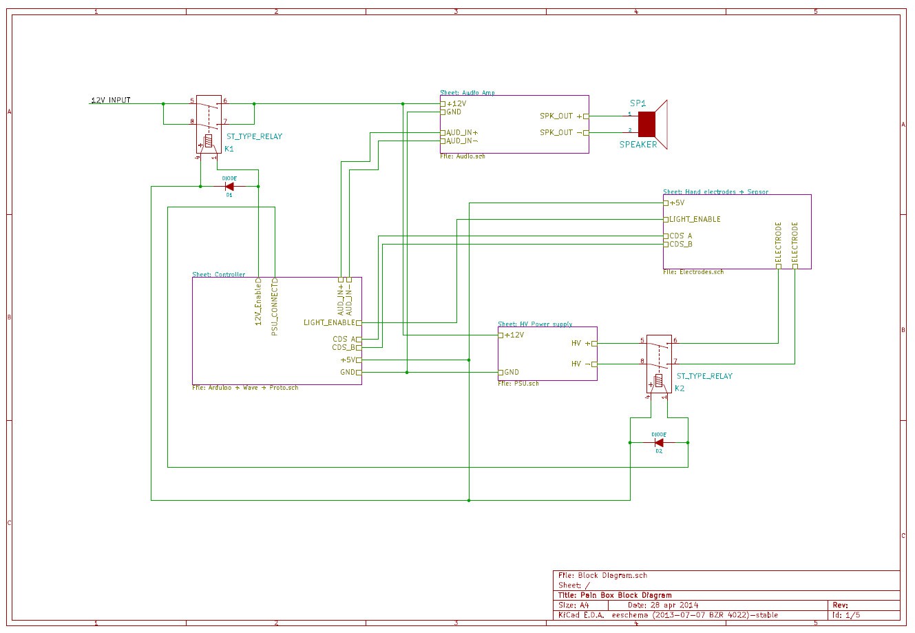
First, here is the block diagram:
![]()
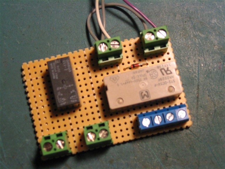
You'll note that there are two relays in this circuit. These are used to connect the HV output to the hand electrode, and turn on the 12V supply to the Amp and HV power supply. You can spider wire them in and just stick them into the box, but we decided to make a small board that included all the connections and both relays with some terminals to make the wiring a bit easier:
![]()
This little board includes both relays to make the necessary connections. Both are 5V coils.
The tan colored one (Panasonic ST2-DC5V-F) is rated for high voltage, and has 2 Single pole single throw contacts. It is used to connect the HV output to the hand electrode, which can be seen in the box fab pictures.
The smaller black one (Omron G5V-2) is rated for 2A per side and hooking both halves together in parallel gives us some headroom for the 12V current needs. I didn't have another Panasonic one, which would have been better, so the Omron one was used instead. Just goes to show that things are pretty flexible, and you really can use what you have in the junk box to get this thing going!
The two green terminals by the black relay are the Positive and GND connections for the 12V supply. The relay only switches the positive side. The blue terminal is divided in two basically, with the two left terminals used for the hand electrode, and the right two terminals for the HV output.
The other green terminal blocks on the 'top' of the board are simply the inputs to control the coils of the relays, connected to the Arduino outputs. The diodes for the flyback from the relay coils are right on this board, and connected as shown in the block diagram.
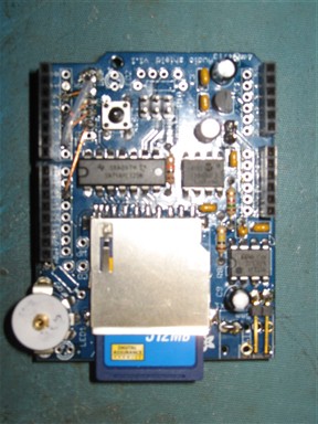
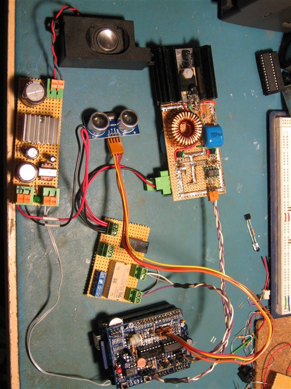
Here is a picture of the whole setup on the bench, during coding, all connected except the actual hand electrode, and the actual hand sensor. (They were being mounted in the box at the time this photo was taken)
These two items (hand sensor and electrodes) will be described in detail during final assembly.
![]()
This whole setup can be powered by one single 12V supply, using the Arduino's built in external voltage input and 5V regulator, or the Arduino and control circuitry can be powered from a 9V for example, and the rest (amp and HV psu) from a large LI-Po or lead acid cell for portable operation. With some optimization, the 12V power can be switched by the Arduino to provide very low power consumption when the system is not actively running or playing sounds. This is planned as a future upgrade to the code\hardware at a later date...
As it now stands, this whole setup works very well with the basic first revision of the sketch. It hurts like hell, and now just needs to be fine tuned for proper sensor behavior after mounting into the box during final assembly! Its actually kind of cool to here the sound-clips playing on que with each phase of operation! Next stop, Final Assembly!
-
7Step 7
To get a good idea how we made the electrodes, you can read the project update entitled "The Hand Thingie". If you want to use the same sensing set up we used, this worked well. Any sort of Object that is fairly ergonomic and can have the electrodes and the sensor set up mounted inside will work to perform this function.
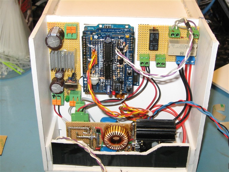
How you cram all the stuff into your box is really up to you, and it really is dependent on what your final boards, i.e, the power supply, amplifier, relay etc all end up looking like. This is a picture of what the inside of ours looked like after we got it all crammed in there:
![]()
The speaker is the only object not shown here, and we ended up mounting it on the upper left hand side of the enclosure. The Ultrasonic sensor is mounted just under the bottom of the Arduino, and you can just see the edge of the board sticking out on the bottom right edge of the Arduino Stackup. Some of the wires are also not present. It is a really good idea to use terminal blocks and plugs to make this step a lot easier.
After we did some open dry runs and tweaked the code a bit, we made the video posted in the final project update. There is a bit more description in the video describing some of the other things we did to help get everything together and working. Again, I also highly recommend you read 'The Hand Thingy' update to get a good idea on how the hand sensor is mounted and the theory behind it...
One thing to note is that is is a heck of a lot easier to connect to the Arduino before you mount it this way. The USB plug is on the bottom, facing downward! We will probably change this when we revisit the box construction, but for now this worked to prove out the idea.
No go forth, and make more pain boxen, so that we may rid the world of 'Animals'! If you liked this, please don't hesitate to give us a skull... Also, leave comments, tell us what you think!
Discussions
Become a Hackaday.io Member
Create an account to leave a comment. Already have an account? Log In.