Software: https://github.com/aanon4/borgcube-rov
To make the experience fit your profile, pick a username and tell us what interests you.
We found and based on your interests.
Software: https://github.com/aanon4/borgcube-rov
T100-THRUSTER-R1 - Main.stlStandard Tesselated Geometry - 9.66 MB - 02/12/2017 at 21:04 |
|
|
T100-THRUSTER-R1 - Support.stlStandard Tesselated Geometry - 4.26 MB - 02/12/2017 at 21:05 |
|
|
T100-THRUSTER-R1 - Back.stlStandard Tesselated Geometry - 2.83 MB - 02/12/2017 at 21:03 |
|
|
T100-THRUSTER-R1 - Prop.stlStandard Tesselated Geometry - 1.45 MB - 02/12/2017 at 21:03 |
|
|
T100-THRUSTER-R1 - Prop (Rev).stlStandard Tesselated Geometry - 1.45 MB - 02/12/2017 at 21:04 |
|

Just updates the project with the STL for all the tube and board mounts. I've also added mounts for single 2", 3" and 4" tubes.
As part of the 3D printing rebuild, I've printed proper supports for the internal Raspberry Pi Computer Module board, daughter board, and various additional components. The original mount was a simple piece of laser cut acrylic to which the components were screwed or taped. The new mount was designed to have a custom fit for the various components, as well as bolting securely to the endcaps.
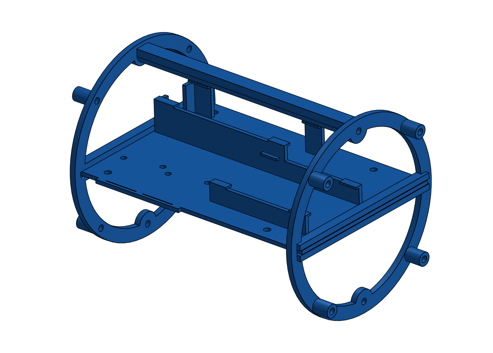
The above 3d rendering show the final design; below show the printed parts being glued together.
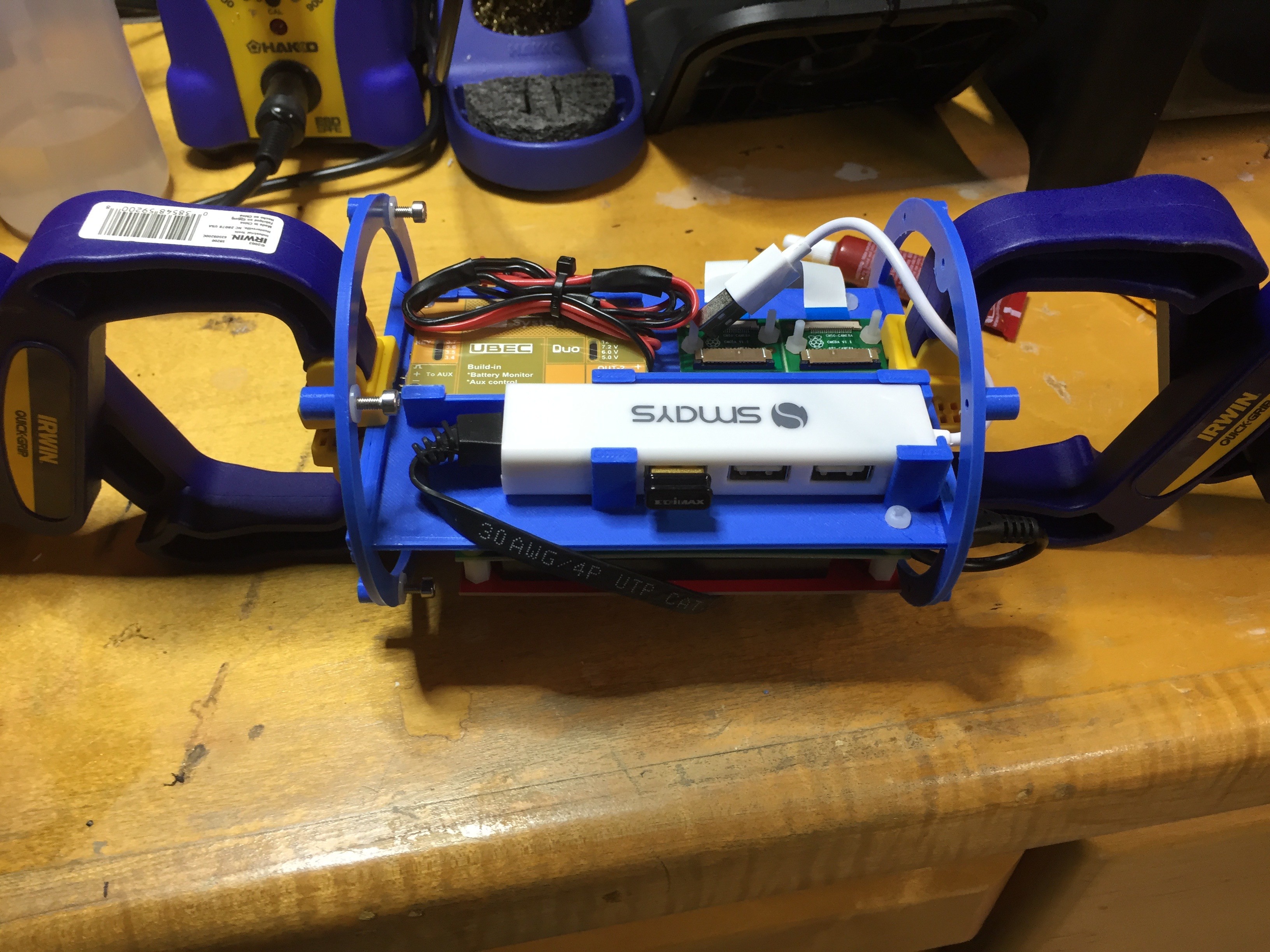
This new setup has proved much easier to work with, especially when the boards are removed from the ROV.
I've been struggling for some time with the thrusters causing the ESCs to reset. I've previously diagnosed this issue to various things, including poor power supply to the thrusters, a floating earth, a need for more decoupling on the controller board, and restricting the absolute power consumption of all the thrusters. But, while all these things have seemed to help a bit, nothing has made the issue go away completely.
While testing the new thruster design on my bench the other day using a simple servo tester, I was surprised to see I could still make the ESC reset even though everything was being run from a bench supply. This got me wondered - could the motors themselves be the problem? I chose cheap-o motors when I started out, partly because I knew they'd fail over time and so didn't want to spend a lot of money on them, and partly to see what I could get away with. Maybe I was being too cheap? So I've decided to upgrade the motors to something a little better.
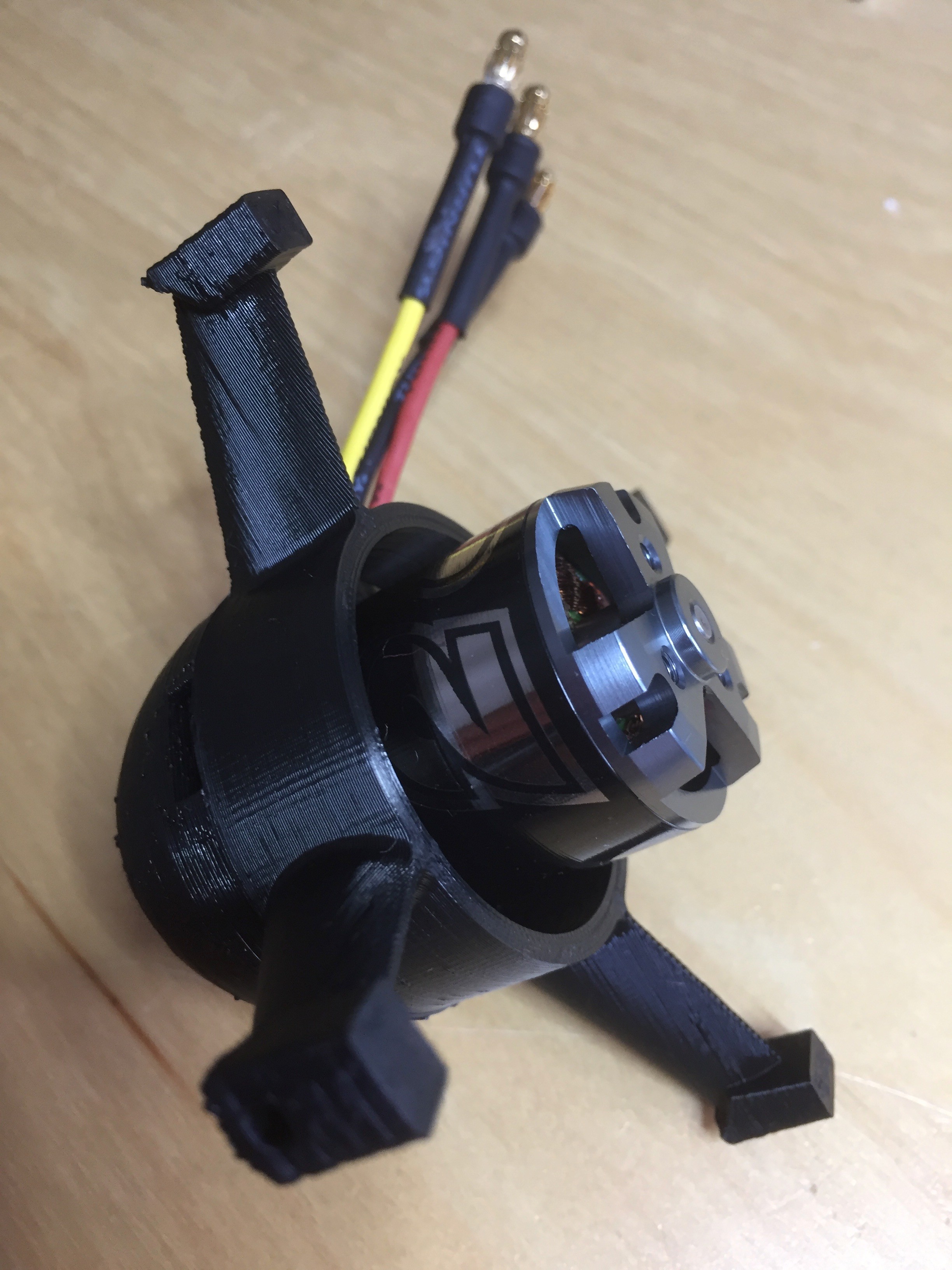
I chose the NTM 28-30S 800kV (available from Hobby King for $10 or from Amazon if you want to spend twice the money but don't want to wait); more expensive but hardly bank breaking. These are very similar in size to the old motors, but I still needed to tweak the thruster housings a little to make them fit. One big plus was the ability to bolt the props onto the motor rather than relying on a friction fit.
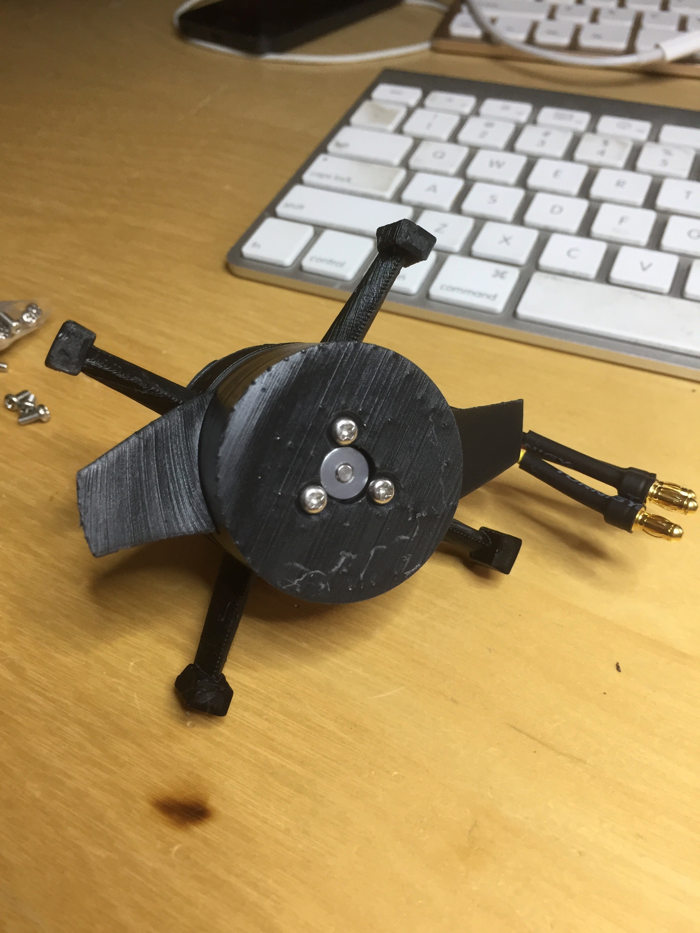
The final thrusters look identical (unsurprisingly).
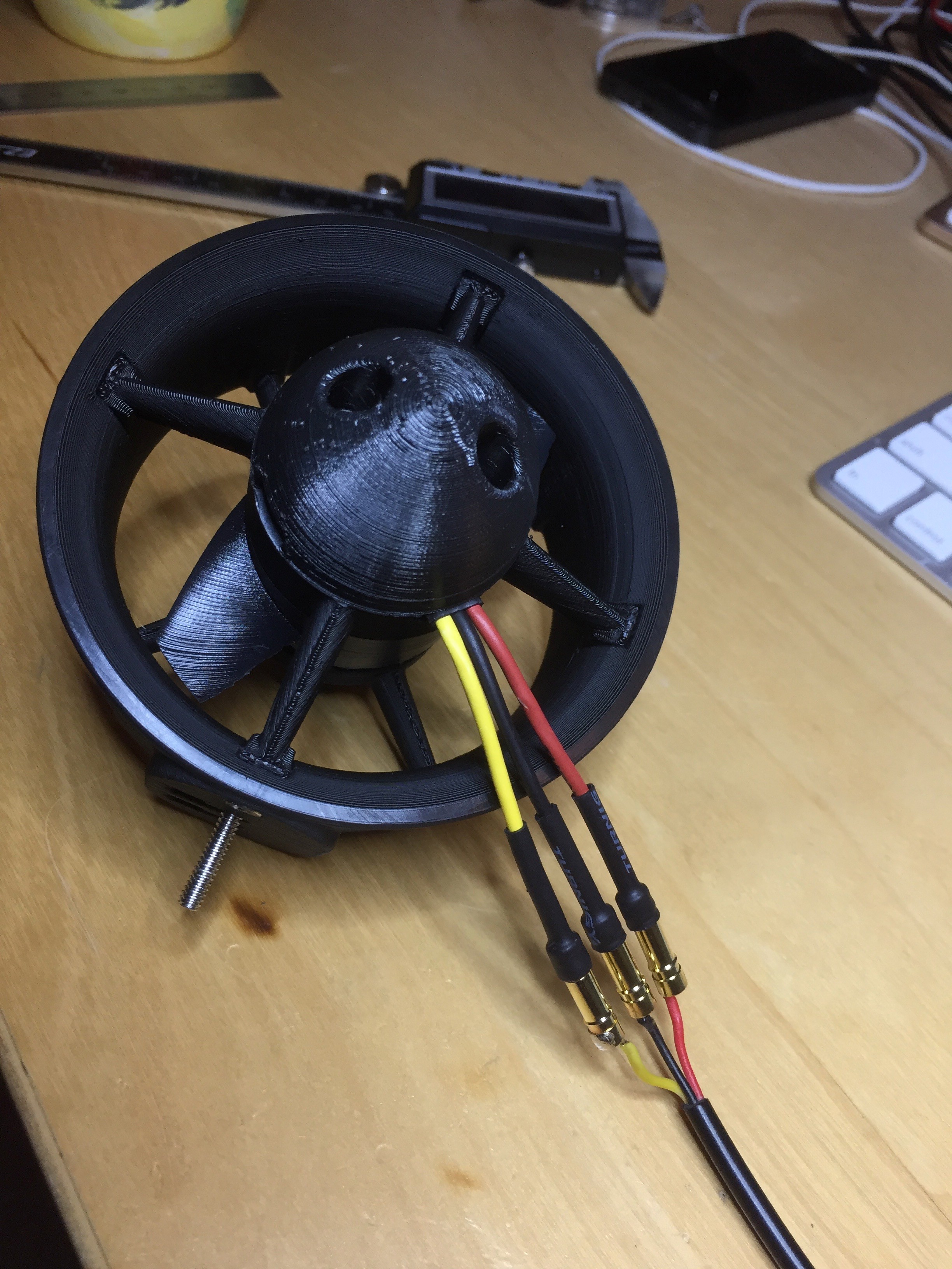
The bench tests looked promising so now I just need to buy a few more and test a set on the ROV.
Once you have a 3D printer, every problem looks like something you can fix with a 3D printer. After printing some new thrusters, I've also updated the tube mounts with some custom 3D printed pieces.

In the photo you can see them in blue (some of the new thrusters, printed in black, are also shown).
My current ROV thrusters are, shall we say, a bit of a hack. There were put in place at the very beginning of this project and not really changed much since then. As I've been finding now I have the thing (occasionally) in the water, their not very efficient.
I've pondered for a while switching them the the very nice Blue Robotics T100 thrusters - but at ~$120 each, and I've got 10, that'd be quite expensive.
However, Blue Robotics are nice enough to provide all their CAD files, so I decided I'd take their design and adapt it for my cheap motors. The result is shown below:
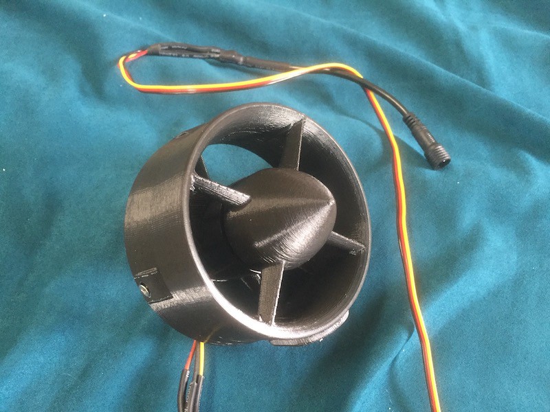
For full details on how to print and assemble this, see https://hackaday.io/project/18036-cheap-rov-thruster
Of course, while these are much cheaper than the T100, they're no more waterproof than my current thrusters - just a lot better designed. I'll be replacing my current thrusters over the next few weeks and it will be interesting to compare the performance before and after.
Since my last update, I've been ponding how best to test adding capacitors to the ESC control board. I don't want to just add and hope (relying on a vague sect of the decoupling religion), I want to be able to test. I also didn't want to spend my entire day at the pool debugging things, especially when I'd have to drag the ROV out to do various bits of soldering. However, if I tried the failing scenario in air, the motors don't cut out because they don't need a much current when running in the air. After some bench experiments I discovered that if I turned one motor full on, full off, and then full on again, I could make the controller reset.
So, with a testable environment I added some *big* capacitors - two 2,220uF caps.
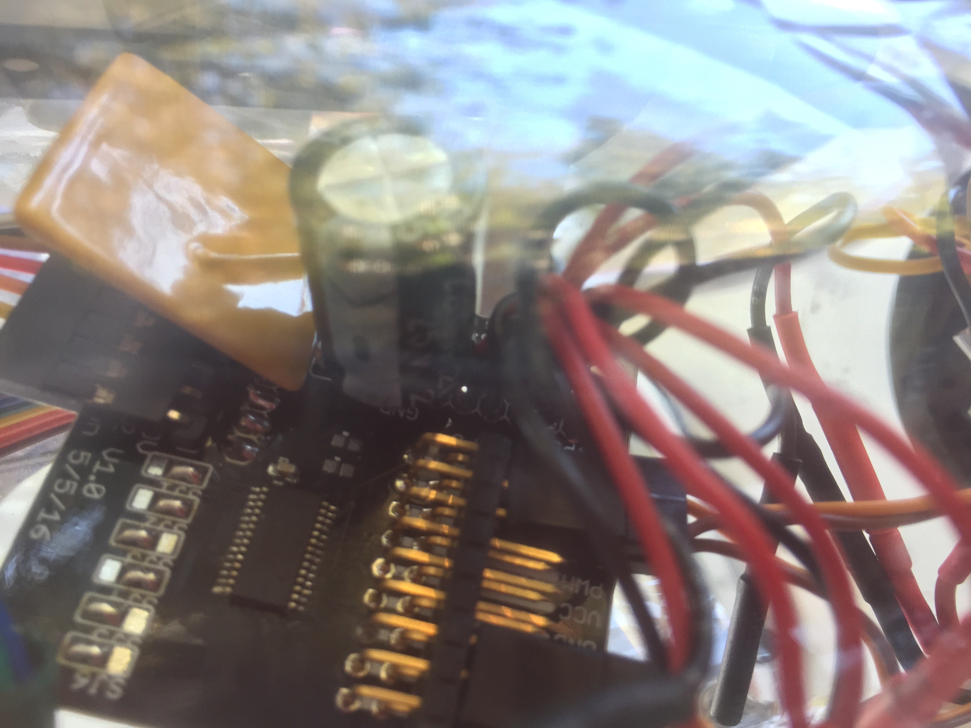
These were soldered across the main motor power supply on the controller board. Once added, I the ROV passed the on/off/on test. So success!
Next I wanted to return to the power ramp problem. During my last attempt to debug the PIDs I added a quick-and-dirty power ramp to avoid turning sudden power spikes. This worked okay, but I actually have a "proper" ramp built into the PWM controllers (written in fast and smooth C++ code) and it made more sense to use this. So I ditched the old power ramp and am now using the PWM version ... and it's *so* much smoother and better. I can ramp up 4 motors to max power simultaneously without overloading the system, which I could never do before.
Back in the pool, and the PIDs now work flawlessly, even if I start tugging the ROV around. Before the ESCs would overload, but not anymore.
The video above (portrait - sorry) shows the balance mode being enabled. The laptop screens show the artificial horizon adjusting, then the camera pans to the ROV in the pool. The ROV is not current balanced and does not sit neutrally in the pool. With balance enabled the motors adjust its position so that it does. My various attempts to dislodge this are all corrected quickly by the software.
Back in the pool today with the new polyfuses. Despite bumping these up to 10A each, I was still seeing the thrusters reset sometimes - so what was going on. Well looks like a few things. First, when I disable then enabled the balance system (that's the PIDs which keep the craft positioned in the water according to the IMU and user's requirements) I wasn't clearing all the old data out of the PIDs. This would sometimes mean a sudden change thrust from 0 to something quite big. This appears to generate a current spike which resets the thruster controller. Second, if I physically pushed the craft violently around an axis, the PIDs attempts to correct this would also result in a large current spike.
The software fix for this was to make sure I reset *everything* when I restarted the balance system, and also limit the rate at which a thruster could change speed, so limiting the potential for current spikes. Both these fixes worked very well and the craft now balances correctly.
But ... I can't help but feel I really have a hardware issue here. Power electronics is not my domain, but I'm wondering if sudden changes in the amps being consumed by the ESCs is causing problems for the nearby PWM chip. While that's on a separate power supply and has basic decoupling, I wonder if the shared ground is as issue in some way?
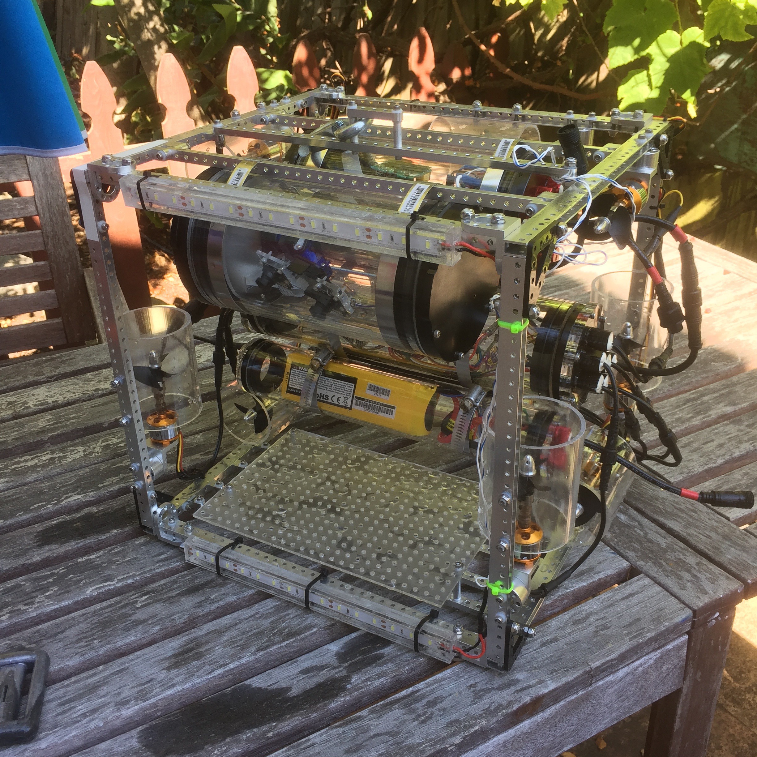
Back in the pool today after a series of major upgrades. The main electronics boards in now on revision 1.2. Mostly this is just fixing various error from 1.1, although it does include lots more servo connections (for later robot arm use) and a beefier current resistor for monitoring the main battery. The motor controllers are now in their own air tight tube, and the battery (a LiPo now) is mounted in a separate tune underneath. You can see (vaguely) the layout in the below picture:
With the four z-axis motors attached (the ones pointing up-down) I finally had chance to work on calibrating the PIDs. The PIDs essentially keep the ROV stable in the water based on the input from the IMU. A made some good process here. The current weight distribution of the ROV is not good, and without power is sinks down farther in one corner. Once Balance mode is engaged, the current PID values bring the ROV back into a neutral position - success!!
However (because there's always one of those) once the motor control boards start to draw about 60W from the battery, the polyfuse on the board triggers and the motors reset. The voltage is about 12V, so that's only ~4A, or 1A per ESC. That's not very much and the system can certainly handle more power. I'm going to investigate switching the polyfuses.
Because I had to take things to pieces to check for water damage, I decided it was a good time to rev the main controller board. This was damaged a while ago when the first attempt at waterproof ESCs failed. I patched it up to get it working again and also did a redesign to improve power distribution and add more servo controllers (for the eventual robot arm). I'd put off ordering the new PCB, but now seems like a good time to commit to this improvement.
Create an account to leave a comment. Already have an account? Log In.
No, but it isn't designed to be. Just flush the motors with fresh water after a dive to keep them from corroding. Even if the motors only survive a few dives, they are so cheap to essentially be disposable.
I've been working on a ROV myself with similar 3D printed thrusters using ~$7 quadcopter motors, and if I get 2 - 3 dives per motor, I'm fine with that.
Hello!, I'm building an ASV in Argentina and using a couple of T100 thruster. Looking for a mounting I found you on thingiverse.
What a wanderfull work!!!!!
I'm wondering how much thrust do your thruster get. Could it more thrust that original T100?
That's so cool! Can I ask you what are your considerations for choosing the BNO055 IMU? I'm doing an autonomous boat but I'm struggling to choose the right IMU and I really need some suggestions :D https://hackaday.io/project/10652-green-powered-sailboat
Sorry - I missed your question when you asked it. I choose the BNO055 because it did all the fiddly calibration and math to convert the various physical sensors into roll, pitch and yaw. I could have written (stolen) that code myself, but it was nice to pay a few extra bucks and have something else worry about it.
Those sound good. I worry about how long they last in salt water which is why I'm being a cheapskate.
Cool project Tim. I'm interested in doing something similar based on an Actobotics cube frame like yours. Do you think the motors will need gear reduction?
I chose motors with low kV, which means (apparently) that you get less RPMs and more torque per volt applied. I would go lower than I have, but these ones were low enough and dirt cheap. Of course I have yet to run this thing through a set of proper propulsion tests so I've yet to see who good - or not - a choice these are.
Well the price is right for those motors for sure. I did find some 400kV brushless motors on hobby king for about $40 each. I might try those if these ones don't work out. I'll send you a link to my project page once it has some content. Cheers
You can heat shrink the DC motor then pot it with a 3M potting to prevent it from corroding in salt water. The down side is the DC motor may overheat.
I am really curious how the brushless motors will hold up to saltwater. I would expect the bearings, cores, and shafts to have problems with corrosion.
I'm curious too. I'm thrown very cheap motors on this thing, so it's a cost/time-to-failure tradeoff. I've also considered a few things to paint the motors with which might improve them, but I want to see how things fail before I put stainless steel bearings at this.
Perhaps you could use a rotary seal? This can be a dedicated part or an appropriately sized well greased O-ring.
Here are some examples below:
Usually, the coating on the windings get abraded by sea water and sediment and short circuit. If this doesn't kill the motor then corrosion of the bearings and or shafts will do it in. As Tim said, the cost/time-to-failure consideration is very important here.
That's interesting, I would have expected the corrosion of the cores to be more of a problem. Now if the problem is just with abrasion, perhaps this can be fixed by keeping sediment out of the windings by adding a small cover for the motors. Or even pot the windings in epoxy.
The bearings could be replaced with corrosion resistant plastic bearings or even just a plastic bushing. It shouldn't be too hard to replace the shaft with something more corrosion resistant.
The cores could also be an issue now that I think of it. For a motor with an aluminum core, the replacement time would be on the order of weeks if not months. Taking an educated guess, the biggest danger of a badly corroded core is spreading corrosion. This will be one of the things I will experiment with as I have access to the ocean and I can set up some test cells with some aluminum disks to test the corrosion rates for aluminum of that scale.
Potting in epoxy seems to be the most popular way to go about doing it. Lowers the MTBF of these motors in sea water. Bushings, plastic bearings, or even stainless bearings could also be used to help control corrosion.
Shaft corrosion is likely not be such a big deal as the bearings and windings. I took it into consideration because it is in direct contact with the bearings and could possibly spread corrosion to the surrounding areas.
I avoided POE because the cables are substantially heavier and less flexible (more cores). Also, I'm measuring ~6 ohms on my cable, which would still drop 8A with 48V. Might work with lower AWG cables.
Hi Tim,
I am hopefully going to be building one of these soon and am going to try out a power line network adapter for getting the data back up.
I believe this may solve the problem of having a high speed connection to the rov over Ethernet as well as being able to supply the rov with plentiful amounts of power to run any systems you want without a major compromise. I highly doubt adding a power line converter will weigh more than the battery packs you remove and the cable should be equal in weight to that of a cat5e cable per meter.
I may also attempt using flexible fiber optics with a power main as i have the equipment and it couldn't hurt to try.
what do you think?
Hi tim,
I have been looking into a few of the home plug adapters. I even found one that has two ethernet ports on one end, and one on the other. This configuration would be perfectly suited for my application and actually cut the number of wires on the tether in half or even by 4. http://www.amazon.com/TP-LINK-TL-PA4026-KIT-Powerline-Starter/dp/B010Q29KRK/ref=pd_sim_147_3?ie=UTF8&dpID=31c2eAWH75L&dpSrc=sims&preST=_AC_UL160_SR160,160_&refRID=08P7ZDW1FYRFQJ8XJADM
I need the pair of cables for an IP camera, as using one of those is cheaper and easier to pan/tilt. I also require one for the Arduino that runs this entire mess of wires and lights, all of this all has to be done in a tight space and no ethernet switch is even small enough to fit. I believe this model should be hackable, but potentially harder to hack. This pair also communicates far faster than I need them too so updates to a full HD Video streaming system is possible in the future.
As an Aside, I have just created a Hackaday page for the Luna I project which can be found at https://hackaday.io/project/9523-luna-i-rov
-MrCullDog
Why not Power-over-ethernet? With ~48V you do not have too much loss in the transmission.
I explored POE as an easy solution to the issue of getting power down, However, The power level required for even 3 thrusters is almost 60 amps at 11v. There is no way to transmit this much power down over POE. I plan to scale this design up to a much larger ROV which could require power measured in kW. In this case. A transformer to step the voltage down from a high voltage to a lower voltage and a AC-DC converter to manage the conversion to usable power is the way to go. The issue with this is that it simply isn't practical for small ROVs. I believe that Lipo batteries are the best way to run the ROV. Although I am open to new solutions to this problem.
So basically you could just charge the batteries slowly over PoE and extend the range. Your average power consumption will be less than 660W. At least you can power the electronics, even if the batteries are down.
In really big ROVs the go the other way with the transformers: They step the voltage up for the transmission. To about 1kV for the electronics supply and about 3kV/3Ph for the 100kW Main motor which drives the hydraulics. The whole cable is several cm thick and terminates in the transformer box. I don't know if they have a battery for the electronics. The motor is mains only.
You could still use a high voltage approach, possibly with an 1:1 isolation transformer from the mains, a rectifier - even with power factor correction, if you want and go down with ~350VDC. Assuming 230V mains, but half of it (USA mains) is probably sufficient. So you save the AC/PFC section of a switch mode converter in your ROV.
@Martin I have heard of 3kV 2 or 3-Phase 400hz AC at low current being used as the supply for most ROV systems. I believe that you can get large scale generators to supply exactly that. Using mains voltage is an option its the equipment required up top and on the ROV are likely slightly bulky for what I am attempting to build ( I will explore my options with that). In fact, It may actually be quite easy to run both mains voltage and ethernet with the Home-plug interface. For the scaled up design, I will design HV circuitry to deliver the correct power to the Motors and electronics. I don't know that this vehicle will ever be built. But it has been interesting to design it and has helped with design decisions on the smaller vehicle.
At this point. Lipo Batteries seem to be the best thing to use. In the future It will be possible to add POE/mains To run at least the electronics in the event of a power loss. This way I should be able to locate it and retrieve it fairly easily.
@MrCullDog: I don' know, if I would call 3*11A exactly "low current" :-) But that was for sure a mains frequency 3Ph motor, powering the hydraulic pump. In that case the power came probably from the generators in the support ship. You do not need or want 400Hz there (losses in 5km transmission cable and the motor itself). 400Hz are often in use in aircraft for lighter transformers and for high speed motors (>3000rpm), but a hydraulic pump normally is not made for that high speed.
Of course there are many different designs.
Perhaps it is possible to use the PoE approach with a higher DC voltage. The ETH-magnetics are often rated for 1500VAC for 1 min. I would expect them to take 200 or 300VDC common mode voltage for longer time. But I dont know, how much current they can take.
http://www.deeptechoilservices.com/pdf/Quantum_9.pdf This document details some of the superficial details of an ROV used in the real world. Surprisingly, It uses "normal" 3-Phase power at somewhere around 380V @ 475kva. I honestly have no clue now that I look again where I got the number 3kv @ 400hz ( Will do more research) Potentially, they are using that to power topside equipment which converts it to usable power. The reason for this confusion may be that technical details for these machines are very difficult to nail down, as they are often proprietary and protected under NDA's and special agreements. Although ~300v over POE like circuitry sounds risky, I will experiment with the limits of CAT-5e cabling and POE cabling as removing the pair of batteries from the ROV would certainly be a nice thing to do.
Hi tim,
I have yet to assemble my own ROV. I am in the phase of gathering parts and finalizing designs at the moment and plan to release some initial documentation this week with everything going open source once the project is fully underway. I will send a link when I have it ready.
A few things to note about the beads, they are particularly suited for buoyancy (They use Syntactic Foam on the professional ROVs), I don't know much about the sealing properties, but it could possibly work for sealing connectors. For the enclosure itself, Oil compensation is the way to go for deep diving, as oil is non compressible and will prevent the electronics tube from collapsing well above the rated pressure of your tube. The benefit of this it that there is no pressure differential between the inside and outside, so long as you can keep the oil from leaking out (This can be challenging) it will stay sealed. The down side, as you probably know, is that all of your electronics get coated in oil which can be very difficult to remove if you need to make a modification. Taking all of this into consideration, oil is likely the best way to implement all of this.
The thrusters that I am using are 3D printed Kort nozzles that I found at http://svseeker.com/rov_thrurters.htm. They can generate about 4 pounds of thrust each, but are substantially more expensive than what you have implemented. If you don't have access to a 3D printer the cost is substantially higher.
As for the manipulator, It will very likely be the first to go in the depth test. Professional ROV's use hydraulics to move the joints. But on an ROV this scale, Implementing Hydraulics is not practical. And thus loosing one or two servos is much preferred to having to build a hydraulics system. The servos may continue operating even while flooded with water, But I wouldn't count on this as the inside could begin to corrode and potentially even short as well. I have been thinking about using stepper motors for this as they are brushless motors. However they require more code and are heavy when compared to servos, they also consume much more power, but have greater gripping/lifting force. As always, more research into ROV manipulators is required.
The only area that I have been struggling with is the tether. Actual neutrally buoyant cable is incredibly expensive to buy and Ethernet cable doesn't really float. So I am really not sure what to use to send signals down and back.
-MrCullDog
For tether, check out the work the OpenROV folks did to get the Homeplug adaptor working - this is what I'm using for comms to the surface (ethernet over 2 small gauge wires). I had originally planned to send power down the tether too (it can live on the same pair of wires as the comms) but I'd have to use too high a voltage or too large gauge wire to make this practical. The OpenROV folks also sell neutrally buoyant kevlar tether (http://store.openrov.com/collections/experimental/products/neutrally-buoyant-tether) but it's rather costly ($5 a meter).
I think, the time the servos will continue to operate when flooded is to be measured in seconds. And "water resistant" servos do not mean in any sense of the word "pressure resistant". So I think the only way to go is to fill them also with oil. At least gears like some lubrication :-) Electrical brushes not so much, so probably you have to find - or make- brushless servos, best with hall effect position encoders. About the buoyancy of the cable: Is it possible to fix plastic floaters in regular distance to the cable? Like the egg shaped things used for fishing nets?
Hi there,
Thanks so much for your comments - I really appreciate them. I haven't consider the specific depth this craft can go to yet - I've yet to get it into the water and this is definitely prototype-1. I'm going to be very interested in what depth things fail; the manipulator will be the first to go I'm sure.
Thrusters are an area I'm particularly interested in (hence the ridiculous number of them). The short term goal is for the ROV to be "self balancing" - that is, to not roll/pitch while I drive it around. I have a lot of software to develop yet.
The glass beads sound very interesting as an alternative to filling things with oil. So far I've resisted anything that permanent.
I'd like to start out by saying this is exceptional work! Looks very professional. I do have a few suggestions for you that I have found building my own ROV:
1. Observe the professional ROV's form Woods Hole, Scripps, Oceaneering, Odyssey, etc, and to see how they configure thrusters, manipulators, etc. A good place to start is with this video. Keep in mind that we have the opportunity to try things that they simply cant. So use these as a place to start but try to come up with your own solutions to a problem as well. http://oceanexplorer.noaa.gov/okeanos/explorations/ex1302/new_rov_video.html
(they show lots of detail about an ROV that costs an unbelievable amount of money)
2. Syntactic foam is some amazing stuff. It is well worth the money spent. I am not sure of your target depth, but 3M makes the Glass beads that go into it, and you can get 5 lbs for about $50 here: http://www.aircraftspruce.com/catalog/cmpages/bubbles.php?clickkey=10403 It is the K20 series which should be good to somewhere around 1100 ft. This will be mixed with epoxy to create the rigid foam. I plan to test the ratio established on the website soon and will report the results.
3. As for my own project. It is relatively simple compared to what you are building. It only occupies about a cubic foot of space and has a 3 thruster layout with no manipulator. It has a T-slotted frame so adding a manipulator later is not difficult. The main reason for this is minimizing passthroughs, which can be a massive headache if you discover that one is leaking. As a final aside I am using this connector to attach the ROV to the tether that runs to the surface vessel. This plug actually goes into the hull through a BlueRobotics through-hull connector to allow it to be quickly disconnected/connected on the surface: http://www.amronintl.com/rmg-4-mp-rmg-series-in-line-rubber-molded-connector-4-male-pins-with-18-in-pigtail-of-18-gauge-so-sjoow-aiw-k-cable-for-kmdsi-helmets.html It is low cost and good to 20,000 PSI.
You are doing a great job with the engineering and layout of this machine. It is very well executed. Keep up the good work!
Become a member to follow this project and never miss any updates
By using our website and services, you expressly agree to the placement of our performance, functionality, and advertising cookies. Learn More

 Matt
Matt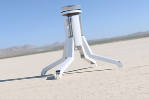
 Paul Crouch
 roger_archibald
 Morning.Star
is the thruster really waterproof