-
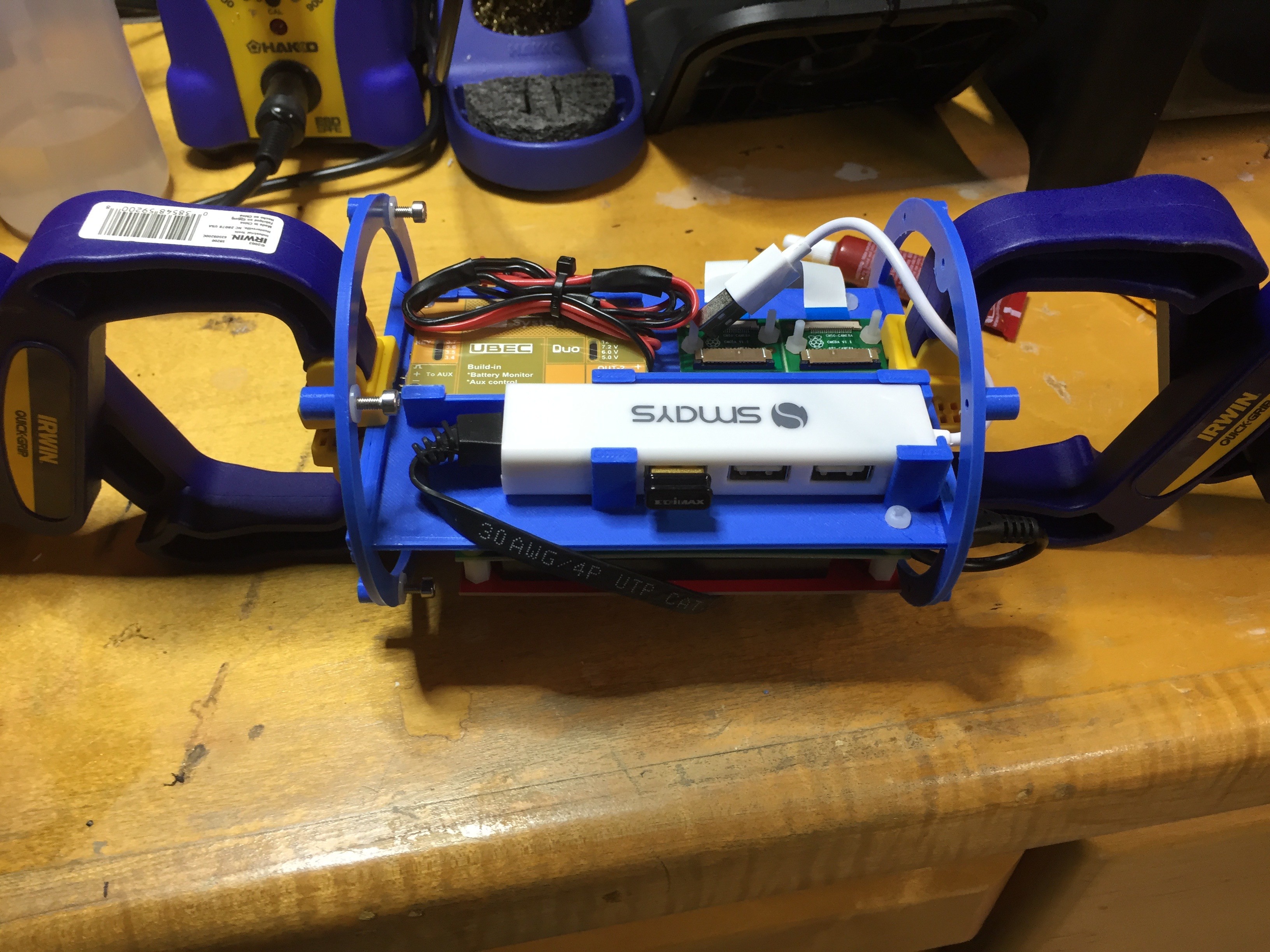
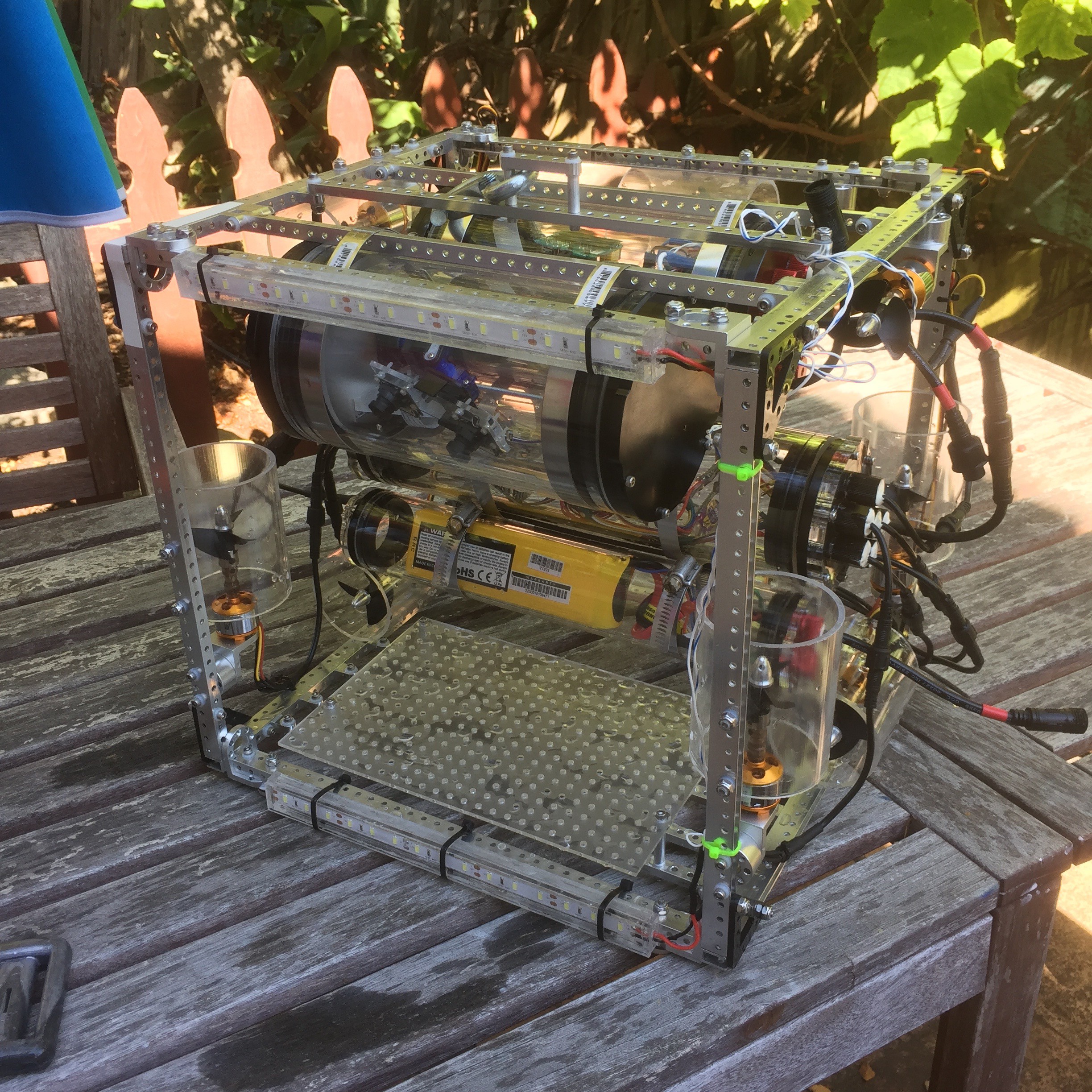
Rebuild so far: photo
02/12/2017 at 20:59 • 0 comments -
Tube mount STLs
02/12/2017 at 20:50 • 0 commentsJust updates the project with the STL for all the tube and board mounts. I've also added mounts for single 2", 3" and 4" tubes.
-
New internal mounts
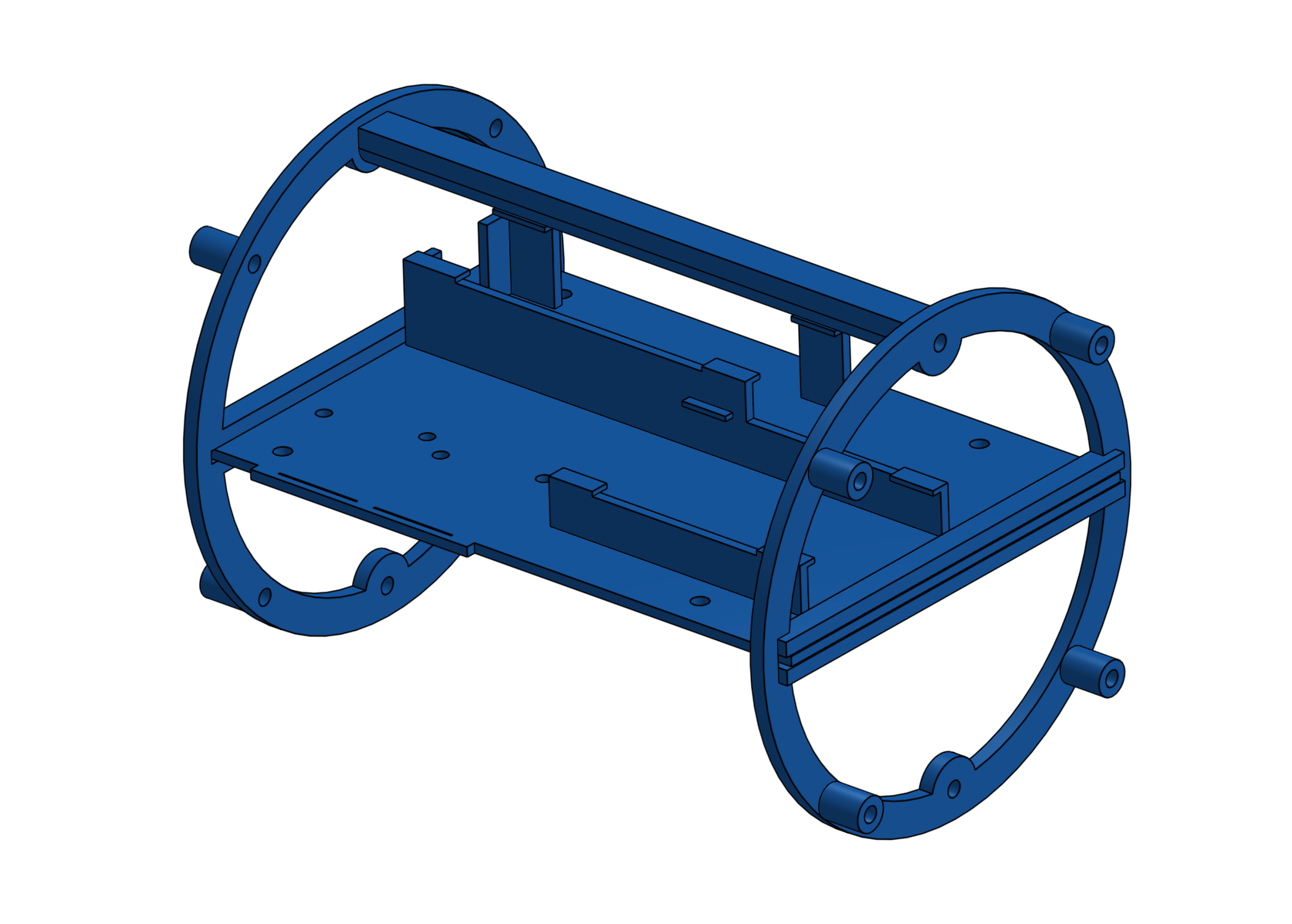
02/11/2017 at 01:26 • 0 commentsAs part of the 3D printing rebuild, I've printed proper supports for the internal Raspberry Pi Computer Module board, daughter board, and various additional components. The original mount was a simple piece of laser cut acrylic to which the components were screwed or taped. The new mount was designed to have a custom fit for the various components, as well as bolting securely to the endcaps.
The above 3d rendering show the final design; below show the printed parts being glued together.
This new setup has proved much easier to work with, especially when the boards are removed from the ROV.
-
The big thruster rebuild
02/06/2017 at 01:19 • 1 commentI've been struggling for some time with the thrusters causing the ESCs to reset. I've previously diagnosed this issue to various things, including poor power supply to the thrusters, a floating earth, a need for more decoupling on the controller board, and restricting the absolute power consumption of all the thrusters. But, while all these things have seemed to help a bit, nothing has made the issue go away completely.
While testing the new thruster design on my bench the other day using a simple servo tester, I was surprised to see I could still make the ESC reset even though everything was being run from a bench supply. This got me wondered - could the motors themselves be the problem? I chose cheap-o motors when I started out, partly because I knew they'd fail over time and so didn't want to spend a lot of money on them, and partly to see what I could get away with. Maybe I was being too cheap? So I've decided to upgrade the motors to something a little better.
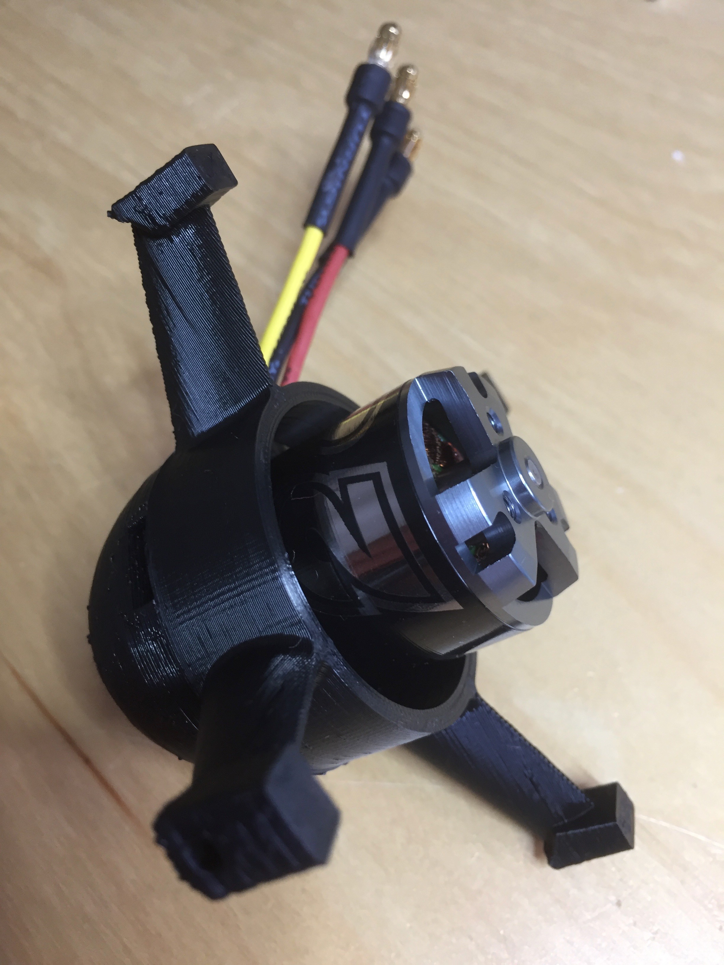
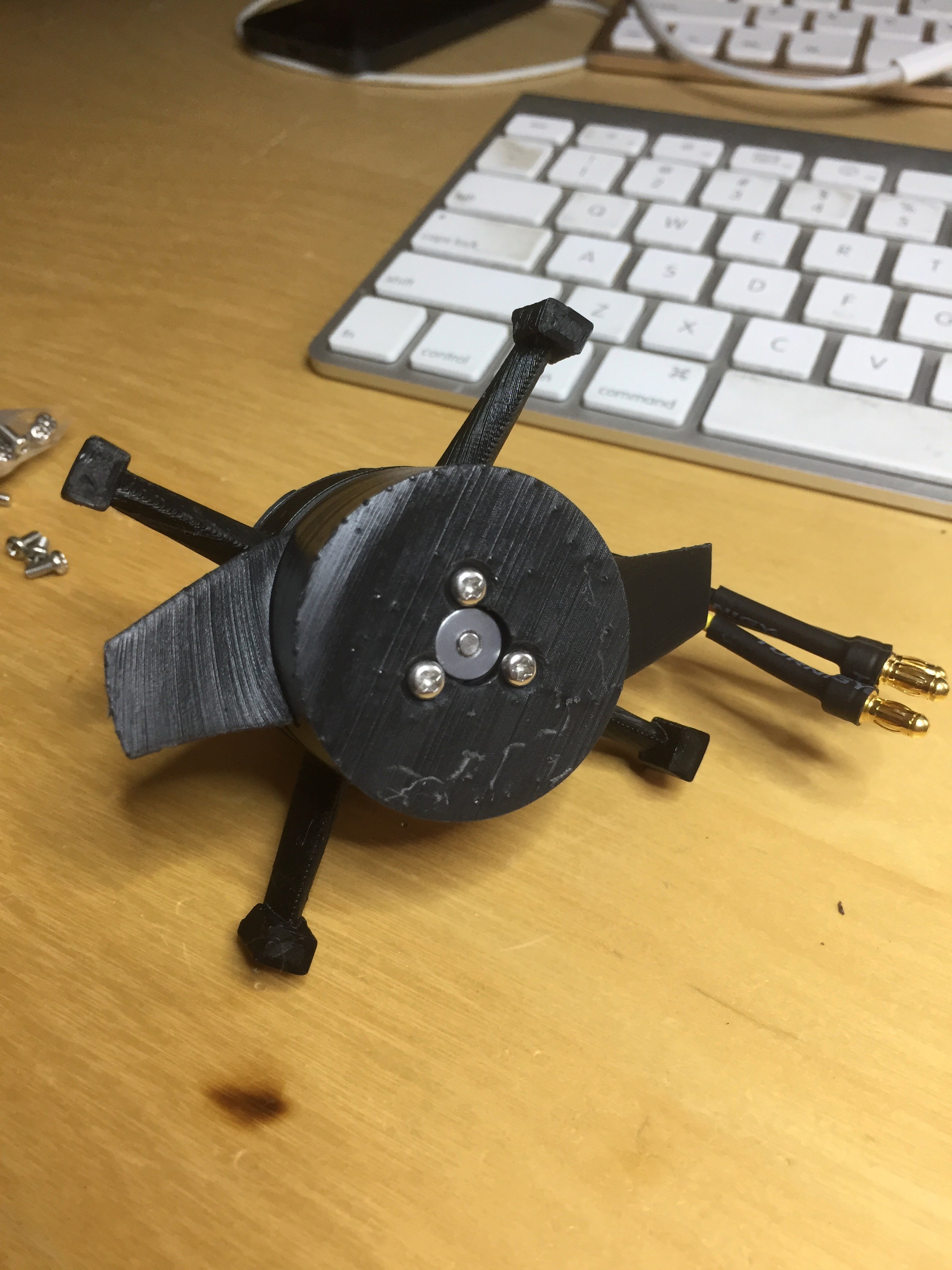
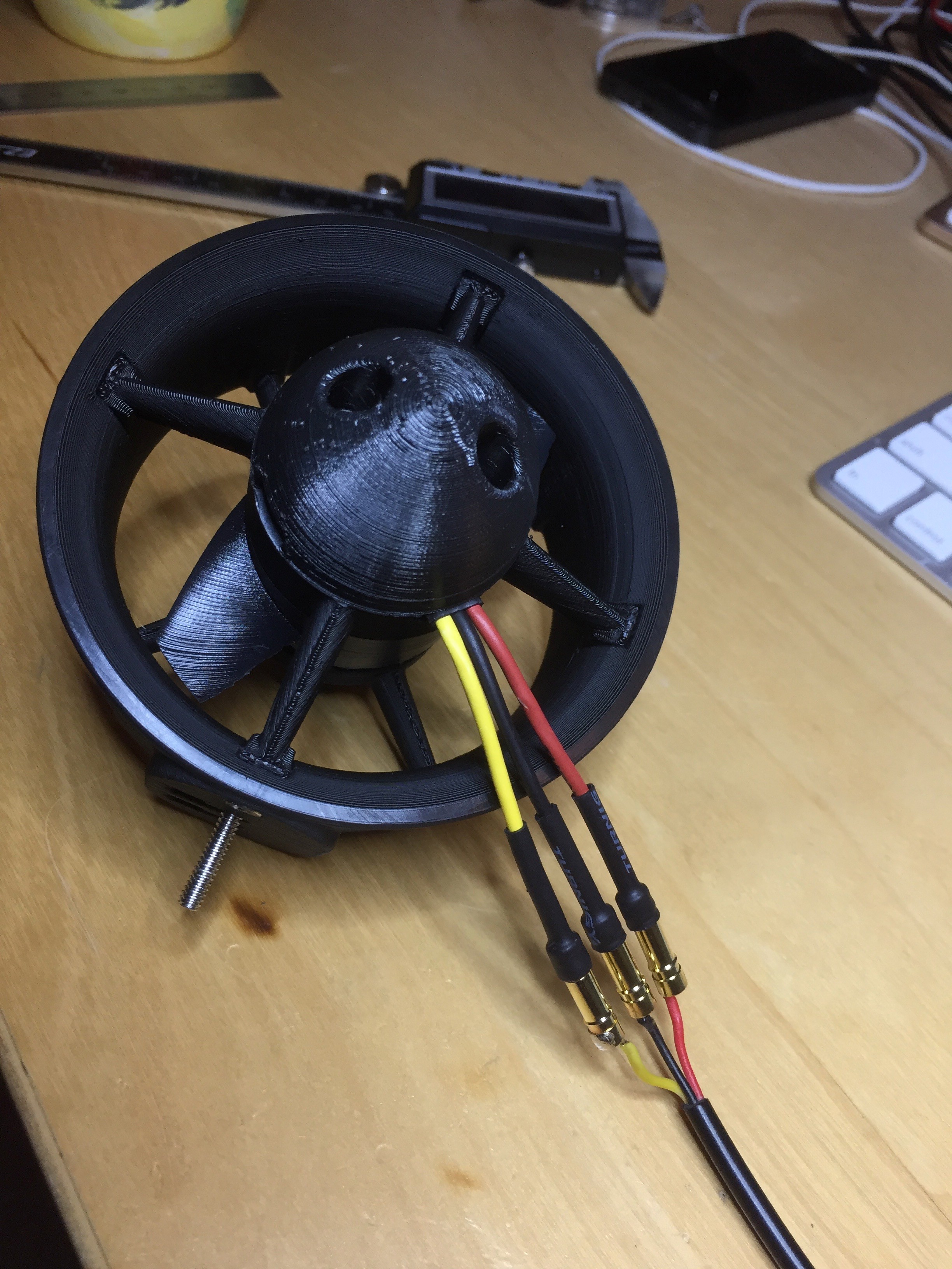
I chose the NTM 28-30S 800kV (available from Hobby King for $10 or from Amazon if you want to spend twice the money but don't want to wait); more expensive but hardly bank breaking. These are very similar in size to the old motors, but I still needed to tweak the thruster housings a little to make them fit. One big plus was the ability to bolt the props onto the motor rather than relying on a friction fit.
The final thrusters look identical (unsurprisingly).
The bench tests looked promising so now I just need to buy a few more and test a set on the ROV.
-
3D Thrusters and mounts
01/21/2017 at 06:27 • 0 comments -
3D Printed Thrusters
11/13/2016 at 06:09 • 0 commentsMy current ROV thrusters are, shall we say, a bit of a hack. There were put in place at the very beginning of this project and not really changed much since then. As I've been finding now I have the thing (occasionally) in the water, their not very efficient.
I've pondered for a while switching them the the very nice Blue Robotics T100 thrusters - but at ~$120 each, and I've got 10, that'd be quite expensive.
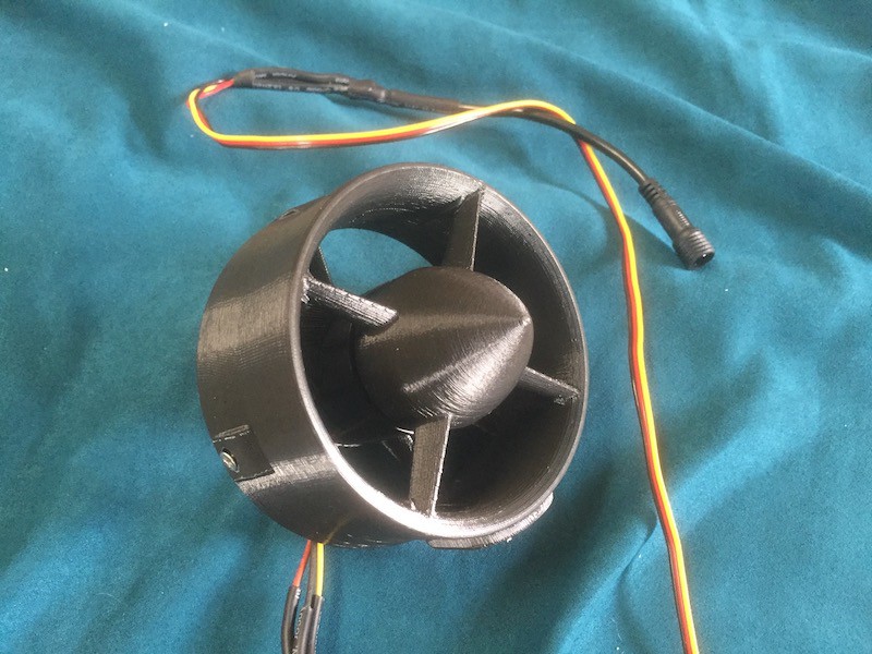
However, Blue Robotics are nice enough to provide all their CAD files, so I decided I'd take their design and adapt it for my cheap motors. The result is shown below:
For full details on how to print and assemble this, see https://hackaday.io/project/18036-cheap-rov-thruster
Of course, while these are much cheaper than the T100, they're no more waterproof than my current thrusters - just a lot better designed. I'll be replacing my current thrusters over the next few weeks and it will be interesting to compare the performance before and after.
-
Capacitors and better power ramps
09/13/2016 at 21:27 • 0 commentsSince my last update, I've been ponding how best to test adding capacitors to the ESC control board. I don't want to just add and hope (relying on a vague sect of the decoupling religion), I want to be able to test. I also didn't want to spend my entire day at the pool debugging things, especially when I'd have to drag the ROV out to do various bits of soldering. However, if I tried the failing scenario in air, the motors don't cut out because they don't need a much current when running in the air. After some bench experiments I discovered that if I turned one motor full on, full off, and then full on again, I could make the controller reset.
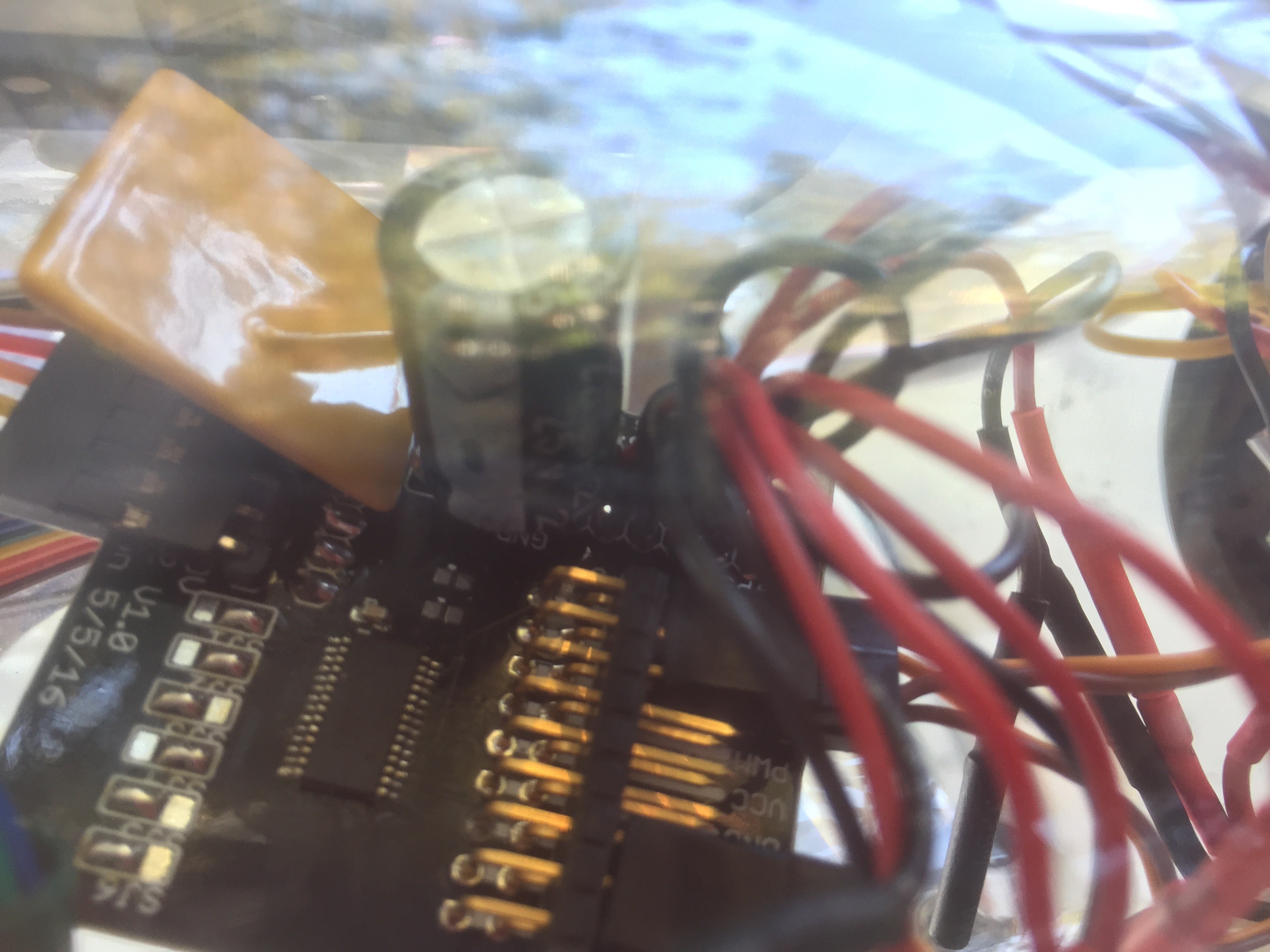
So, with a testable environment I added some *big* capacitors - two 2,220uF caps.
These were soldered across the main motor power supply on the controller board. Once added, I the ROV passed the on/off/on test. So success!
Next I wanted to return to the power ramp problem. During my last attempt to debug the PIDs I added a quick-and-dirty power ramp to avoid turning sudden power spikes. This worked okay, but I actually have a "proper" ramp built into the PWM controllers (written in fast and smooth C++ code) and it made more sense to use this. So I ditched the old power ramp and am now using the PWM version ... and it's *so* much smoother and better. I can ramp up 4 motors to max power simultaneously without overloading the system, which I could never do before.
Back in the pool, and the PIDs now work flawlessly, even if I start tugging the ROV around. Before the ESCs would overload, but not anymore.
The video above (portrait - sorry) shows the balance mode being enabled. The laptop screens show the artificial horizon adjusting, then the camera pans to the ROV in the pool. The ROV is not current balanced and does not sit neutrally in the pool. With balance enabled the motors adjust its position so that it does. My various attempts to dislodge this are all corrected quickly by the software.
-
ESC Power Ramps
09/02/2016 at 19:42 • 0 commentsBack in the pool today with the new polyfuses. Despite bumping these up to 10A each, I was still seeing the thrusters reset sometimes - so what was going on. Well looks like a few things. First, when I disable then enabled the balance system (that's the PIDs which keep the craft positioned in the water according to the IMU and user's requirements) I wasn't clearing all the old data out of the PIDs. This would sometimes mean a sudden change thrust from 0 to something quite big. This appears to generate a current spike which resets the thruster controller. Second, if I physically pushed the craft violently around an axis, the PIDs attempts to correct this would also result in a large current spike.
The software fix for this was to make sure I reset *everything* when I restarted the balance system, and also limit the rate at which a thruster could change speed, so limiting the potential for current spikes. Both these fixes worked very well and the craft now balances correctly.
But ... I can't help but feel I really have a hardware issue here. Power electronics is not my domain, but I'm wondering if sudden changes in the amps being consumed by the ESCs is causing problems for the nearby PWM chip. While that's on a separate power supply and has basic decoupling, I wonder if the shared ground is as issue in some way?
-
Too small polyfuses
08/13/2016 at 23:35 • 0 commentsBack in the pool today after a series of major upgrades. The main electronics boards in now on revision 1.2. Mostly this is just fixing various error from 1.1, although it does include lots more servo connections (for later robot arm use) and a beefier current resistor for monitoring the main battery. The motor controllers are now in their own air tight tube, and the battery (a LiPo now) is mounted in a separate tune underneath. You can see (vaguely) the layout in the below picture:
With the four z-axis motors attached (the ones pointing up-down) I finally had chance to work on calibrating the PIDs. The PIDs essentially keep the ROV stable in the water based on the input from the IMU. A made some good process here. The current weight distribution of the ROV is not good, and without power is sinks down farther in one corner. Once Balance mode is engaged, the current PID values bring the ROV back into a neutral position - success!!
However (because there's always one of those) once the motor control boards start to draw about 60W from the battery, the polyfuse on the board triggers and the motors reset. The voltage is about 12V, so that's only ~4A, or 1A per ESC. That's not very much and the system can certainly handle more power. I'm going to investigate switching the polyfuses.
-
Main board update
07/28/2016 at 21:32 • 0 commentsBecause I had to take things to pieces to check for water damage, I decided it was a good time to rev the main controller board. This was damaged a while ago when the first attempt at waterproof ESCs failed. I patched it up to get it working again and also did a redesign to improve power distribution and add more servo controllers (for the eventual robot arm). I'd put off ordering the new PCB, but now seems like a good time to commit to this improvement.
 Tim Wilkinson
