-
Failure? Yes, that's still an option
07/22/2016 at 00:03 • 1 commentAfter a month away, finally got the ROV back in the tub today.
First, the good news. The new tubes sizes and arrangements means the ROV is much less buoyant than before. I was able to remove all the extra lead weight which still left the ROV slightly negatively buoyant, so I'll need to look at a way to neutralize that (maybe some sort of foam). However, despite that, I was able to make a start on re-calibrating the PIDs for the thrusters.
But .. a little way into this I noticed that the thrusters on one side of the ROV were no longer running. Quickly hauling it out of the tub I was horrified to discover water was in the battery/ESC tube causing a short, shutting down the controller on one side of the ROV. I guess the new fuses did their job.
So now, I'm just drying things out and waiting to see what damage is permanent.
![]()
Behold - soggy ESCs :-(
-
Decreasing buoyancy with new electronics tube
06/12/2016 at 01:21 • 0 commentsBecause I have been rebuilding parts of my ROV due to the blow-up of my original ESC design, I've taken the opportunity to reduce the size of the tubes which house the electronics and cameras. When I started out, I had no real understanding of how much space these two systems would take, nor how buoyant two large, mostly empty, tubes of air would be. The counter this buoyancy I've had to add more weight; and that just makes the whole thing heavier for nor real gain.
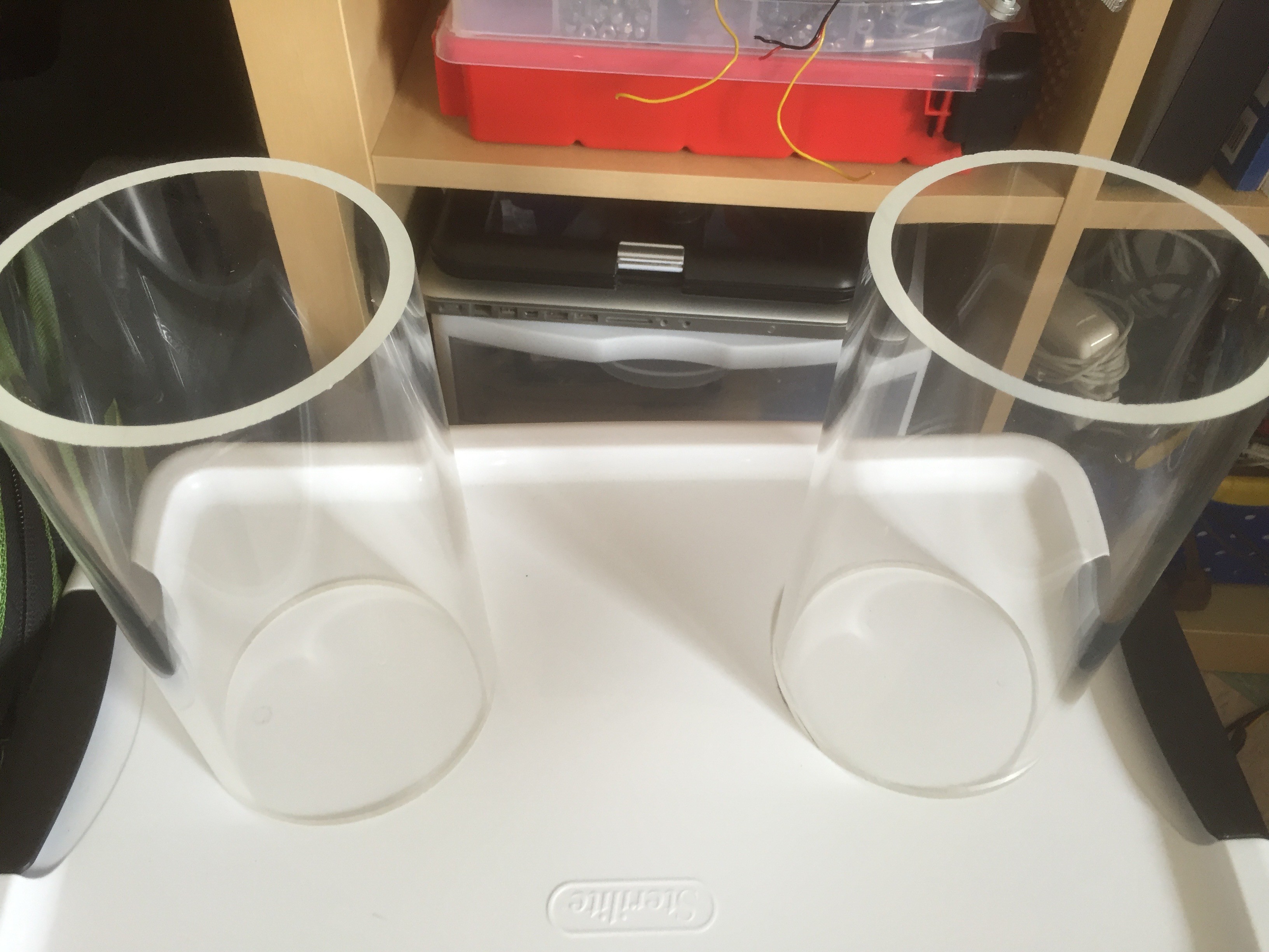
So, I've replaced the original Blue Robotics tubes with custom sized Blue Robotics tubes (195mm each - a reduction of about 1/3 on the default tube size).
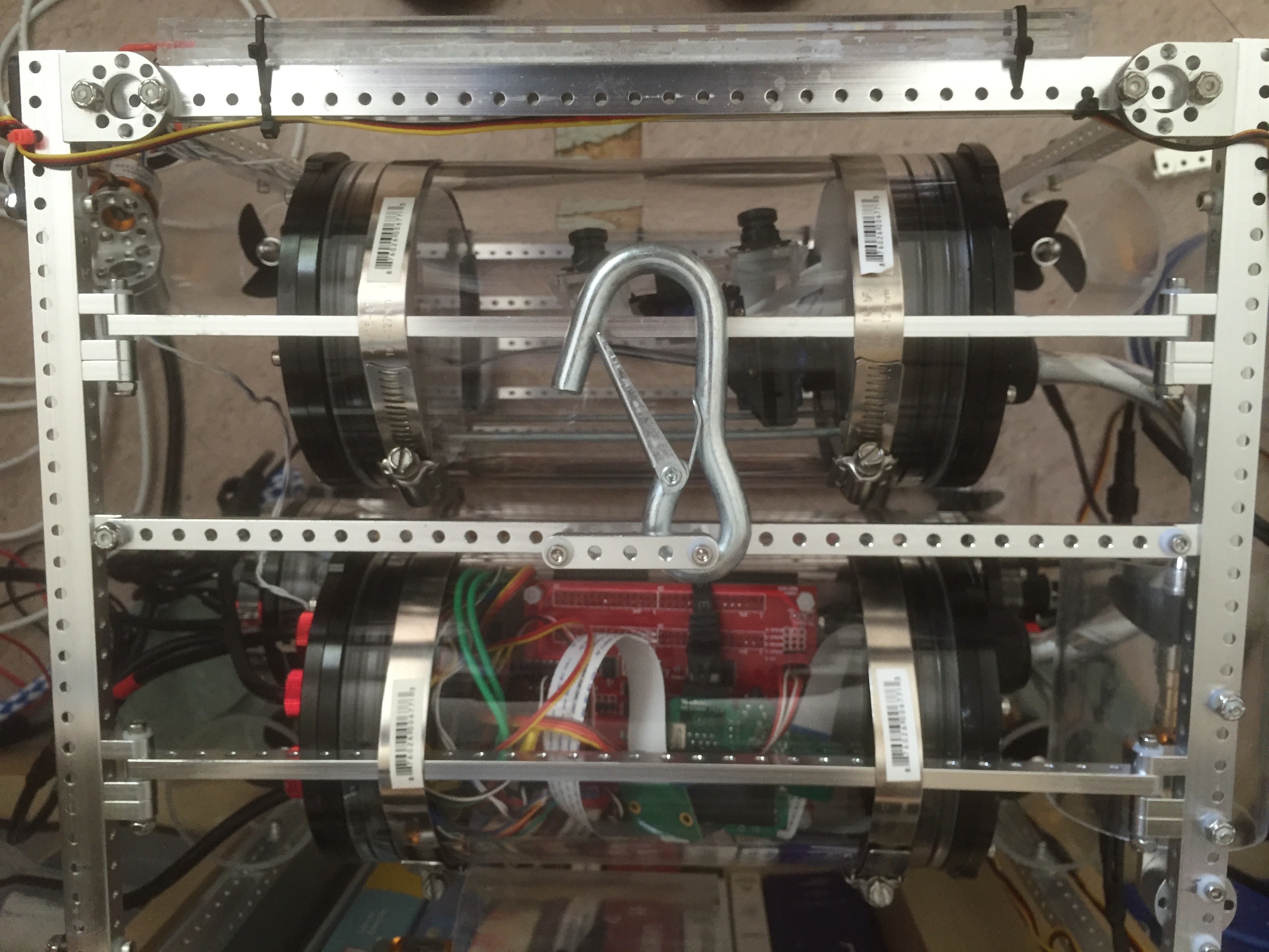
You can see the tubes below, both before and after install. I've also removed one of the 1 pound lead weights in anticipation of re-adjustting the buoyancy - once I finally get it back in the pool.
![]()
![]()
One of the nice side effects of reducing the tube size is that I can now fit the top thrusters inside the cubic frame rather than having them perched on the top (you can just see one of them on the right/middle). I much prefer the ascetics of this, and it also makes the top surface far less fragile.
-
New ESC board integration and testing
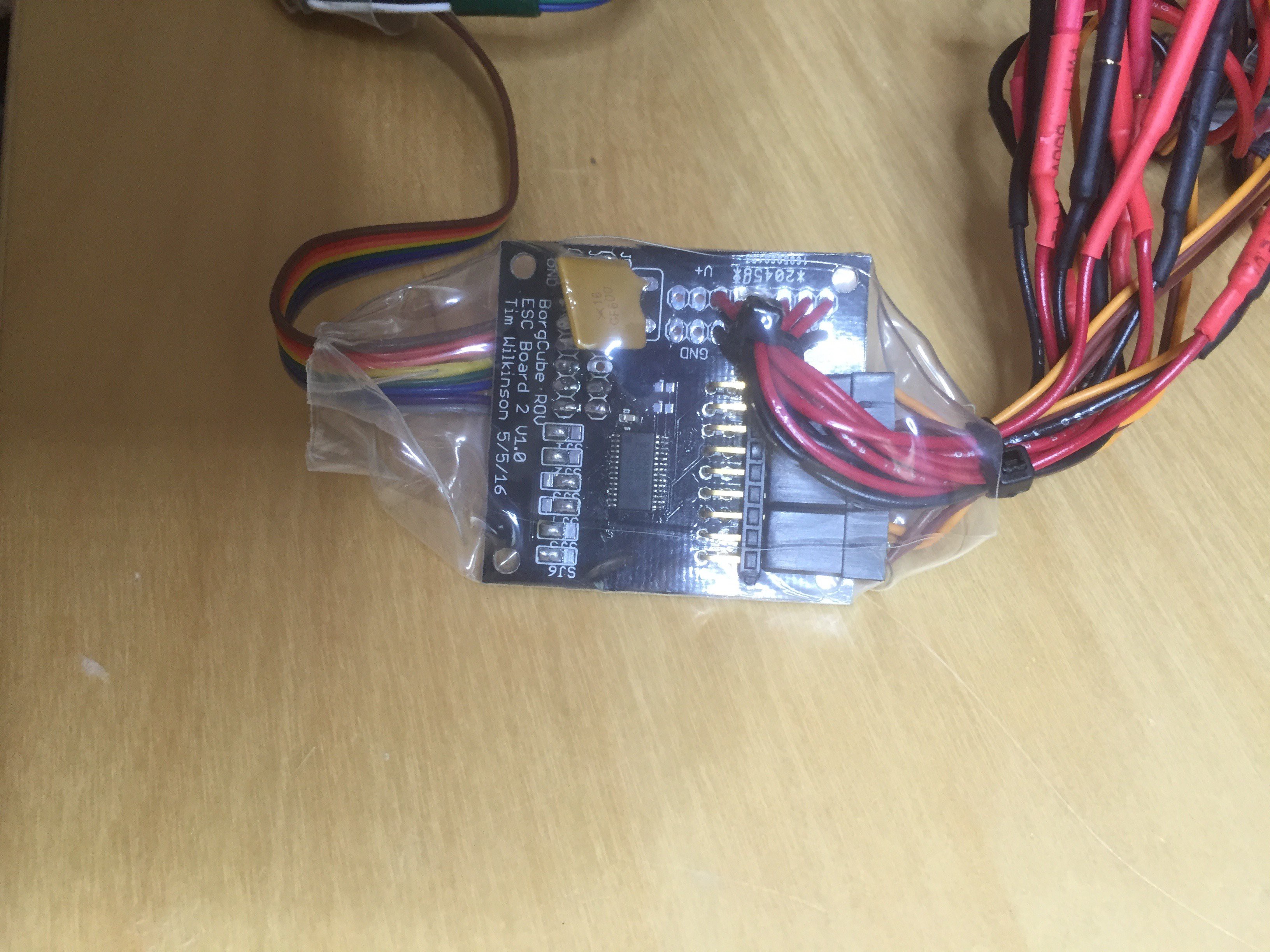
06/01/2016 at 18:04 • 0 commentsThe ESC boards were integrated with the rest of the ROV yesterday. I had originally intended to mount two of the ESC boards onto a piece of acrylic to keep them separate from the batteries which share the same waterproof compartment. Unfortunately this proved too difficult to fit into the enclosure. Instead, I've wrapped each fully populated ESC board in shrink-wrap which allows their placement in the enclosure to be a little more "free form".
![]()
The shrink-wrap simply keeps all the electronics safe.
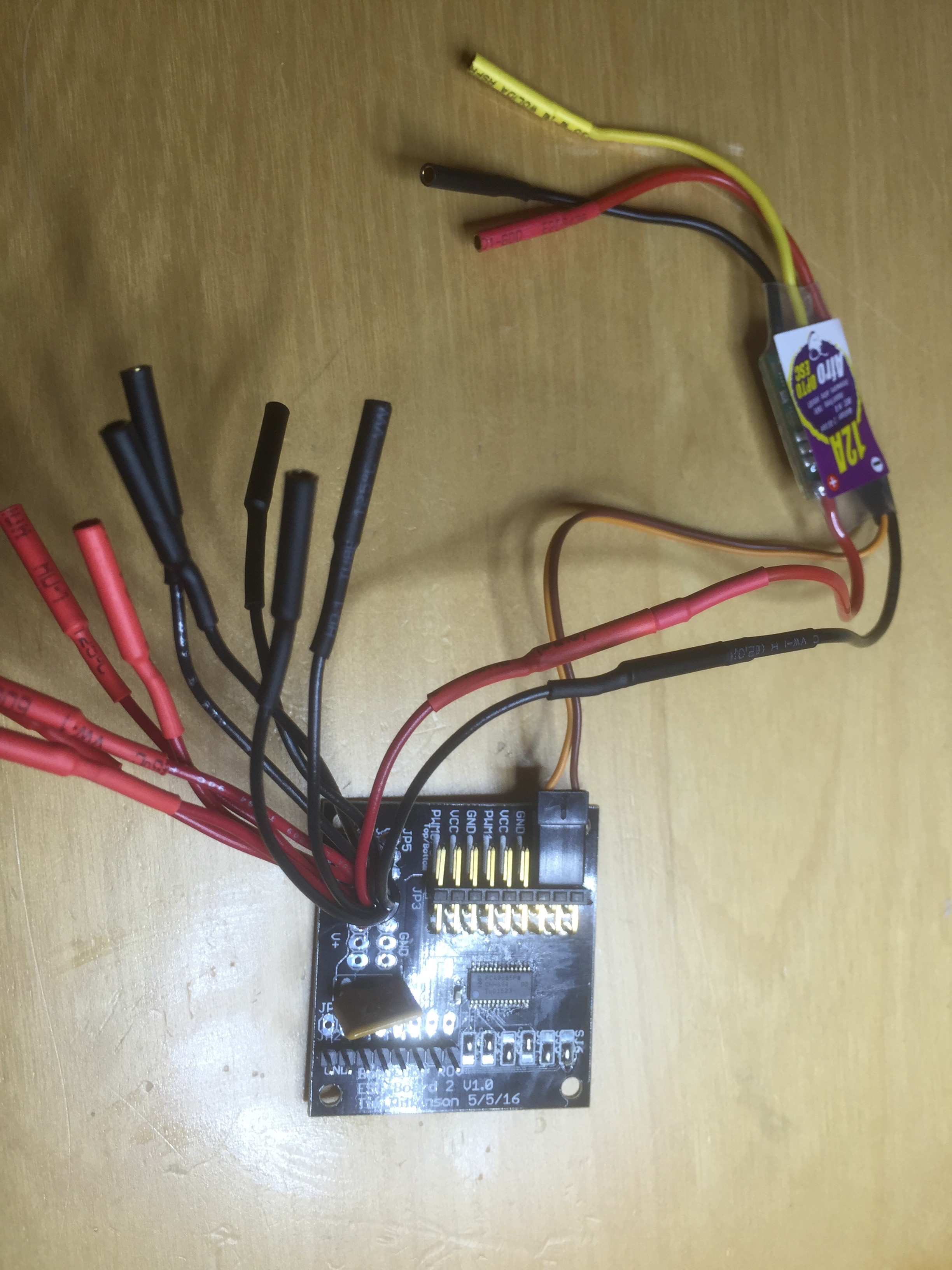
Because the ESCs are now split between two PWM controllers (the old ESC control system used one) the pilot code was changed to configure a specific PWM source for each thruster. Also the thrusters are now controlled using Afro Opto 12A ESCs (reprogrammed using the OpenROV SimonK code) rather than the original HobbyKing branded controllers. These ESCs appear to be less fussy about what voltages they'll operate with.
The final result is the power tube is now stuffed with batteries, with 6 ESCs at each end. On dry land everything is working - now back go the pool.
-
Robot Arms
05/18/2016 at 20:58 • 0 commentsWhile waiting for the various bits of the new ESC modules to turn up, I've returned to working on the robot arm/grabber for the ROV. I've been tinkering with various control methods and finally settled on using an identical robot arm but with servos which provide position data rather than acting as servos. Then, in order to get this information into the ROV software, I've used a Teensy LC board to emulate a joystick. The result is a robot arm controller which looks like a joystick to my laptop, and looks like a GamePad to the web APIs.
I've begun the write up here: https://hackaday.io/project/11770-robot-arm-controller for anyone interested.
-
New ESC driver board
05/15/2016 at 07:00 • 0 commentsThe new ESC board turned up in the mail the other day, and I had chance to populate one for testing. Each board drives 6 ESCs (I'll use two in the ROV) using the same PWM control chip as I've used before. I've also added a polyfuse for protection, and added barrel connectors which allow the Afro ESCs to plug easily into this board without modification.
![]()
-
Protection
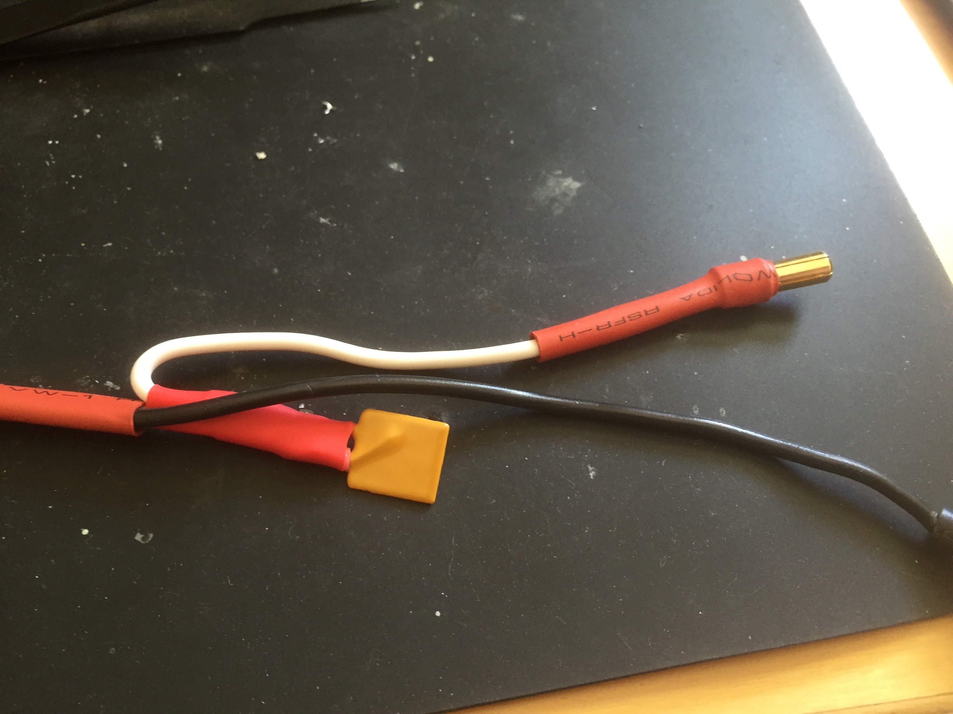
05/08/2016 at 23:32 • 0 commentsAfter my little disaster where a blown ESC took out the entire ESC board and the current resistor on the main daughter board, I've decided a bit of protection might be in order (better late than never I suppose). So, as well as the polyfuses on the new ESC board, I've added a polyfuse between the battery and everything else. You can see it inserted into the V+ line below.
![]()
-
ESC - Version 2
05/06/2016 at 05:02 • 0 commentsSo after dismantling the old, slightly burned-out, ESC board, I've decided to abandon this specific ESC approach and put all the ESCs into a water tight vessel just like the rest of the electronics (i.e. option 2). When I was originally designing the ESC system I'd imagined I'd be providing power from the surface. However, when that was demonstrated to be impractical, I added an additional water tight cylinder in which I put the batteries. There's quite a bit of extra space inside this tube, and if i switch the endcaps for ones with more penetrators, I can bring out all the ESCs.
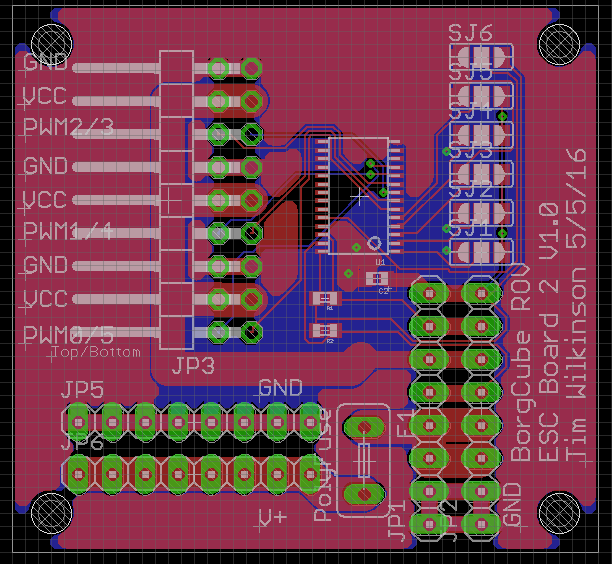
However, I do need to build a new ESC power board since that design is essentially the same. So I can feed ESCs out of both ends of the tube (with batteries in the middle) I designed a simple PWM board for 6 ESCs and will place two board in the cylinder. The Eagle version of the board is below.
![]()
To be honest, this isn't much different from the Adafruit PWM board I often use in testing. But this board is setup for my bus design and has specific places to solder the ESC power cables. I also threw in a spot for a polyfuse, which would have been a very good idea the first time round.
-
More Damage :-(
05/04/2016 at 21:21 • 0 commentsAfter fixing the main PCB last night I had chance to check the rest of the ROV this morning .... and I found the source of the current surge which fried the current resistor.
![]()
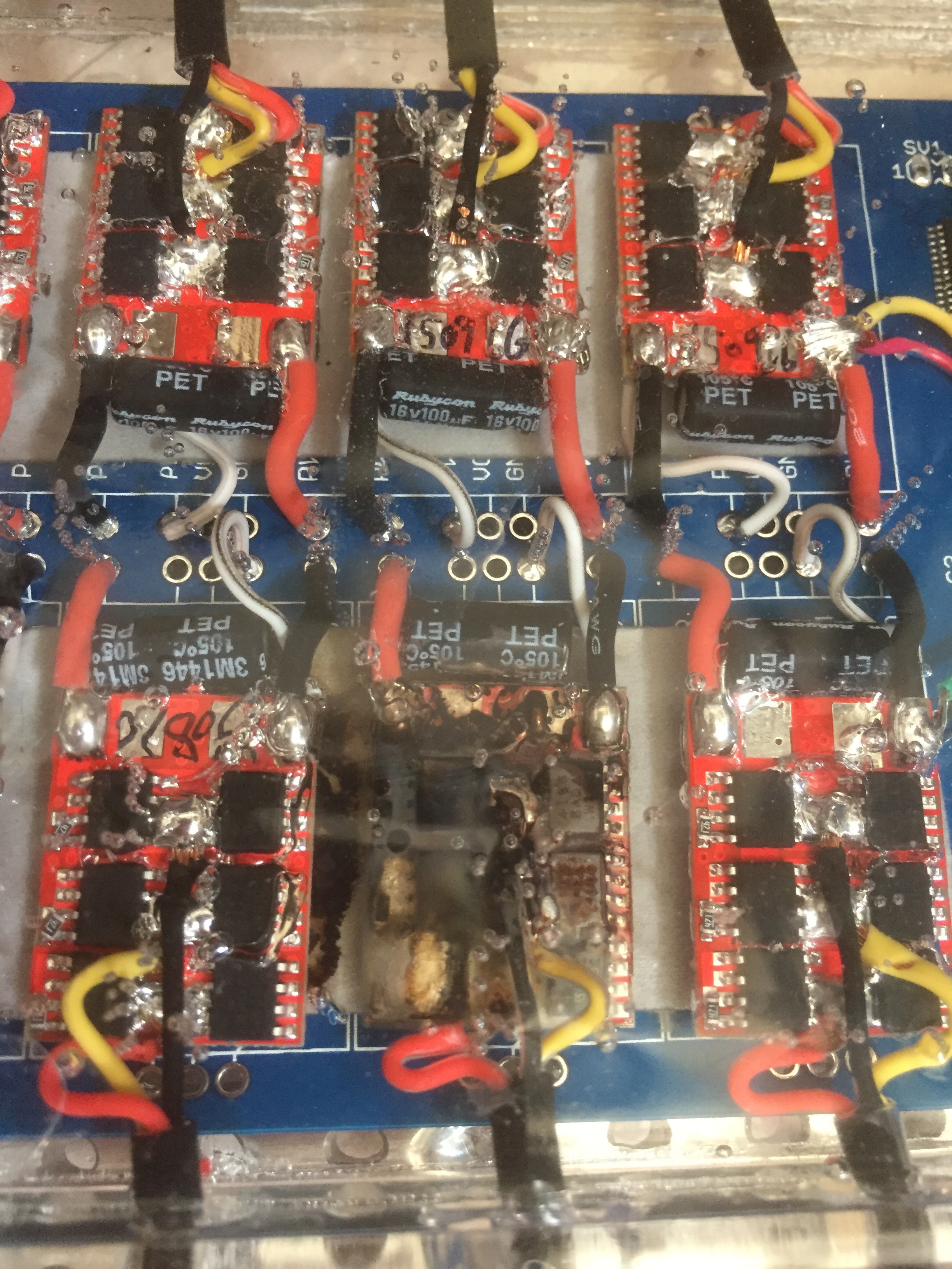
One of these ESCs is not like the others :-( These are all encased in QSil which means I needed to dig it out. Here it is ... doesn't look good does it.
![]()
So what happened? It's difficult to say for sure; ESCs can fail for many reason, including them being cheap and it's what you should expect occasionally. But I'm inclined to think the failure was caused by water. Although the entire board of ESCs is sealer in QSil, examining all the others carefully you can see a hazy grayness around some of the power wires going to the motors; almost as if there's a small air gap forming. I think what's probably happening is that, as the wire warms, the bond between it and the QSill is being broken, and water is getting in. Once the water makes it all the way to the ESC ... KABOOM!!
Rather annoyingly, this means I need to completely rebuild my ESC board. I have two obvious options - (1) reseal the ESCs in something more effective at keeping the water out, or (2) build a different kind of ESC enclosure. Right now, not sure which is best.
-
Things go BANG!
05/04/2016 at 05:29 • 0 commentsToday I had chance to put the ROV back in the tank and begin work on turning the PID controllers. PID controllers are a software device which are used to manage a closed feedback loop (see Wikipedia for an overview). In this case I'm using them to manage the thrusters, and the first ones I'm working on are the pitch and roll stabilizers. The goal is to keep the craft stable in the water regardless of changes to the ROV's environment.
All was going well for a while, then suddenly all the electronic failed! :-(
I initially suspected that water must have entered one of the enclosures, but once I'd removed it from the tank, I couldn't find any evidence of this. Dragging the ROV back to the workbench and attaching it to the bench power supply, I could see that it was no longer drawing any power. Thinking the power regulator must have failed, I remove the main pcb and was met by the familiar smell of a component that has blown up. It was easy to spot ...
![]()
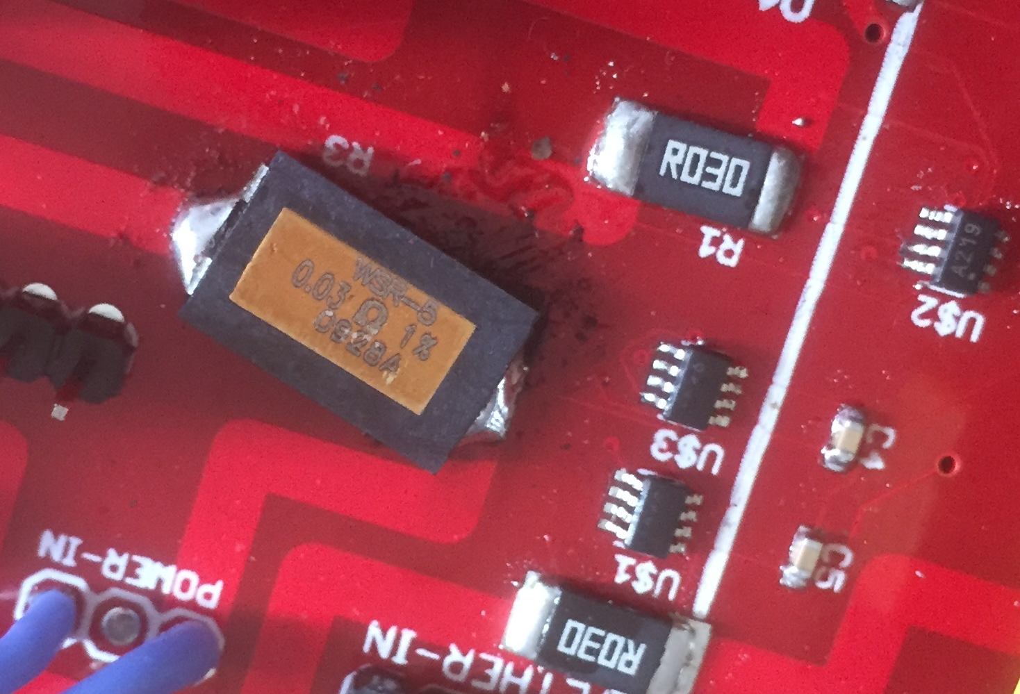
The component is the main current resistor used to measure the power from the batteries. For whatever reason, I'd obviously put too much power through it and blown it up.
The resistor the failed was rated at 3W which I've worried is insufficient for running the motors.
I've patched the board and jury rigged a new resistor in place of the old. This one is rated at 5W and is substantially meatier (compare it to another current resistor above and right)
![]()
We'll see if this works tomorrow.
-
Gamepad
04/12/2016 at 00:56 • 0 commentsLife has been a little busy, so updates have been slow in coming (and most of the work has been in the software which is wait on a long log entry); but more interesting stuff soon. In the meantime I've been looking at what game controller makes sense for controlling the ROV. Since my son had an Xbox 360 controller sitting around I initially thought that might work well - you can certainly make it work on a PC (with a little convincing Windows that is okay really) and on the Mac there's a fantastic project to provide a driver (see https://github.com/360Controller/360Controller). However, both require a USB port and on my MacBook I only have the one which is plugged into the tether box. What to do? After all, while Macs are hardly gaming machines, there must be some sort of gamepad you can get for them ... right? And it turns out that this is true - specifically the PS4 Wireless gamepad controller is a Bluetooth device, will quite happily pair with a Mac, and work just fine.
![]()
On the software side, the gamepad is exposed via a browser API (see https://developer.mozilla.org/en-US/docs/Web/API/Gamepad_API/Using_the_Gamepad_API) just like a mouse of keyboard. It's all suspiciously easy.
 Tim Wilkinson
