Tim Wilkinson
-
First cockpit photos
02/29/2016 at 06:11 • 0 commentsHere are the first cockpit photos:
![]()
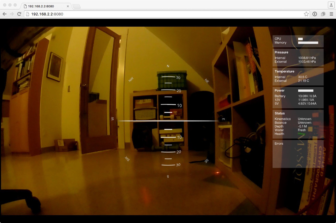
The cockpit is currently in 'mono' mode (i.e. not using the stereo camera system) ... which is kind of obvious since there's only one image. On the right you can see various pieces of information:
- Current CPU and memory utilization
- Internal (inside the air tight hull) and external (the water) pressures
- Internal (inside the hull) and external (the water) temperatures
- Power voltage levels and current current consumption of the 3 voltage sources
- Status of the craft
- Kinematics is the state of the IMU - calibrated when in use
- Balance on/off - the automated balancing system which keeps the craft level and steady
- Depth - the depth of the craft calculated based on the external pressure and the water density
- Water - fresh or salt water environment
- Health - general health of the craft
- Errors displays any error message logged on the craft
The center instrument is the artificial horizon and compass. The artificial horizon (the middle bit) shows the current pitch and roll of the craft. The compass (around the edge) show the direction the craft is facing.
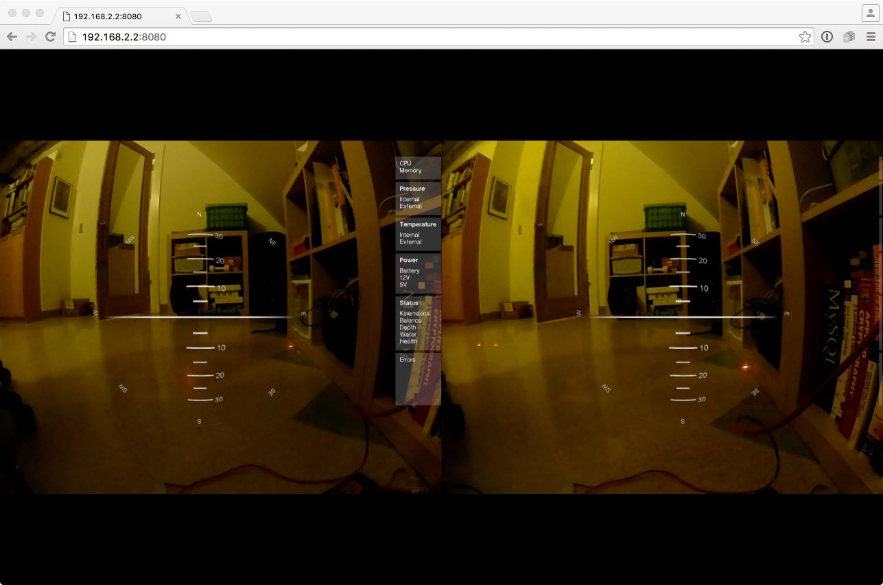
All the instrumentation is built using "three.js", a Javascript based 3d modeling library which runs in the browser. I chose this approach because it allows me to easy switch the 3D mode. You can see that below (although this still needs some tuning because I've not actually plugged in my Rift to check everything):
![]()
In this image two cameras are being used while three.js is duplicating the instruments based on their positions in 3d space.
-
Main Daughter Board: Version 1.1
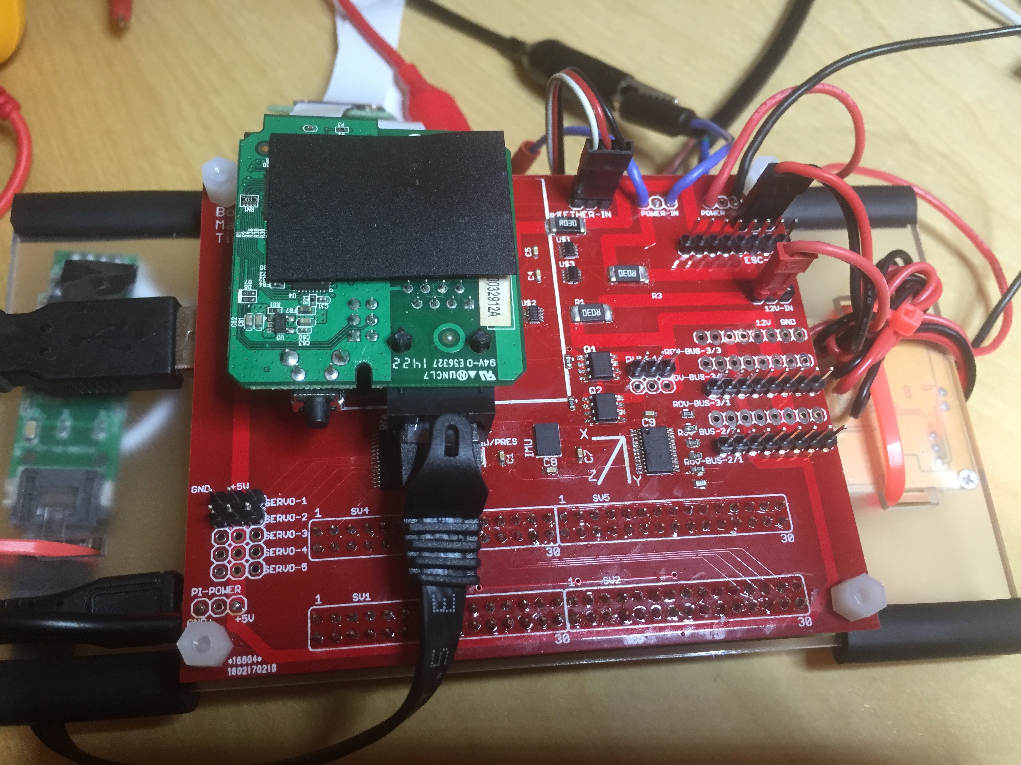
02/27/2016 at 08:35 • 0 commentsVersion 1.1 of the main daughter board arrived a few days ago. I ordered it from DirtyPCBs a while back but due to the Chinese holiday it took a little longer than usual to turn up. The primary goal for V1.1 was to cleanup the various mistakes from V1.0, and also to add an I2C multiplexer chip. This provides two useful functions: 1 - it provides some level of protection to the Raspberry Pi when I'm messing with I2C devices in the ROV, and 2 - it allows me to handle address conflicts by placing I2C devices with the same address on different buses. The V1.0 had an address conflict when I tried to add the water pressure sensor - the address clashed with the humidity/pressure/temp sensor. In V1.1 I moved the latter sensor to it's alternate address, but I wanted to add some extra safety for the future.
The new board, mounted on the Pi with the Tenda board, can be seen below and - amazingly - all seems to work.
![]()
-
Submersion test
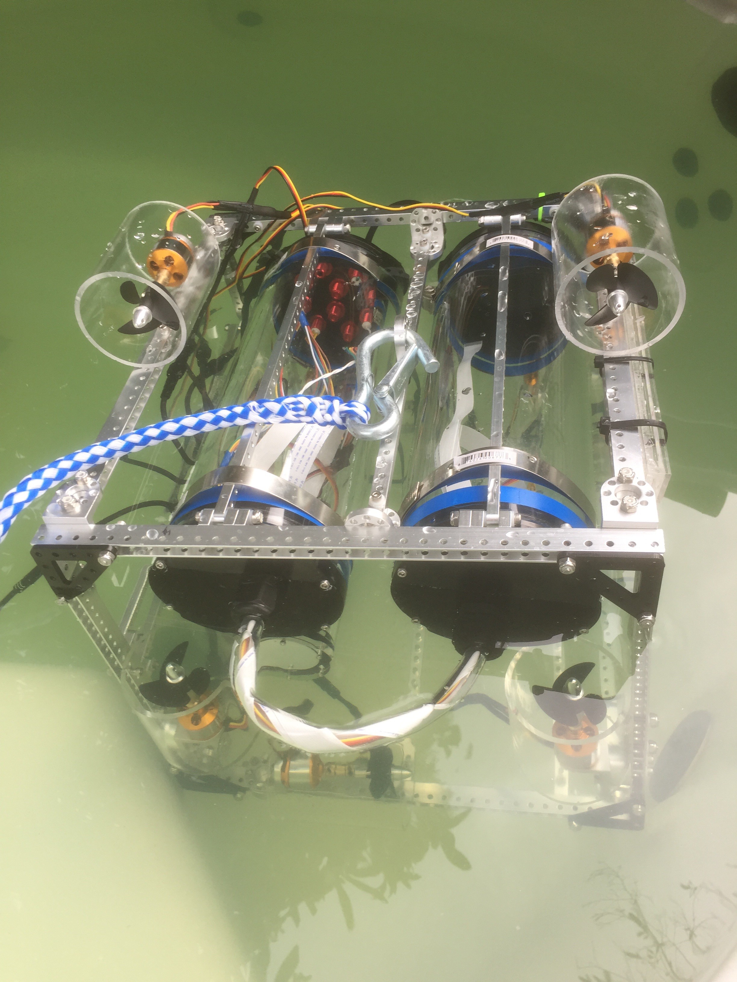
02/23/2016 at 22:22 • 0 commentsLast week I finally did the first submersion test of the frame, motors, and electronics housings. There were no actual electronics on board apart from the potted ESC board. The goal was to see if anything leaked.
![]()
Fortunately I have a hot tub in my back yard, so the test just involved taking off the lids, and popping the frame into the warm water.
First - nothing leaks! I'm ridiculously happy about this. Hardly a pressure test, but a success. Second - when you put closed tubes of air on 100 degree water, the air warms up and threatens to push the tube ends out. Thankfully that didn't happen, and obviously not a problem underwater. Third - I need to clean the hot tub! I don't think it's suppose to be that color.
-
Laser cutting servo mounts
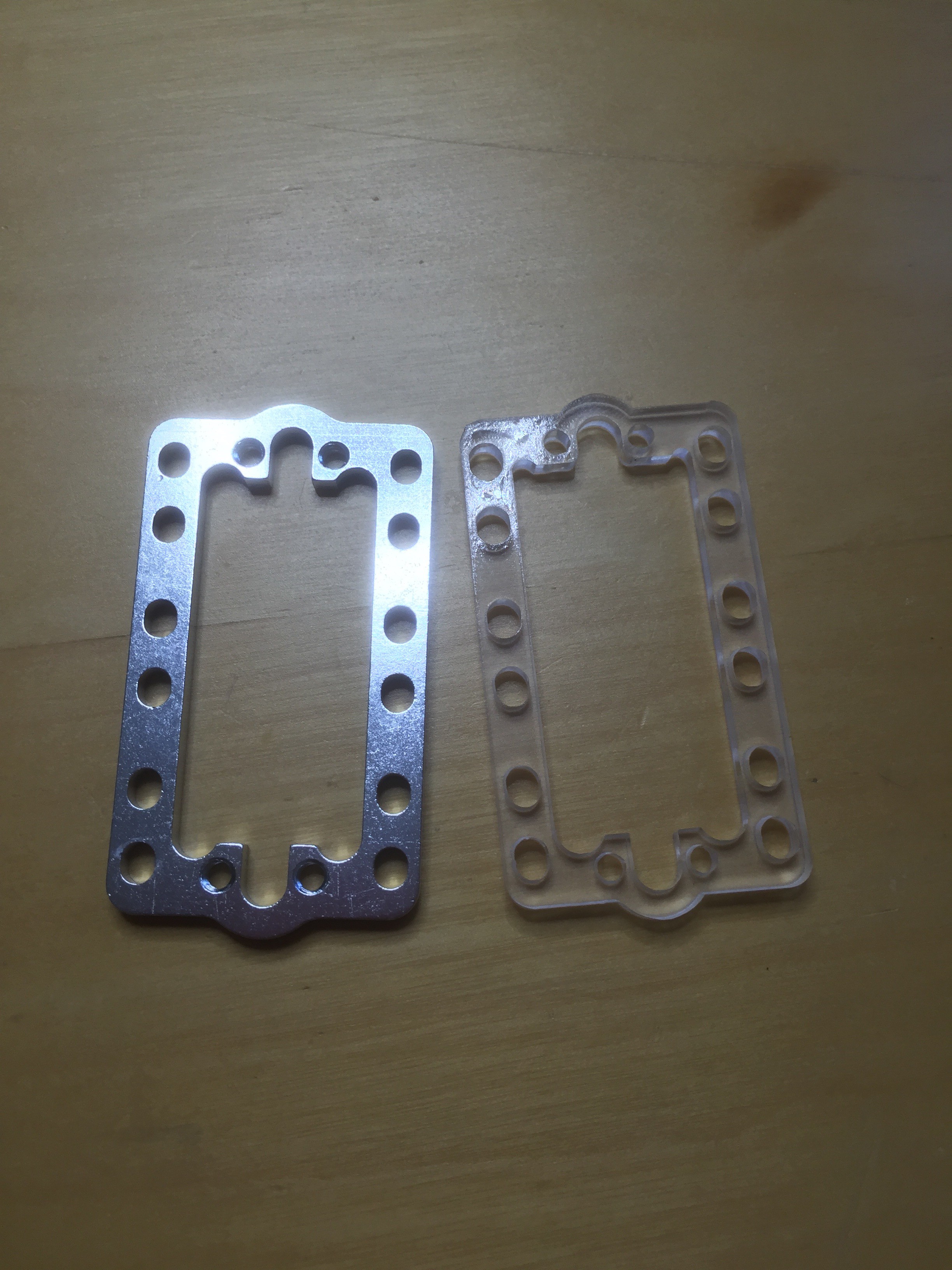
02/12/2016 at 07:46 • 0 commentsI've been bother for some time about how the robot arm is mounted on the ROV. The waterproof servos I'm using a slightly larger than their non-waterproof cousins - only a millimeter perhaps - but enough that none of the standard mounting brackets I have will work. I had originally mounted the arm using some less than ideal pieces of metalwork which were definitely strained in ways that didn't make them or me happy. I wanted to do something better.
Then there other day it struck me what I could simply laser cut a new acrylic mounting bracket - just the same as the one which didn't quite fit - but make it slightly larger so the servo would fit correctly.
![]()
In the photo, the bracket on the left is the original, while the acrylic bracket on the right is the laser cut alternative. The hole in the center for the servo is slightly longer and wider, but it's otherwise the same. This means I can finally mount the robot arm servo to the ROV frame "properly".
-
Topside tether
02/04/2016 at 03:33 • 0 commentsHaving decided that the ROV will have its own power and not be powered by the tether, I finally built a prototype topside tether. The purpose of this is to take the homeplug signal, convert it to ethernet, and connect it to my laptop. As it happens, my laptop doesn't have an ethernet connector, so I'll also need a USB-to-Ethernet converter. And this made me thing that perhaps I should just put that converter into my topside tether also. The result looks like this:
The USB hub+ethernet plugs into the laptop, and the ethernet connects to the homeplug box. I also added a USB powered 5v-to-3.3v buck converter to power the homeplug board from USB. The result is a simple one-cable topside tether. Now I need to mount this all.![]()
Update: Mounted
![]()
-
Hitec servo teardown
02/03/2016 at 20:20 • 0 commentsSomeone over on RC Crawler took a hitec waterproof servo to pieces and it looks promising given how it's constructed. Maybe it'll survive better than I expected.
http://www.rccrawler.com/forum/electronics/368223-hitec-5646wp-servo-winch.html
-
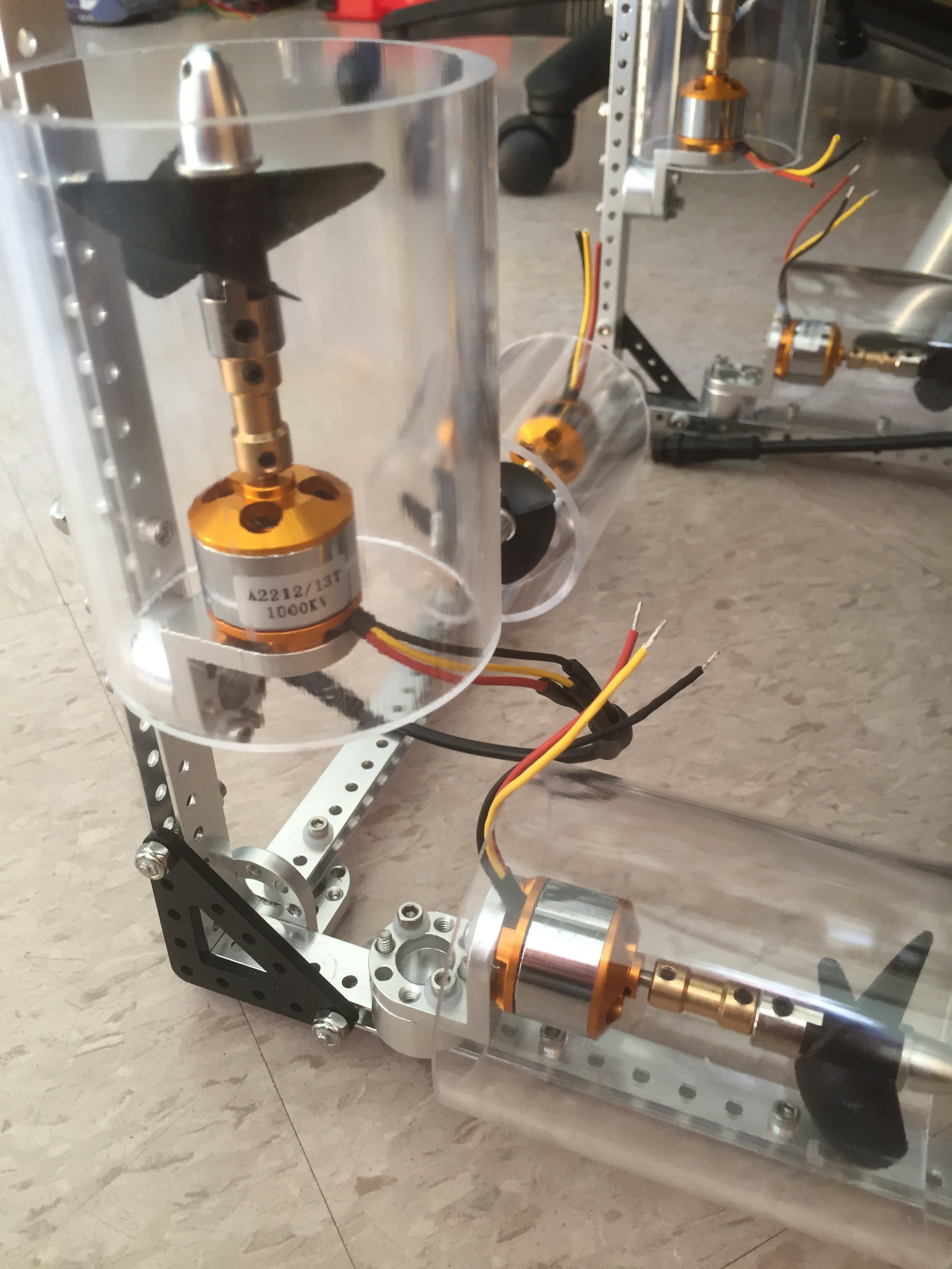
Thruster casing
02/02/2016 at 23:18 • 0 commentsWhile I'm basically okay with the thrusters being exposed on the ROV, I think it's probably better for my own fingers if I put some kind of protection between the whirling propellers and me. So I had Tap Plastics cut me 12 pieces of 3.5" long, 2.5" ID, acrylic tubing which fits around the thrusters, with a little room to spare. I made mounting holes in the tubes using a laser cutter. The results can be seen below:
![]()
Not sure how this will effect the thruster efficiency; either positively or negatively.
-
Alternative power arrangements
01/31/2016 at 06:21 • 0 commentsGiven the latest set back at providing power to the ESCs, I'm beginning to reconsider the current power strategy.
I've been looking at my tether solution and doing the math on how that will effect my "power from the surface" approach. My tether is currently 200ft of 22AWG mil-spec wire. This has a total resistance of 6 ohms. I'd planned to use a large 4S LiPo as the power source, giving me 14.8V. This limits the current to 2.5A ... assuming I'm okay will all the power being dropped on the tether (err ... no). The power regulator on the ROV can handle 26V, so my first alternative would be to boost the tether voltage to 26V. This limits the current to 4.3A .... again with all the power dropping on the tether. Obviously this isn't going to work for the ESCs, so either I increase the gauge of the tether or increase the voltage further. Increasing the gauge will cause tether buoyancy issues (already a concern), while increasing the voltage introduces safety issues (this is in water after all).
So, time to investigate putting batteries in the ROV.
-
ESC power problems
01/30/2016 at 08:03 • 0 commentsToday I hooked up the ESCs to the real power supply (rather than the bench supply) and the motors fail to start - in fact the ESC will often reboot itself. What gives? Well, it looks like the instantaneous power requirements for starting a motor cannot be met by the BEC I chose. I tried adding some big capacitors to see if that would help with startup, but no luck. So back to the drawing board on supplying 12V. I'll try a 10A buck converter and see if that solves the problem.
Update 1/30/16
So I checked the inrush current of the motors (the instantaneous current required when the motor starts moving) and it appears to be 3.5A. Obviously a bit too close to the 4A BEC limit.
-
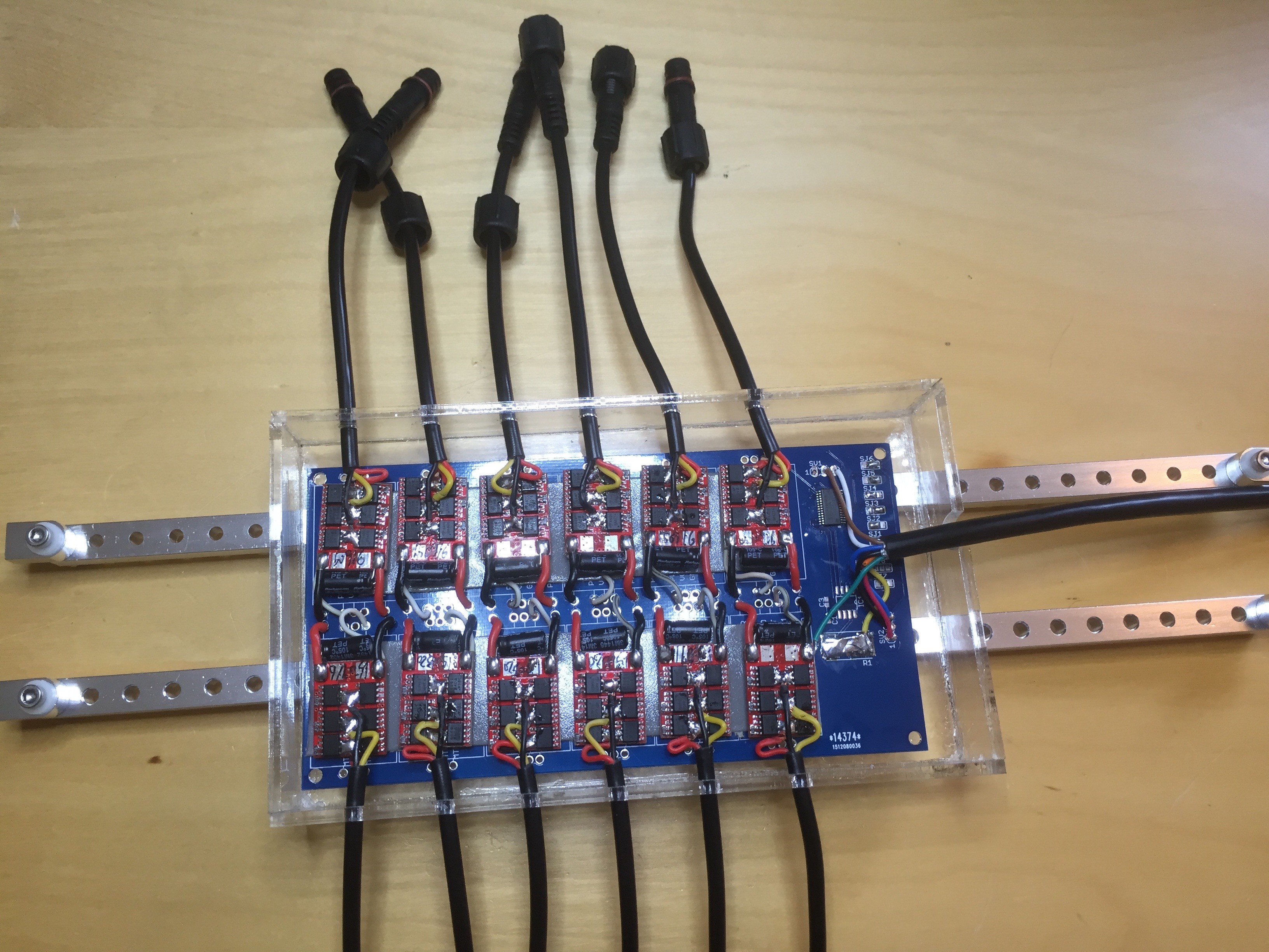
ESC housing
01/29/2016 at 01:50 • 0 commentsI build the 12-ESC board a while ago, and have been waiting on Ali Express to deliver the connector cables. Well, finally the arrived and I was able to laser cut the acrylic housing I'll use to pot the ESC board. The assembled board, in it's housing and support structure, with the connectors is shown below:
![]()
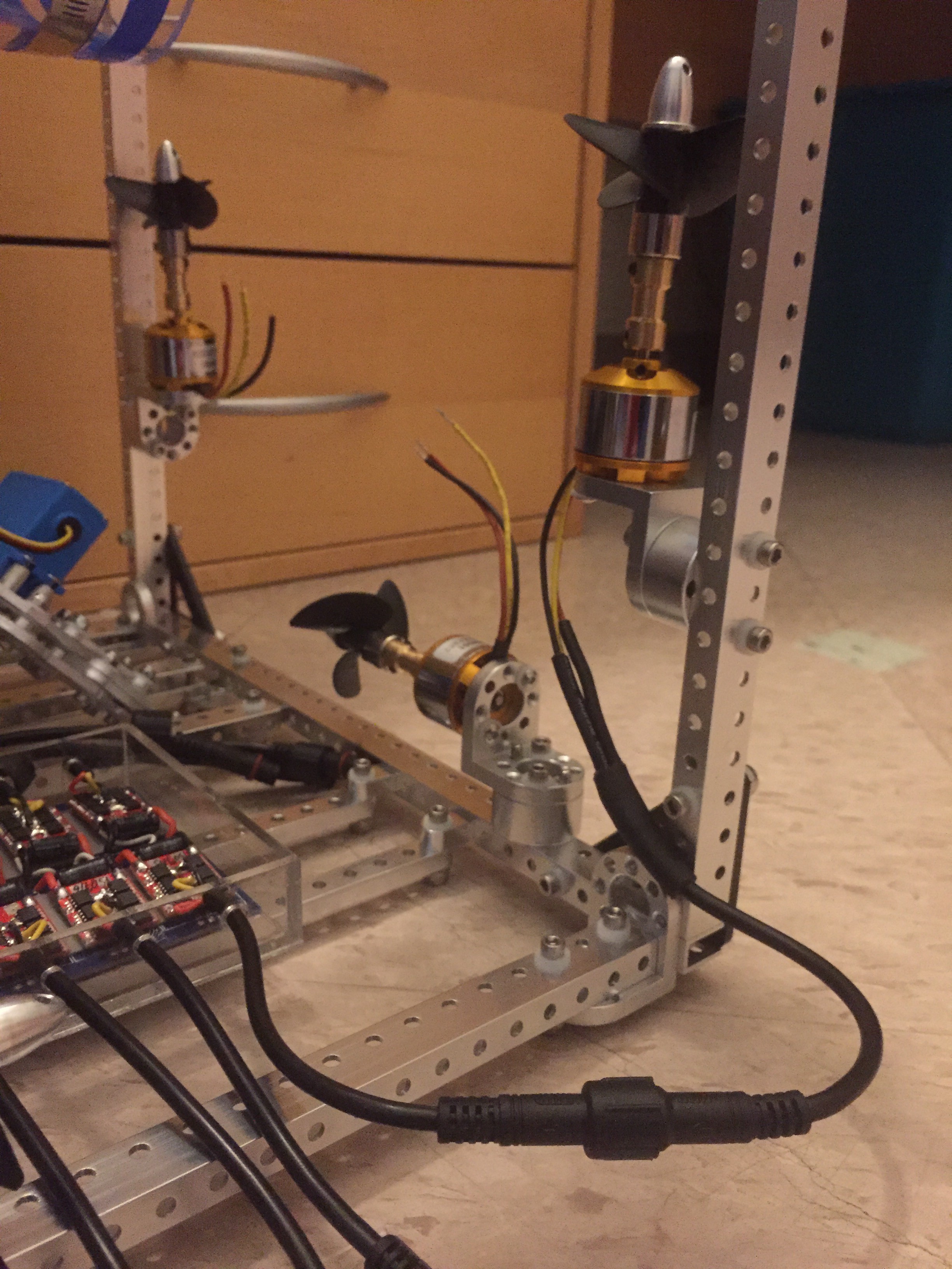
The top and bottom connectors attach the ESCs to their respective motors. The right connector is the ROV bus and will attach to the main pressure vessel. Later this box will be filled with QSil to keep the electronics safe.
The female connectors plug into the male connectors attached to the thrusters mounted on the frame. All the wires are connected using marine grade heat shrink. Again, the goal is to keep this modular and allow me to switch and replace pieces.
![]()