Tim Wilkinson
-
Robot Arm: The electronics
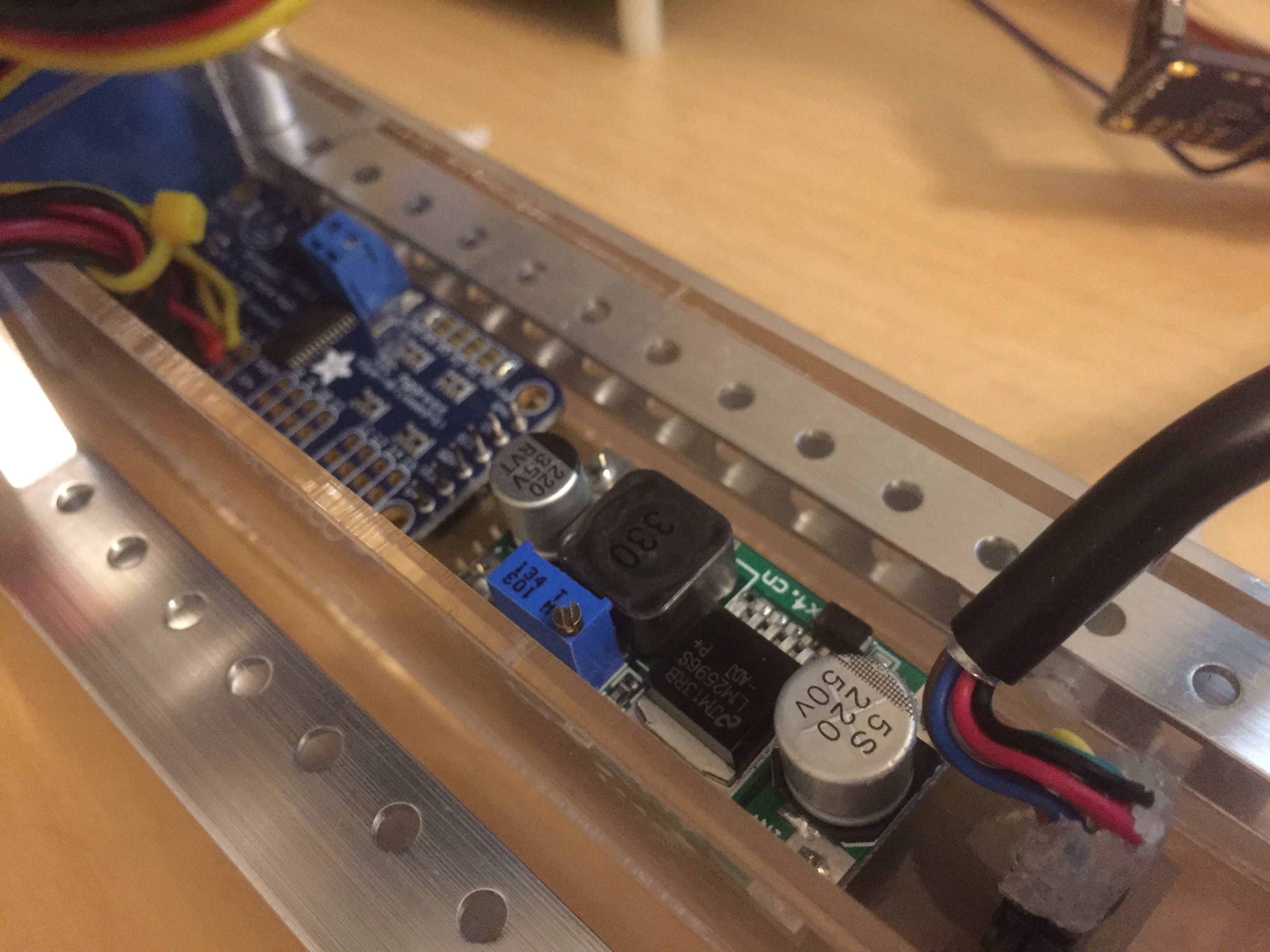
01/13/2016 at 05:50 • 0 commentsThe robot arm consists of a bunch of aluminum brackets, bolts, and 6 servos. As with all servos, these are managed using a pulse-width control scheme (PWM). Because the arm is consider a payload for the ROV, it should operate using the payload bus connector (see a previous post about the "bus"). To make this happen, a little electronics is necessary to convert the I2C payload bus to a set of PWM signals, and also convert the 12V bus "mains" to the 7.4V needed by the servos.
Rather than build a custom board for this, I used two boards I had around the workshop. The first is a I2C PWM board from Adafruit. This allows me to control the servos using I2C. The second is a buck converter from eBay which converts the 12V down to 7.4V. To keep the mounting tidy, I used my PCB router to make a simple inter-connect board, and then mounted the two main boards to that.
![]()
In the above photo, you can see both the two main boards, together with the incoming ROV-BUS connector (bottom right) as well as the servo wiring (top left).
This board is mounted inside a custom cut acrylic box. The box is, in turn, attached to the ROV frame using two nylon bolts. This allows the entire payload to be detached if necessary. To keep the boards water-free, I will eventually pot these components.
-
The Bus: I2C
01/13/2016 at 05:22 • 0 commentsThe core for my ROV include the following:
- Thrusters
- Vision
- Lights
- Communications
- Brain
But I also wanted to be able to add payloads. The core systems in the ROV are being mounted in the two pressurized tubes at the top of the ROV. This leaves the lower part of the ROV for payloads. The first payload will be the manipulator. But ... how best to communicate between payloads and the core? The traditional way to do this would be with a "bus" - a common set of wires and protocols to allow various devices to be attached without knowing what they are before hand. If this were a PC I might be tempted to use USB, but that's a bit heavyweight for the moment. For me, the obvious alternative is to use the I2C bus as a basis. This gives me a well supported communications system and it is implemented by many devices and sensors. But communications is only part of what I need. I also want to be able to provide power to these payloads. I'm planning on providing 3 voltages levels in the ROV - 3.3V, 5V and 12V - and passing these to the payloads too.
![]()
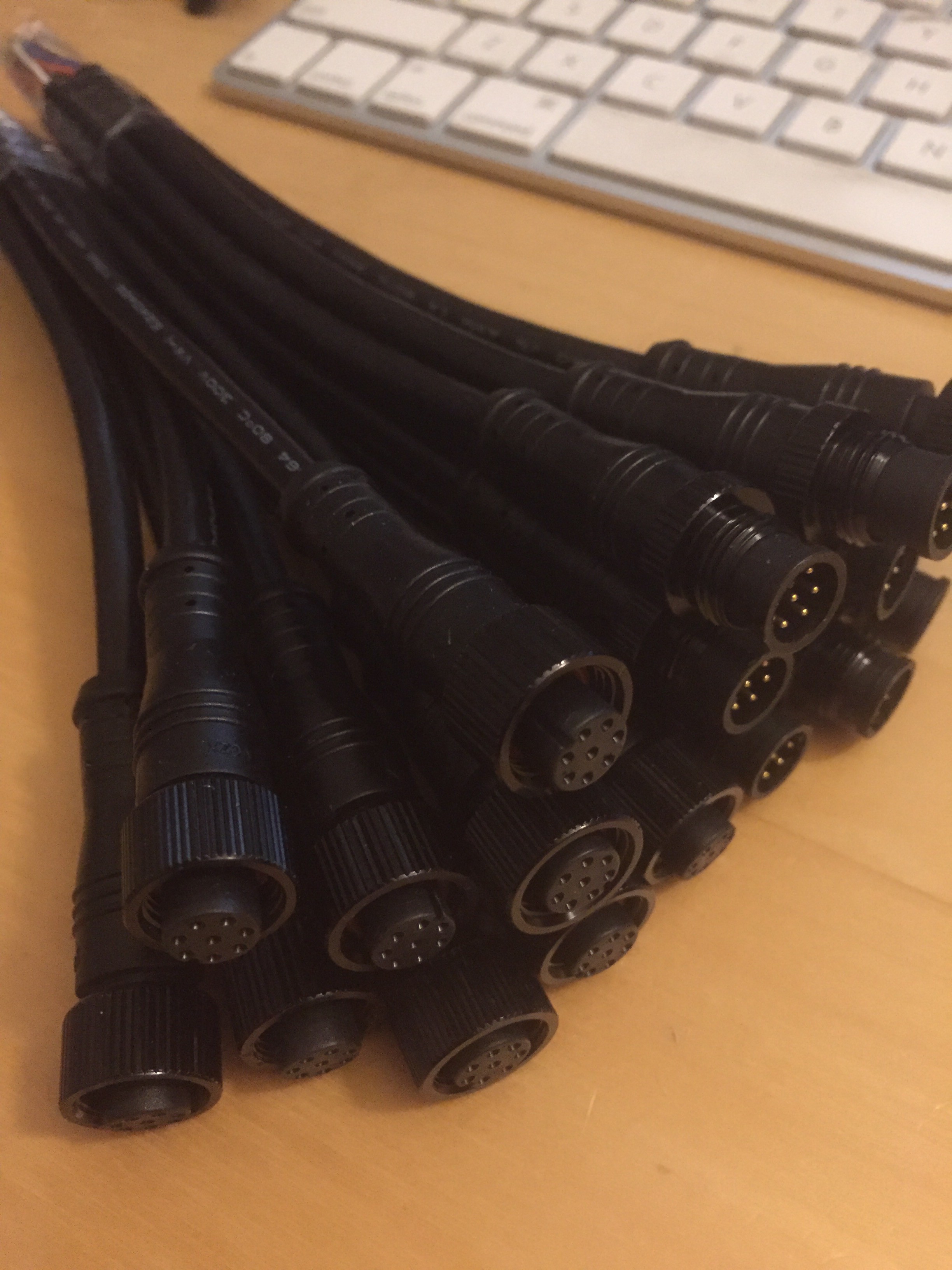
The photo above shows the bus connectors I've choses. These are IP68 rated with 8-cores. I'm using 2 cores for GND, 2 for 12V (the "mains") and one each for 3.3V, 5V, SCL and SDA. Each payload will have a male connector, while the core will provide a number of females.
-
Robot Arm
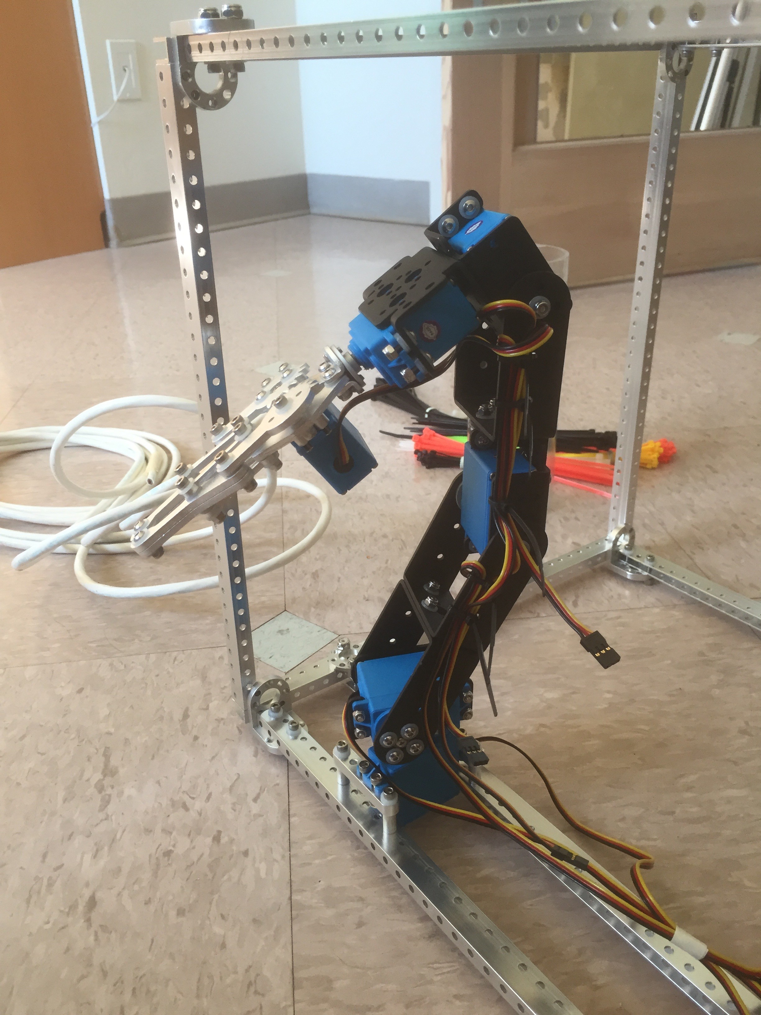
01/10/2016 at 07:39 • 0 commentsI could just build an "observation class" ROV ... but where's the fun in that. I want to build an ROV which can prod its environment. To do that I need a robot arm. The easiest way to do that was to buy a basic robot arm kit on eBay, strip it down, and rebuild it with waterproof servos. Now, these servos are not rated to go very deep and this arm may fail spectacularly .... but it's a place to start .... so ....
I bought the kit here, and followed the instructions here. I stripped out all the steel parts and replaced them with stainless steel, stripped down the grabber and rebuilt that with nylon washers (which greatly improved the smoothness). The assembled kit, mounted to the frame, is shown below:
![]()
-
Camera mount: Update
01/10/2016 at 07:23 • 0 commentsSo made a few changes to the final camera mount. The front chamber is now firmly attached to the frame using an aluminum beam rather than the original suspended using wires. It turned out that these wires couldn't support the unequal weight of the chamber and keep the chamber parallel with the rest of the frame. While this unequal weight should be resolved when I finally add the second endcap, I decided a more rigid attachment system would be better.
![]()
In the photo you can see the final attachment of the two video cables which feed the stereo cameras back to the Raspberry Pi.
-
Camera mount
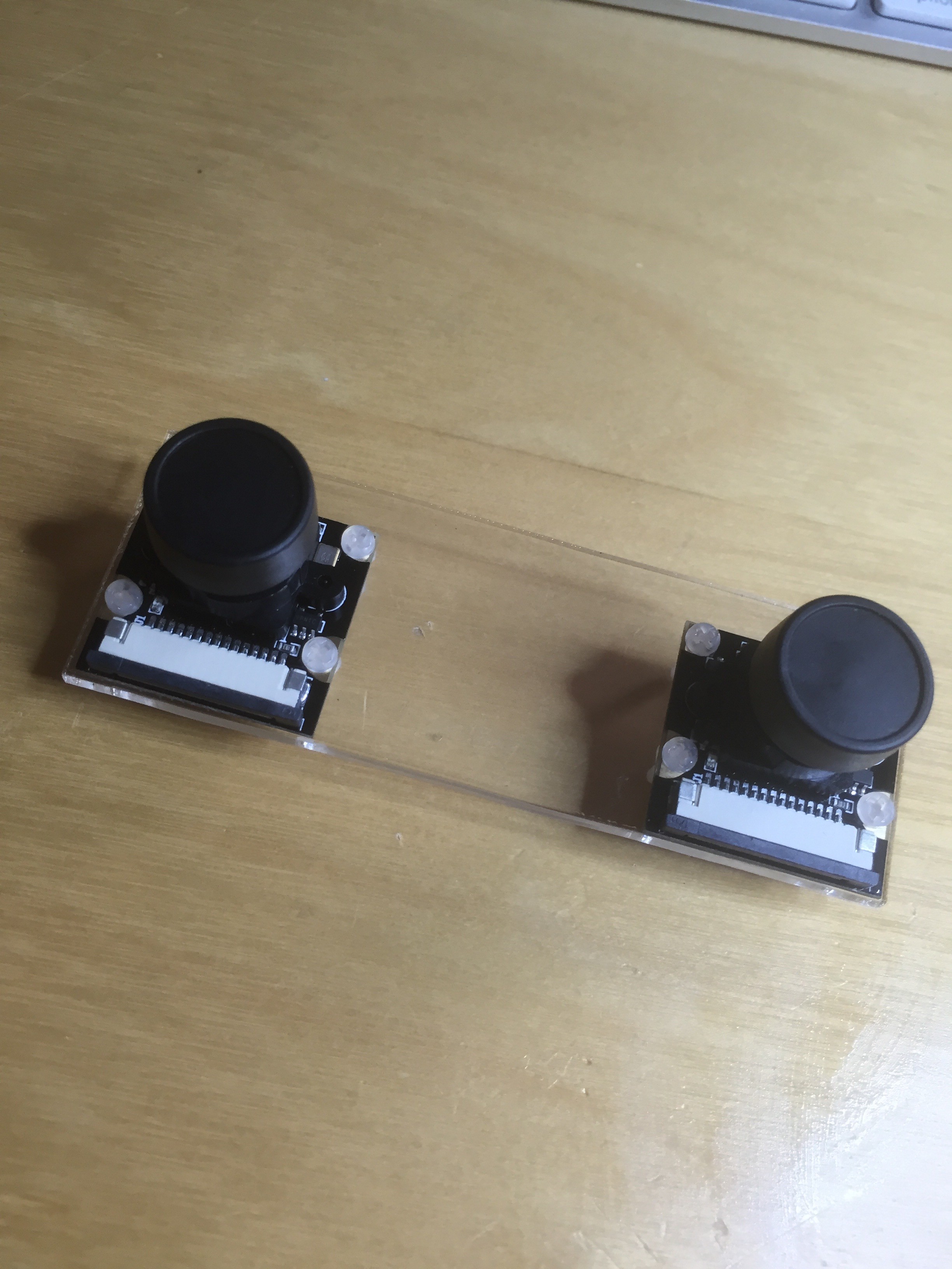
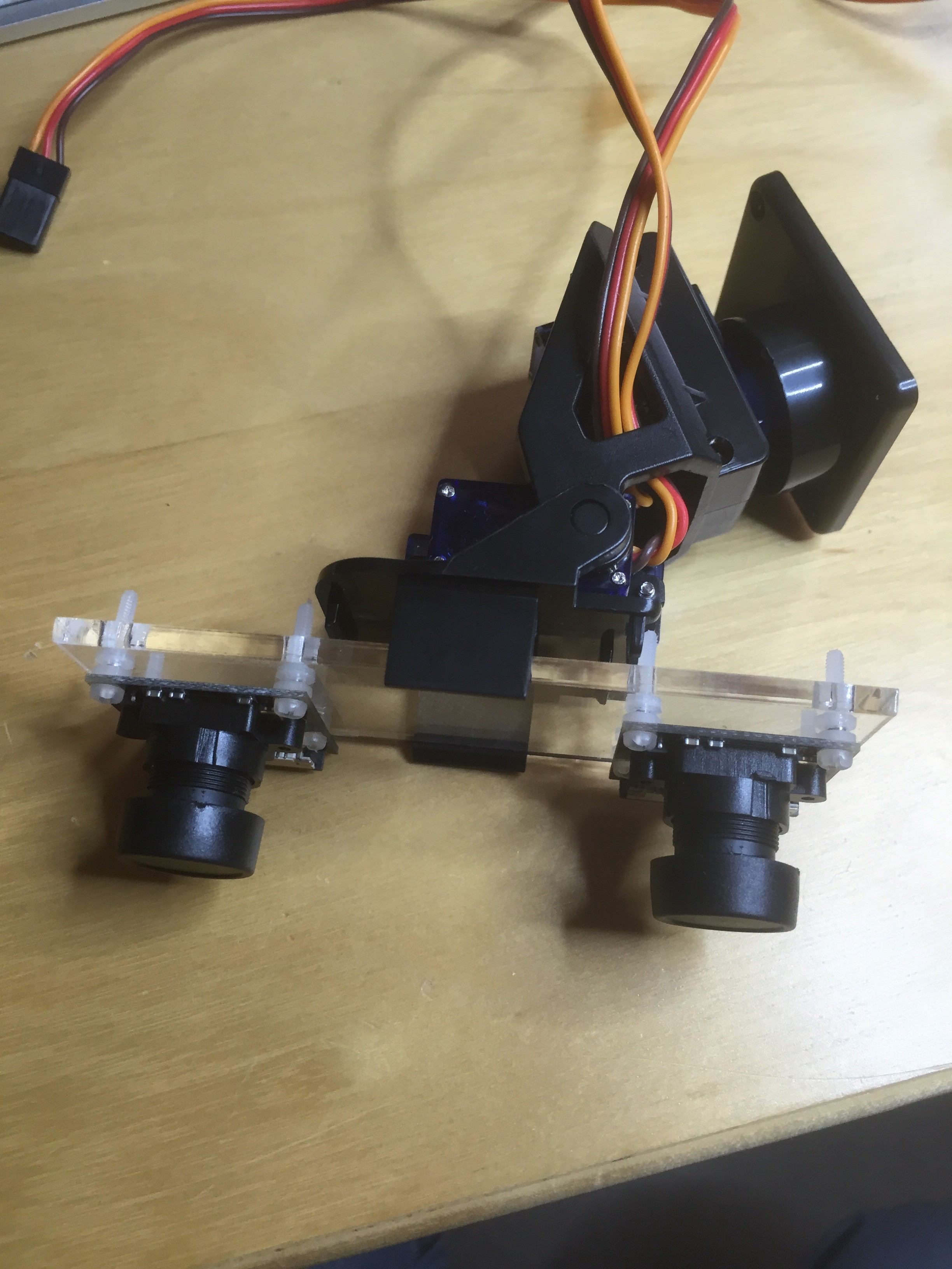
12/23/2015 at 07:08 • 0 commentsThe ROV is going to have stereo vision. That means two cameras. I also want to give the vision a bit of flexibility, so that means some sort of gimbal. The two cameras, as discussed before, as PI cameras that use ribbon cables to plug directly into the Raspberry board. The need to be mounted about 60mm apart. The waterproofing is being provided by the front tube; I just need to work out how to mount the cameras on a gimbal, and how to secure the gimbal in the tube.
I picked a cheap gimbal from EBay and added the two cheap SG90 micro servos to get the movement I needed. To mount the cameras I laser-cut some acrylic with mounting holes,
![]()
bolted the cameras to the plate,
![]()
and then clipped it to the gimbal.
![]()
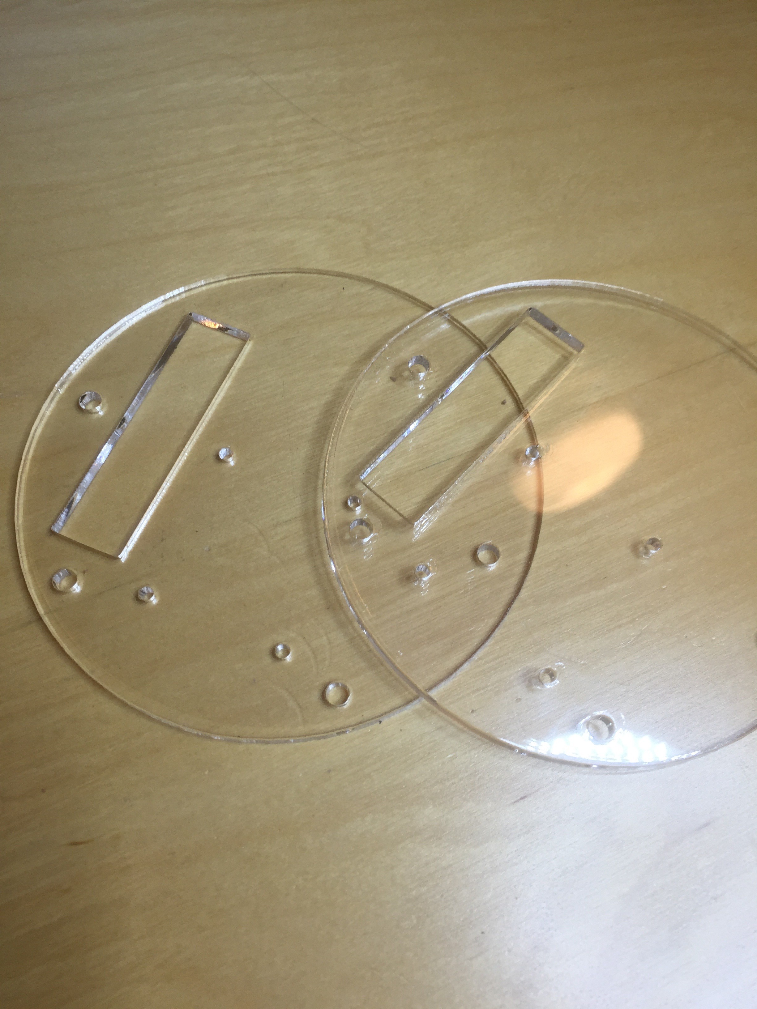
The final problem was how to mount this whole thing in the tube. I didn't want to use glue because I'm sure I'll want to remove and modify things later. However, mounting something on a smooth circular wall wasn't obvious. In the end, I build a harness with two circle acrylic ends,
![]()
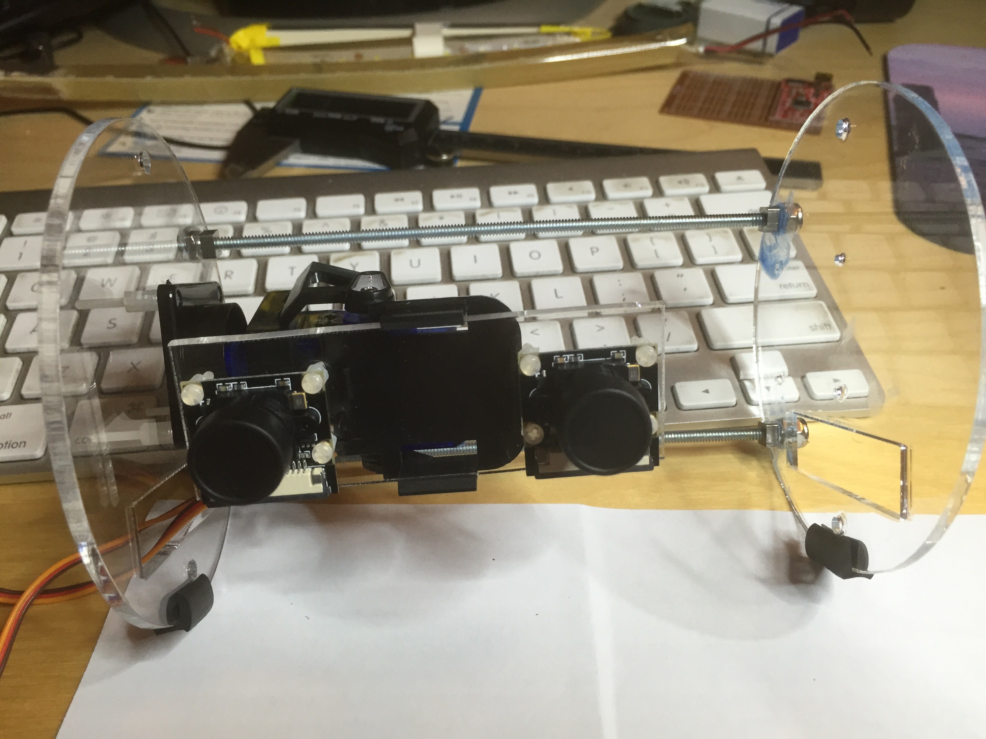
connected using two threaded rods, and secure inside the tube using neoprene edge trim. The resulting assembly looks like this.
![]()
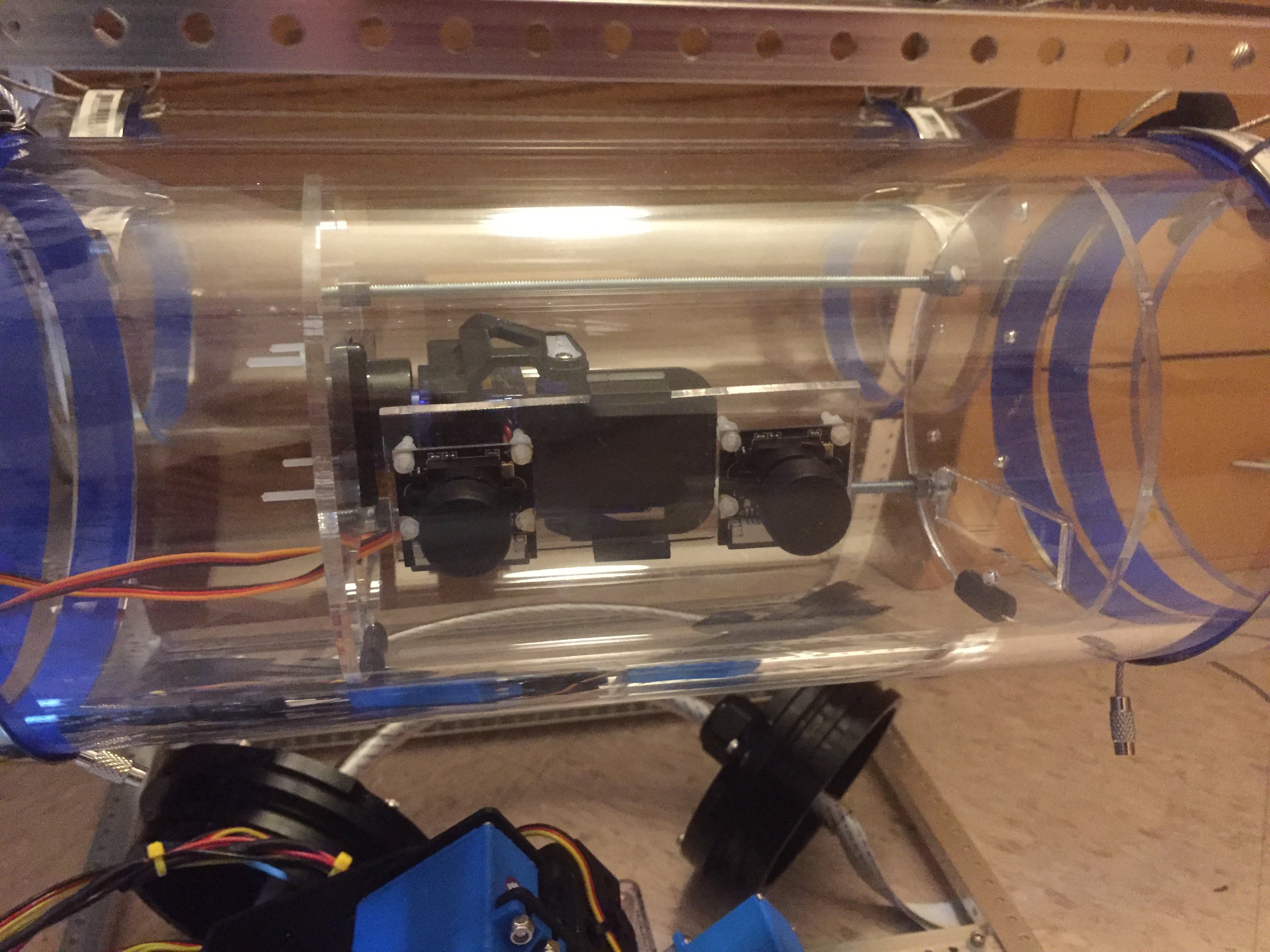
And inside the tube:
![]()
-
Thrusters: ESCs
12/19/2015 at 08:03 • 0 commentsThe ROV will have 12 thrusters. Yes, I realize that's quite a lot and probably overkill, but one of the primary goals is 3D maneuverability. For that I need lots of different thrusters. I don't expect to use them all at once, but it seemed easier to have more thrusters than to provide some mechanism to change the direction of thrust.
When I started investigating options, I was rather surprised to discover that it was possible to run brushless motors in water! At the time I didn't understand what a brushless motor actually was, but after a little research I understand why it works. I'll leave the selection of motors for later and for now just concentrate on the ESC (Electronic Speed Controller). I investigated a few ESCs, including the Turnigy TrackStar 25A Car ESC, the HobbyKing Brushless Car ESC 30A w/ Reverse and the HobbyKing Brushess Car ESC 10A w/ Reverse. I selected the last of these because it (a) worked in my tests, (b) had enough power, and (c) was cheap.
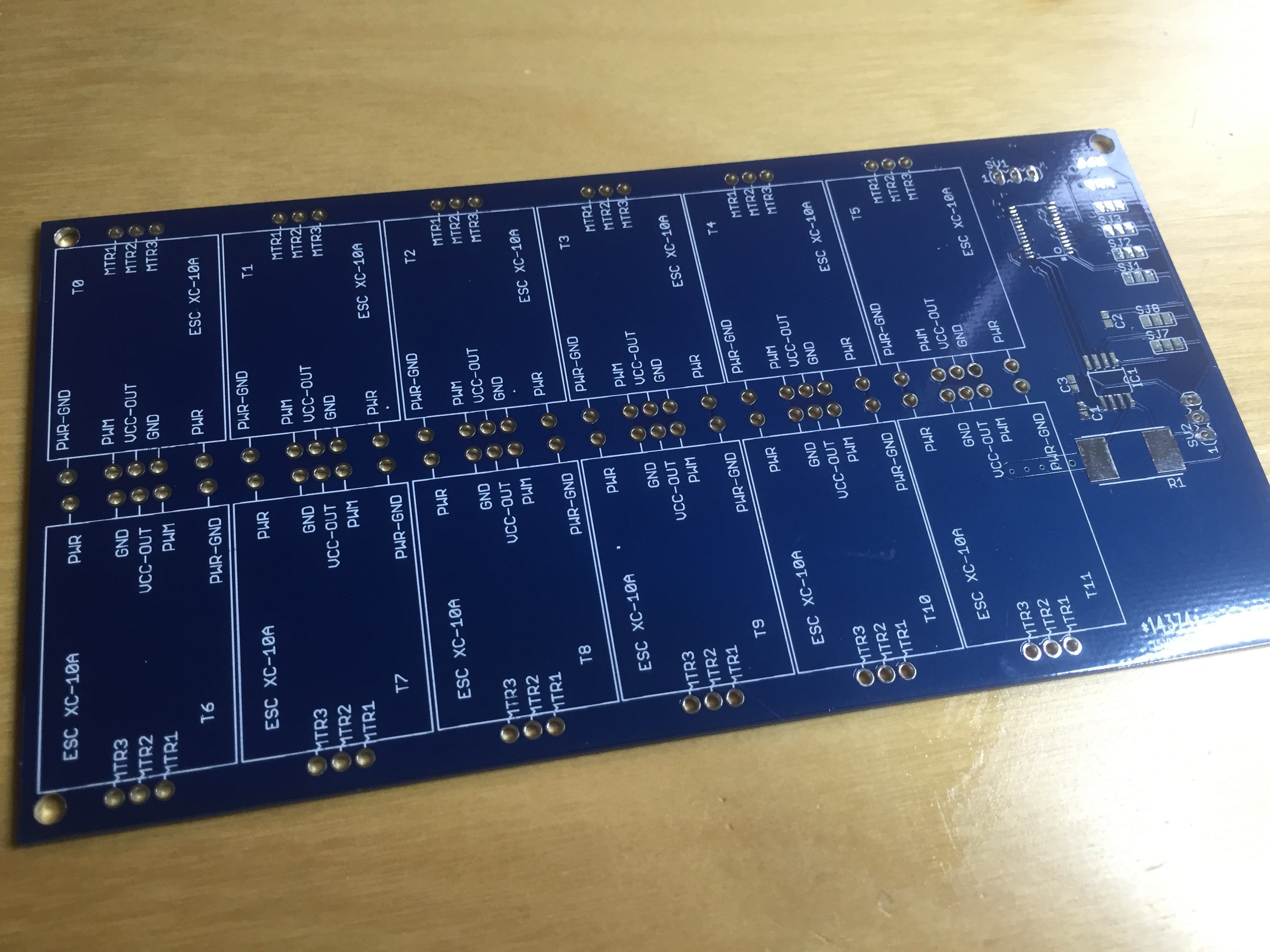
Because I need 12 of these, I decided to make a dedicated PCB; partly to organize everything, and partly to simplify the power and control signals. The board also contains a PCA9685 I2C PWM controller which allows a single I2C to set the speed and direction of each ESC.
The bare and populate PCB is shown below:
![]()
![]()
The missing chip on the middle-right was a current monitor, but I decided to move this functionality to the main board.
-
Water testing
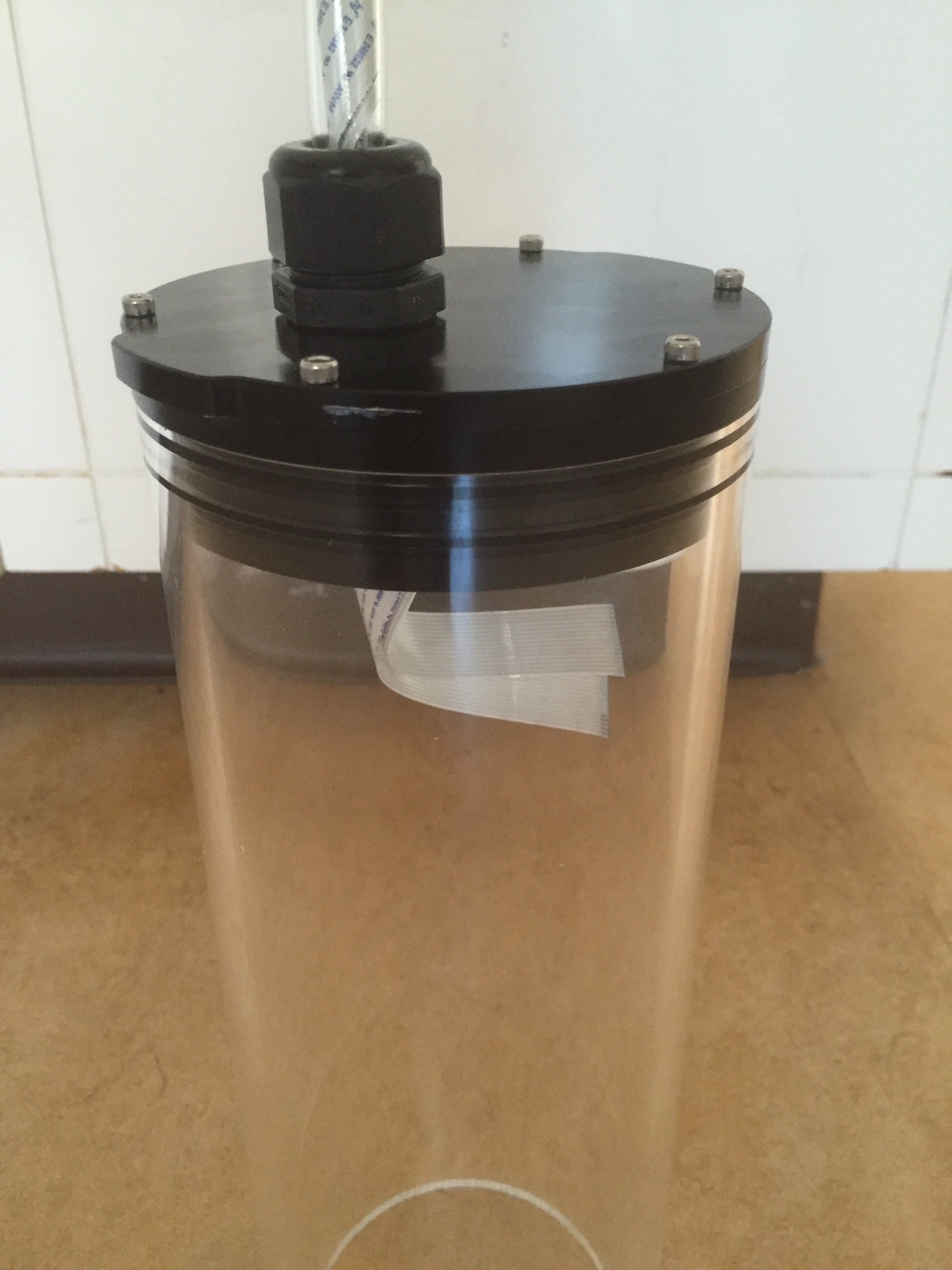
12/16/2015 at 22:19 • 2 comments24 hours later, and I'm ready to test the video penetrator. I've attached the endcap to the rest of the seal pieces, and inserted them into the 4" tube.
![]()
This is then upended and placed into an old gallons milk contains (with the top cut off) which has been filled with water, such that the penetrator is completely covered. No immediate leaks, so now I just have to waiting see. Ideally I'd later do a pressure test, but not sure how to do that yet.
![]()
-
Video Cable Penetrators
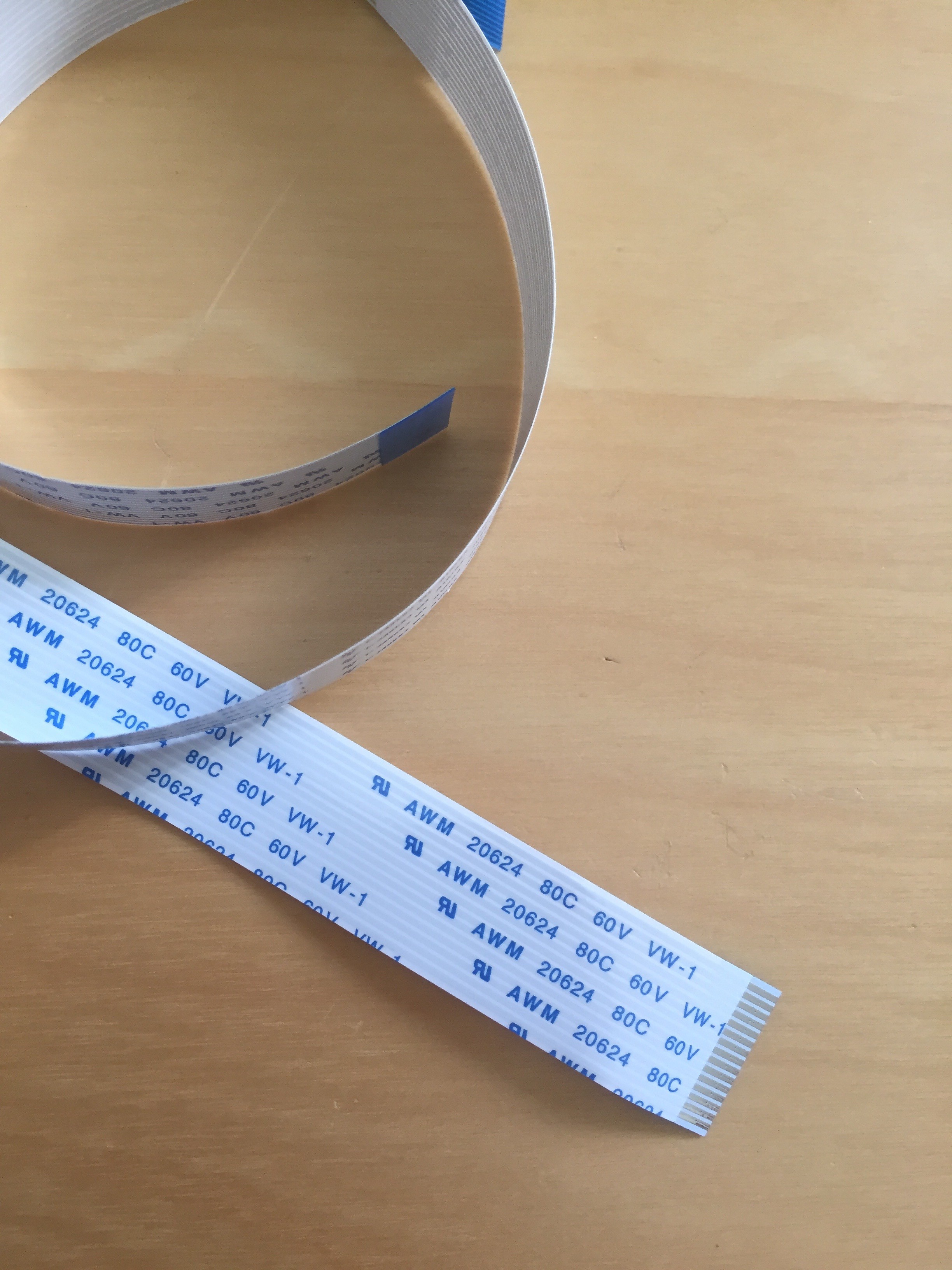
12/15/2015 at 20:43 • 0 commentsOne trickiness of using two Raspberry PI camera is the waterproofing of the cables connecting them to the Raspberry PI. The design of the ROV puts the pressure vessel contains the cameras at the front, and the containing the brains at the back. This means the video cables must somehow be waterproofed and fed between the two.
![]()
Above is the photo of the cables. While plastic coated, I don't feel comfortable just leaving them "as is" in the water. And, even if I did, there's no obvious way (to me) to penetrate the vessels with that long, flat, connector end.
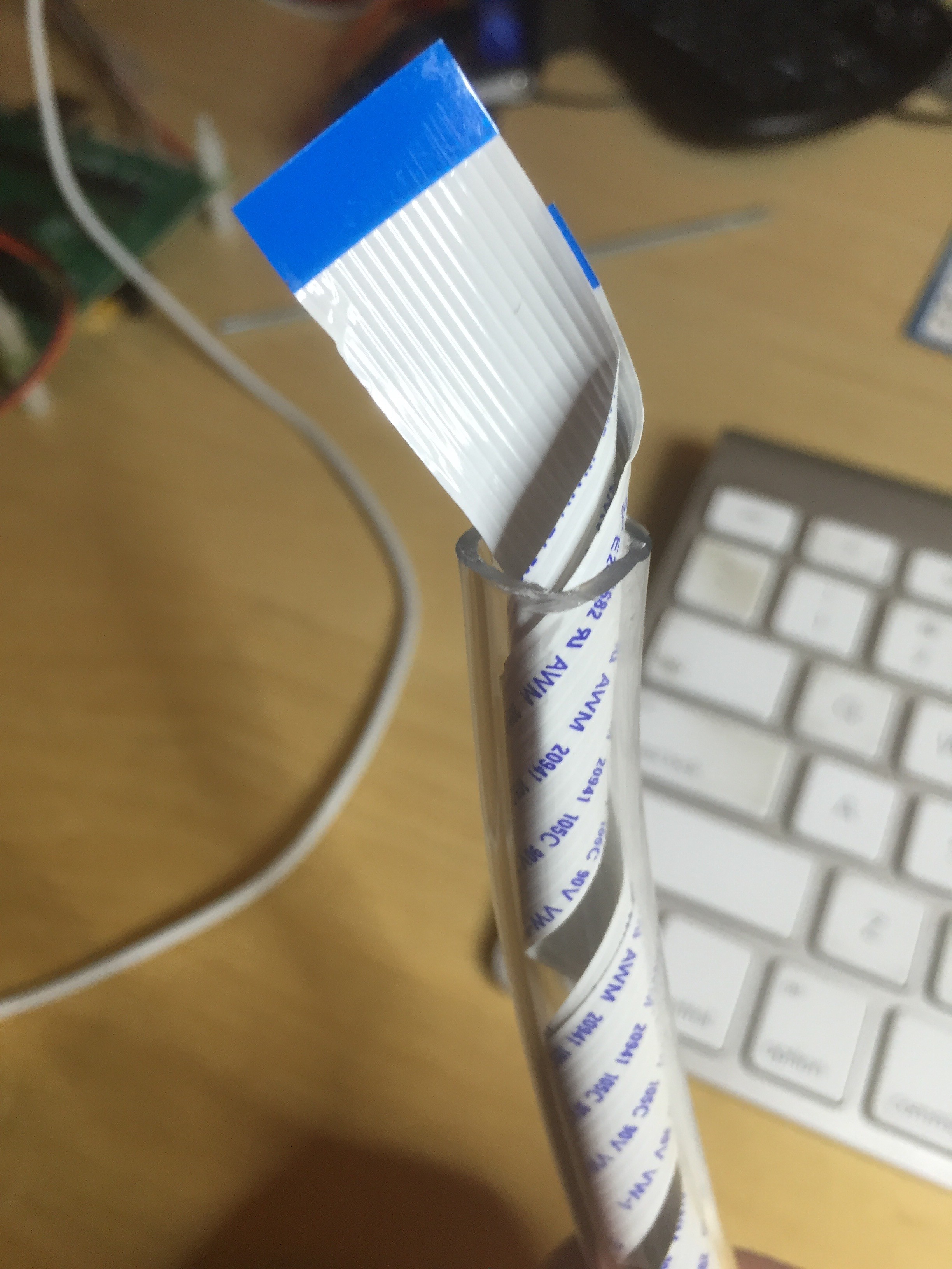
The solution was to "roll" the cables around the inside of some flexible pipe. To do this I first wrapped and secured the cables around a dowel (about 1/4" in diameter) and then fed the while things through some tubing. The result looks like this:
![]()
The other advantage to this method is that I can feed more normal cabling through the center of the tube (for power and servo control).
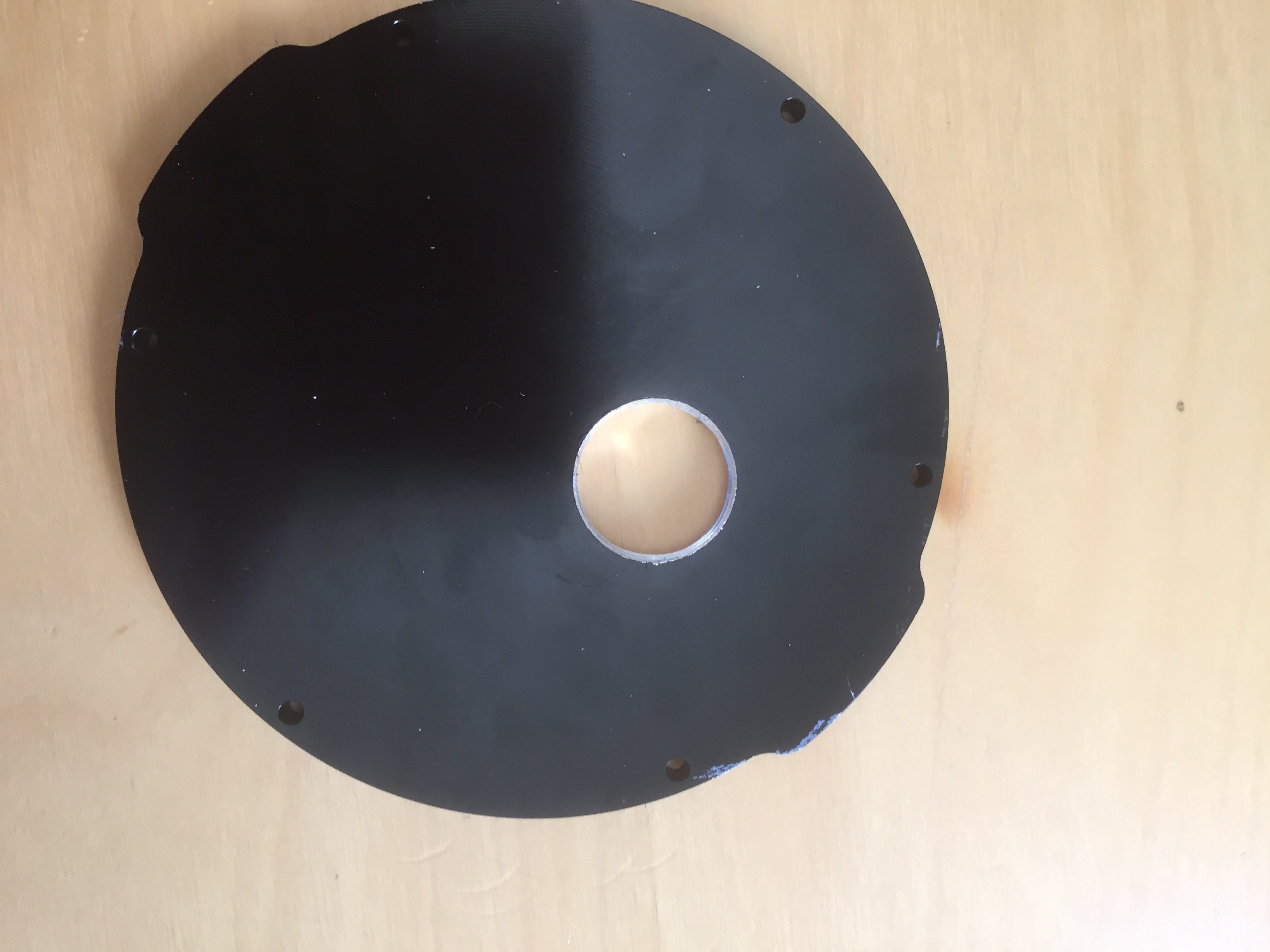
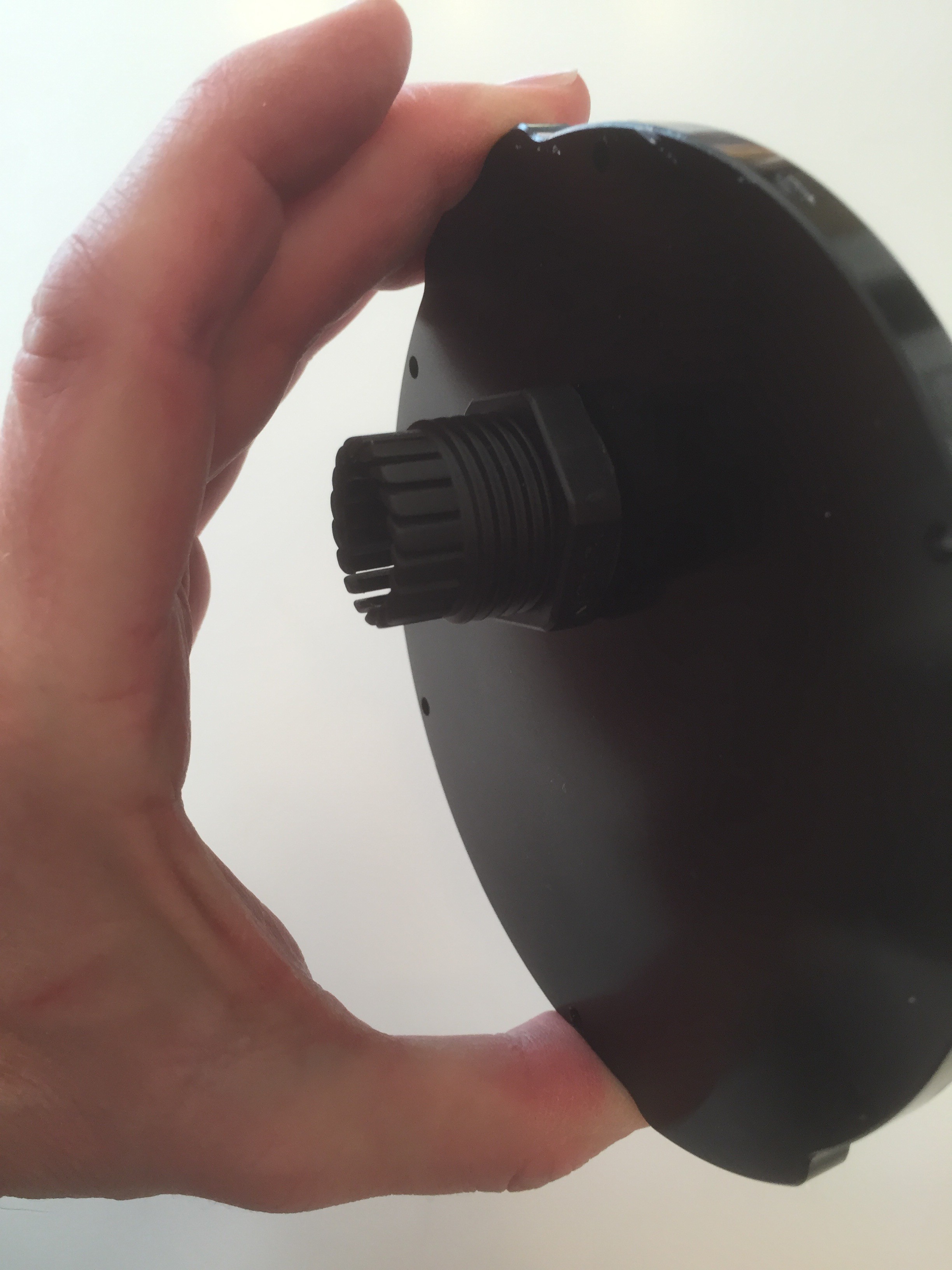
The next task was to feed this piping into vessel through the end cap. The end cap is from Blue Robotics and made of aluminum. Unsurprisingly there is no version for sale with a large enough hole in it for my piping, so I had to drill my own.
![]()
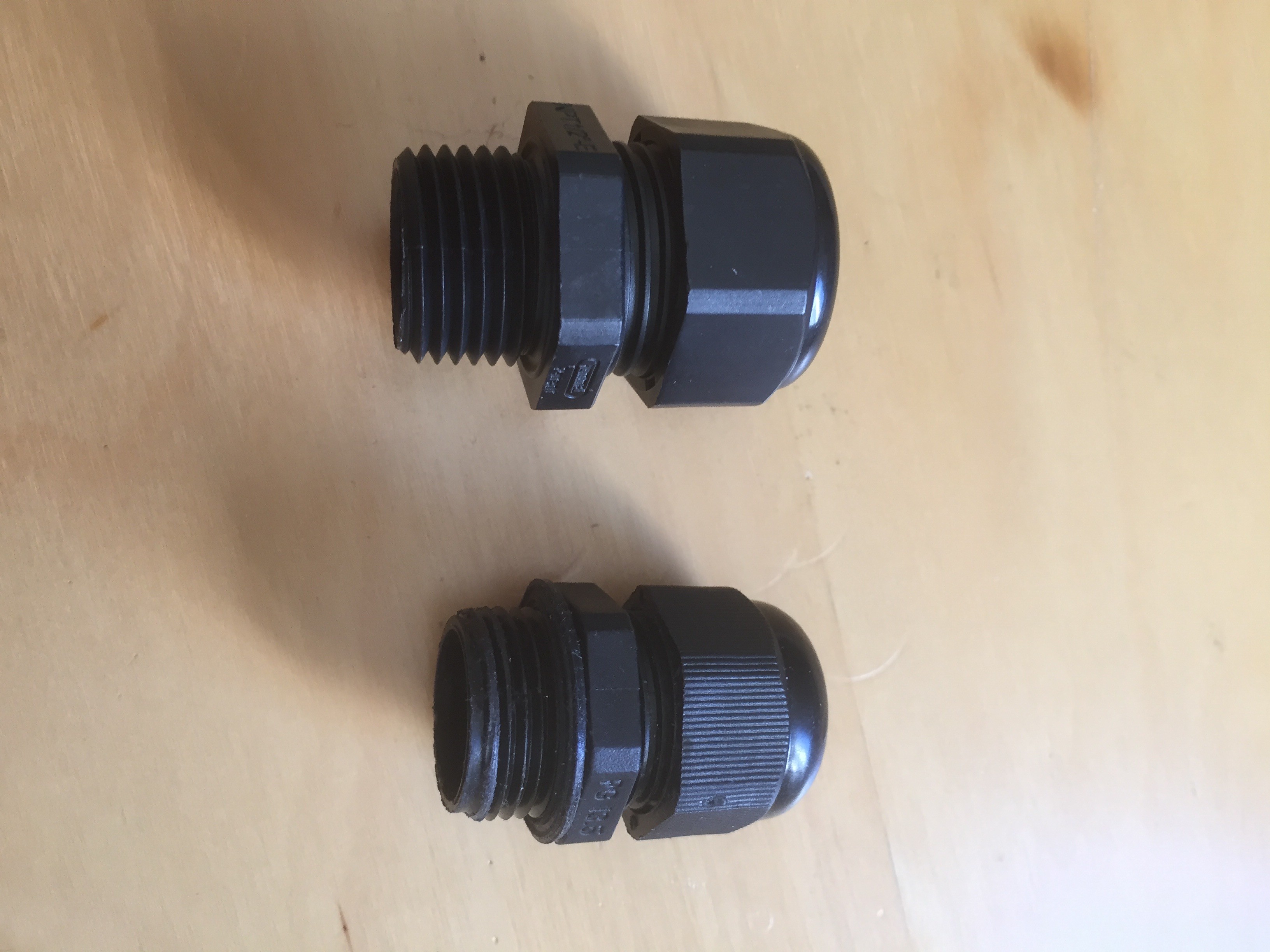
Of course, you can't just push a bit of piping though a hole and expect it to be water tight. So I needed to use a cable gland (also called a wire seal).
![]()
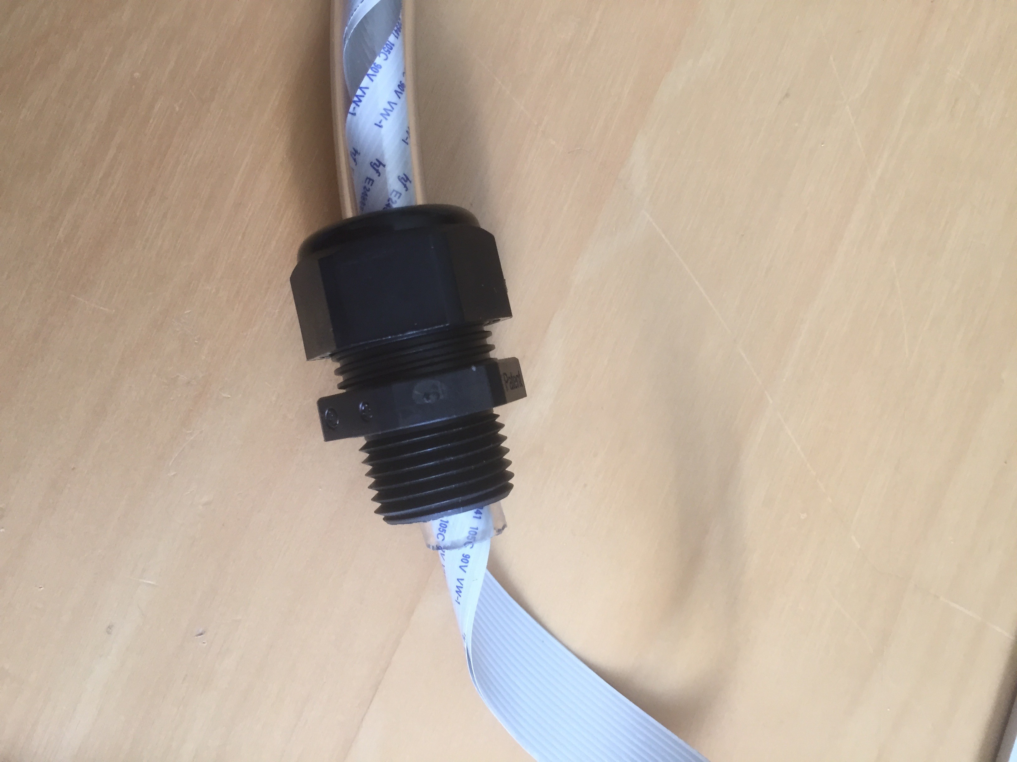
The above photo shows two cable glands, both with 3/4" screws to penetrate the end cap and both with 1/2" hole for the piping. The bottom one is a generic I bought from Amazon, the top one is from Ancor. Importantly, the Ancor version has a much longer thread for penetrating the end cap. The end cap is 1/4" thick, so the longer thread is essential. Here's the gland on the video pipe:
![]()
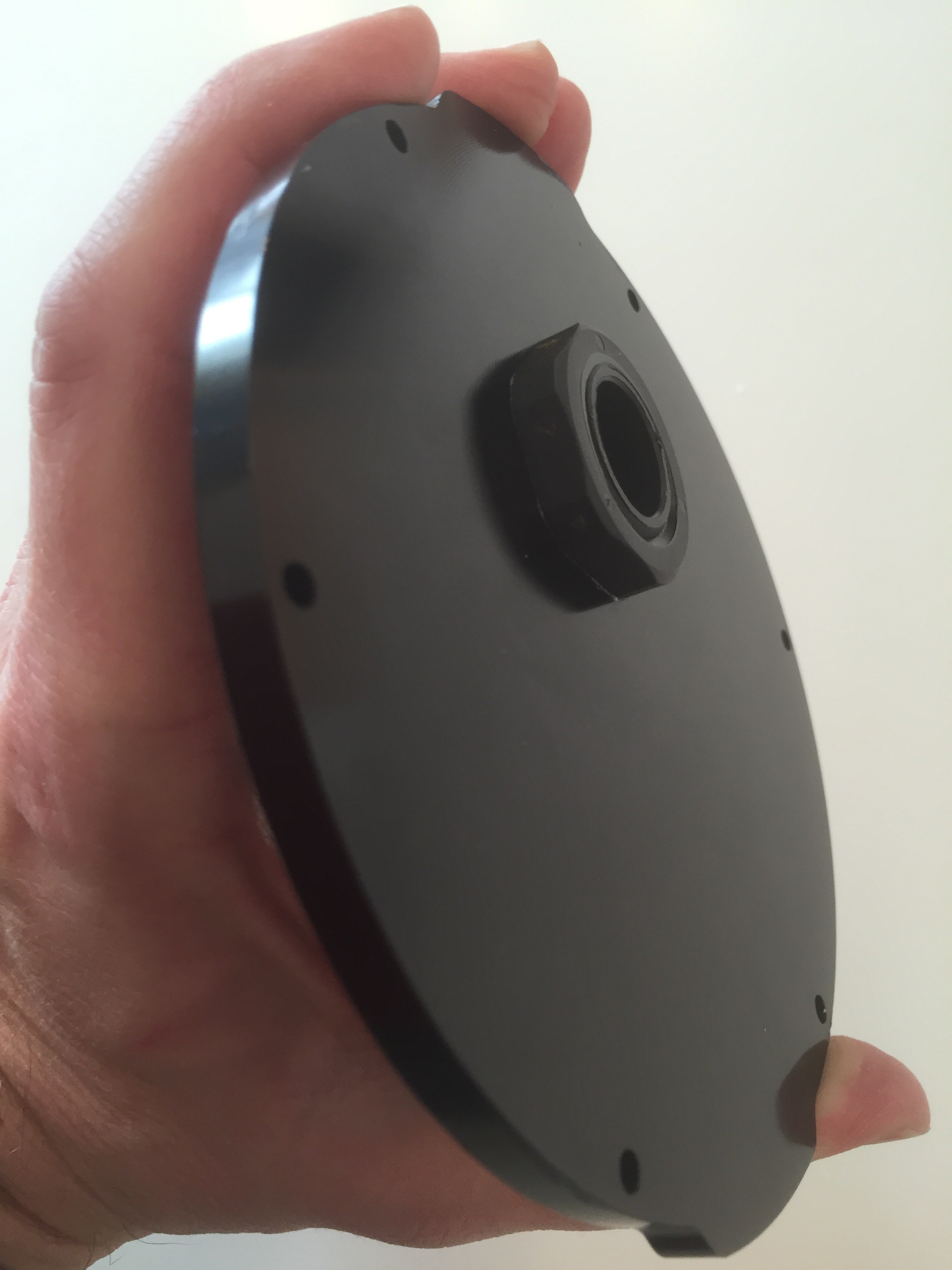
Finally, all the pieces were assembled. Although the gland was nicely snug against the aluminum hole, I added some JP Weld to bond the gland to the aluminum on the inside, and include an o-ring on the outside to prevent water leaking though any potential gaps. The result looks like this:
![]()
![]()
Now to give it 24 hours to cure, and then I can test to make sure it is waterproof. Fingers crossed.
-
Waterproofing
12/12/2015 at 00:13 • 0 commentsThere are a couple of general options to waterproofing electronics.
One is potting, the process of encasing your electronics in epoxy (or something similar) to keep them free from water. The big advantages with potting are that you can pot randomly sized or shaped devices and boards, and that there's no air-spaces left to be crushed at high pressure. The downside is that the electronics are permanently sealed away; so hope there's no failures.
The alternative options is to place the electronics in some sort of pressure vessel; the vessel keeps the water out, but allows access to the electronics when not in the water.
I expect to use both kinds of waterproofing in this project, but for the moment I'm thinking about a pressure vessel for the Raspberry Pi board.
I went through a few iteration on this. My original plan was to simply by an Otterbox (or equivalent). When their not making iPhone cases, they also make dry-boxes for divers. They seemed simple and ideal for keeping the electronics dry. However, I never could find a box that was the correct size for my craft and that was rated for sufficient depth.
So my second plan was to build some sort of sphere to contain the electronics. For this I'd use two polycarbonate hemispheres with flanges, and bolt them together. And while this is still a very appealing idea, it would require me to build a plate between the two spheres to contain the o-rings and grooves necessary to keep the contents water-free. I decided that was too difficult to do right now.
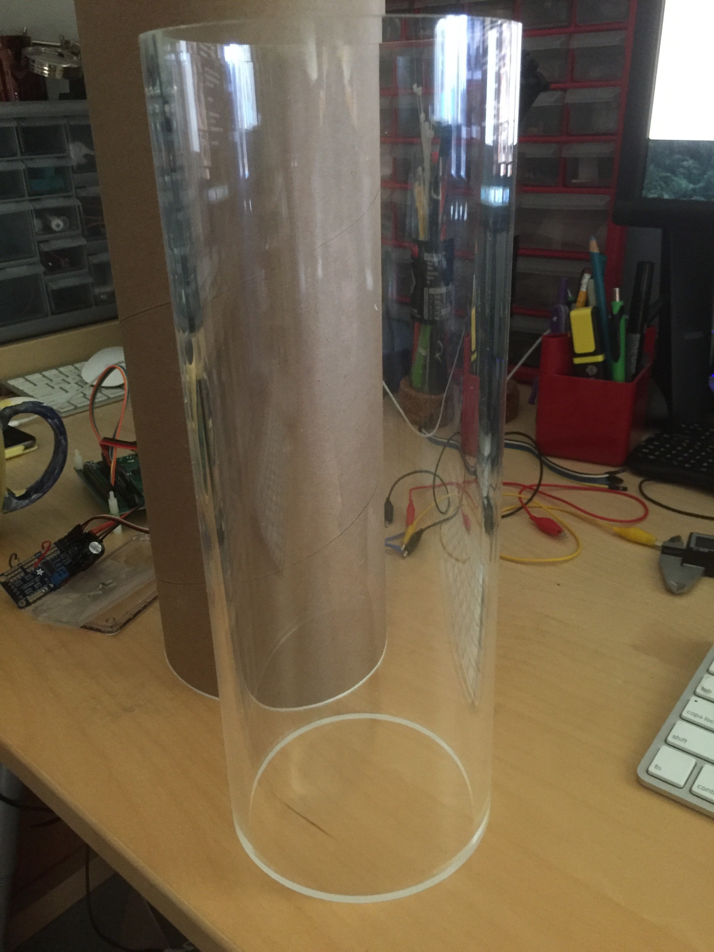
The third plan, and the one I'm using, utilizes acrylic tubes I bought from Blue Robotics. This has the advantage of being specifically design for underwater work, and comes with the necessary endcaps and o-rings to keep the inside water free.
![]()
-
Waterproof Servos
12/11/2015 at 21:24 • 0 commentsThe craft needs to have some kind of manipulator so it can interact with its underwater environment. That means I needed some kind of servo which will operate underwater. I chose to use the HiTec HS-5646WP and its analog sibling. There are a few waterproof servos available but I chose HiTec because it has a great reputation. The servos themselves are only IP67 rated so theoretically they're only good to about 1 meter, which isn't very much for an ROV. I hear chatter that they're good at much greater depths, so we'll see how they survive. I wouldn't be at all surprised if I end up rebuilding them (something like this by the Society of Robots perhaps).
![]()