-
Octomaps
07/20/2018 at 01:13 • 0 commentsThis post deals with the Octomaps library which deals with creation of an efficient way of storing, querying and include uncertainty in measurements. Octomaps are data structures t represent 3d space. There are many approaches for modelling 3D space in the robotics domain by creating voxels.
Octomaps differ from them as it does not suffer from space constraints and the problems such as inability to model unknown and free space. Octomaps can model uncertainty in obstacles in the occupancy grid by incorporating probabilistic updates of the occupancy maps. Octomaps can be used to represent voxels at different resolutions. The datastructure used for their implementation are octrees.
Every Octree has eight children. Basically the root of the tree is the area that you are modelling. This region can be unknown initially as the restriction here is the size that you want your octree to be. If the size of the Octree should be small then a dynamically exploring a bigger area would yield leaves with coarser resolutions and vice versa. To include free space in the modelling Octrees explicitly include two types of node: Occupied and Free. Unknown nodes are not generated. Each root is a volume in real world. The children are obtained by dividing the root volume into eight equal parts (voxels) something similar to the four quadrants that we normally use in 2 dimensions. The occupancy values are updated using some distance measurement sensor. The voxels containing the endpoints of the sensor readings are marked as occupied in a discrete map and updated according to some predefined formula in a probabilistic occupancy grid. The region on the ray between the sensor and the endpoint is marked as free and the octree is updated accordingly.
Currently I am looking at ways to represent the Lidar scans that would be acquired using Octomaps and get a 3D map for the environment. Octomaps are purely for generation of maps. Octomaps are however flexible as they are available as a opensource C++ library which can be included in any C++ project. I am also looking to study the Hector-SLAM package for ROS which is restricted to ROS from what I know. Hector-SLAM though includes mapping, localization which is highly desirable if you want to get started with your planning projects. Currently I am looking to study both of them and try to implement some examples -
SITL
07/11/2018 at 12:29 • 0 commentsCurrently I am working with simulating the project in ArduPilot and then taking it to hardware. ArduPilot SITL is one way to simulate the flight and the sensors. I am pretty sure that the SITL does have a Laser scanner simulator but am not sure what is its field of view. The process to download and run SITL on a Ubuntu 16.04 is as follows:
- Open Terminal and clone the git repository.
git clone git://github.com/ArduPilot/ardupilot.git cd ardupilot git submodule update --init --recursive- The next step depends on the operating system that you are using. Go to the installation instructions for your OS on Ardupilot website for more details. For Ubuntu 16.04 you just need to run a script:
cd ardupilotcd Tools/scripts
./install-prereqs-ubuntu.sh- Add the following to the end of your bashrc file and source it.
export PATH=$PATH:$HOME/ardupilot/Tools/autotest export PATH=/usr/lib/ccache:$PATH. ~/.bashrc
- Start the simulator.
cd ardupilot/ArduCopter sim_vehicle.py -w #to load the default parameterssim_vehicle.py --console --map
The copter can be run in several modes:
1. Guided: To run in Guided mode do the following.
mode guided
arm throttle
takeoff 40
For more detailed commands and information goto:
http://ardupilot.org/dev/docs/copter-sitl-mavproxy-tutorial.html
2. Auto: For navigating the copter in Auto mode do the following:
wp load ..\Tools\autotest\copter_mission.txt arm throttle mode auto rc 3 1500 -
LIDAR message
07/11/2018 at 12:14 • 0 commentsI am planning to use ROS to interface the Lidar with the copter. The LIDAR messages are published using the message format defined in the sensor_msgs/laserscan message type in ROS. The message consists of :
std_msgs/Header header
float32 angle_min
float32 angle_max
float32 angle_increment
float32 time_increment
float32 scan_time
float32 range_min
float32 range_max
float32[] ranges
float32[] intensitiesThe angles are in radians. angle_min is the start angle from which the LIDAR starts taking observations in one scan. It then takes observations by incrementing the angle with steps equal to angle_increment until it reaches the angle_max when the scan completes. The time between two scan is equal to time_increment. Scan_time is the time to complete one scan in the FOV defined for the LIDAR. Range_min and range_max are the minimum and maximum values that the LIDAR can detect. Ranges give you the distance observation that has been calculated by the LIDAR.
-
Extended Kalman Filter
03/24/2018 at 03:39 • 0 commentsI had explained Kalman filter in the last post. What happens when the motion model and observation model is not linear. In robotics, the linear case occurs rarely. So algorithms that can handle non-linear models can be used to localize. The Extended Kalman filter is one such algorithm.
The observation and motion model for non-linear case can be represented by:
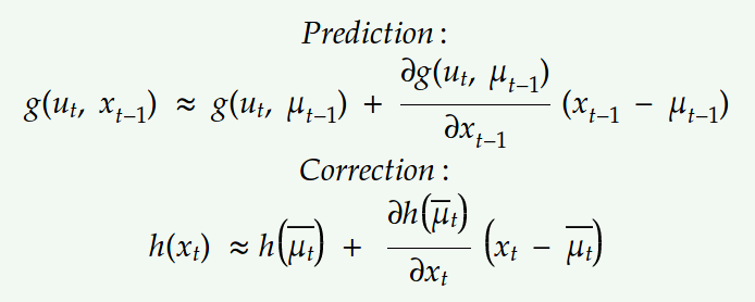
Here g and h represent the non-linear model. The other notations are the same as those in Kalman filter equations. After applying the non-linear models to the state x which in our case is a gaussian, we get a distribution that is not a gaussian. We try to approximate this distribution with a gaussian to get the final state. This is done by using Taylor expansion which linearizes the function at the mean.
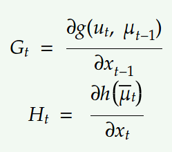
Using first-order Taylor expansion at the mean we can approximate the motion and observation model with the following linear model:Let the jacobians for motion and observation model be,
Substituting the above linear model into the Bayes filter equations we get,
Replacing the Kalman filter equations with the new linear model we get:
The above equations show the Extended Kalman filter where we just linearized the non-linear modelwith Taylor expansion. This method however performs linearization just at the mean due to which it is not representative of the actual non-linear model. It works well in cases where the non-linearities are moderate.
-
Kalman Filter
03/23/2018 at 23:25 • 0 commentsIntoduction:
Kalman filters can be intrepreted as Bayes filter with the gaussian linear case. There application range from economics to weather forecasting to satellite navigation. If models are not linear the beliefs do not remain gaussian and we can not work with a simple kalman filter.
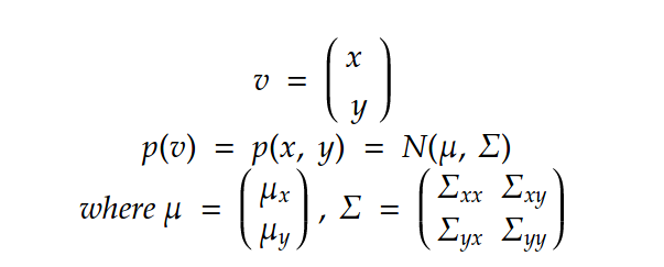
A multivariate Gaussians can be described:
Let v be a multivariate gaussian distribution:
The marginal of x can be defined as:The conditional of x with respect to y is:
The kalman filter linear and observation models can be thus represented by:
where x represent the motion model and z represent the observation model. Here the motion noise epsilon is zero mean gaussian with covariance R and the observation noise is zero mean with Q covariance.
Substituting these values in the Bayes filter motion and observation models we get,The above values can be substituted in the prediction and correction step below:
to get the final Kalman filter equations described in the algorithm below:
The first two equations show the predictions for the mean and covariance of the state and the last two equations give us the final belief of the state considering the observations. Once again, all of this is just applicable when we have linear motion and observation model. For non-linear models we consider the Extended Kalman filter that I would be explaining in my next post.
-
SLAM
03/16/2018 at 03:14 • 0 commentsSimultaneous Localization and Mapping (SLAM):SLAM is a probabilistic technique to construct and update maps for navigation while localizing the object pose in the map. The problem appears to be a chicken and egg problem as to localize the vehicle we need a map and to update the map we need to know the pose of the vehicle. This problem can be solved through multiple approximate techniques such as Extended kalman filters and Particle filters.
The problem can be formulated mathematically as finding:
Input: robot's controls inputs u and observations z.
Output: Map of the environment m and the pose of the robot x
This can be done using bayes filter. Bayes filter is a two step process: Prediction and Correction.
Predicton step predicts the state of the vehicle using the motion model, control inputs and previous belief while the correction step reduces the uncertainty using the observation model. The motion model describes the distribution of the current state of the system given the control inputs for this time step and the previous belief of the pose of the vehicle. This can be represented mathematically as:
The predicted state of the system is :
The Sensor model or the Observation model is responsible for reducing the uncertainty that is introduced by the random nature of the problem. The predicted state is:
This belief value is the current pose of the system.
There are multiple ways to implement the Bayes filter:
- Kalman Filters which deals with gaussian distributions and linear models
- Particle Filters which deal with non-parametric arbitrary models
Kalman filters deal with the linear gaussian case. By linear we mean a linear model and by gaussian we mean gaussian noise is associated with the pose and observations.
QuadRotor testBed for localization and mapping
I am trying to build a test bed for trying out localization and mapping algorithms.
 int-smart
 Here g and h represent the non-linear model. The other notations are the same as those in Kalman filter equations. After applying the non-linear models to the state x which in our case is a gaussian, we get a distribution that is not a gaussian. We try to approximate this distribution with a gaussian to get the final state. This is done by using Taylor expansion which linearizes the function at the mean.
  Let the jacobians for motion and observation model be,
 Substituting the above linear model into the Bayes filter equations we get,
 Replacing the Kalman filter equations with the new linear model we get:
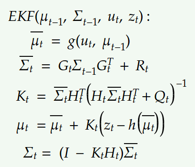 The above equations show the Extended Kalman filter where we just linearized the non-linear modelwith Taylor expansion. This method however performs linearization just at the mean due to which it is not representative of the actual non-linear model. It works well in cases where the non-linearities are moderate.
 The conditional of x with respect to y is:
 The kalman filter linear and observation models can be thus represented by:
 where x represent the motion model and z represent the observation model. Here the motion noise epsilon is zero mean gaussian with covariance R and the observation noise is zero mean with Q covariance.
 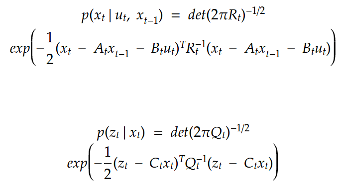 The above values can be substituted in the prediction and correction step below:
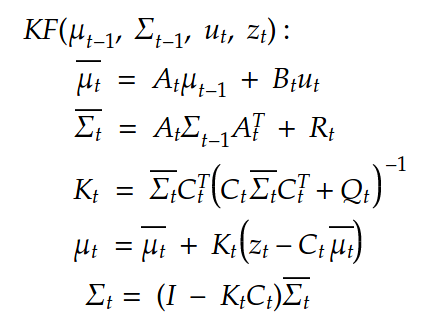 The first two equations show the predictions for the mean and covariance of the state and the last two equations give us the final belief of the state considering the observations. Once again, all of this is just applicable when we have linear motion and observation model. For non-linear models we consider the Extended Kalman filter that I would be explaining in my next post.