 Moritz Walter
-
1Step 1
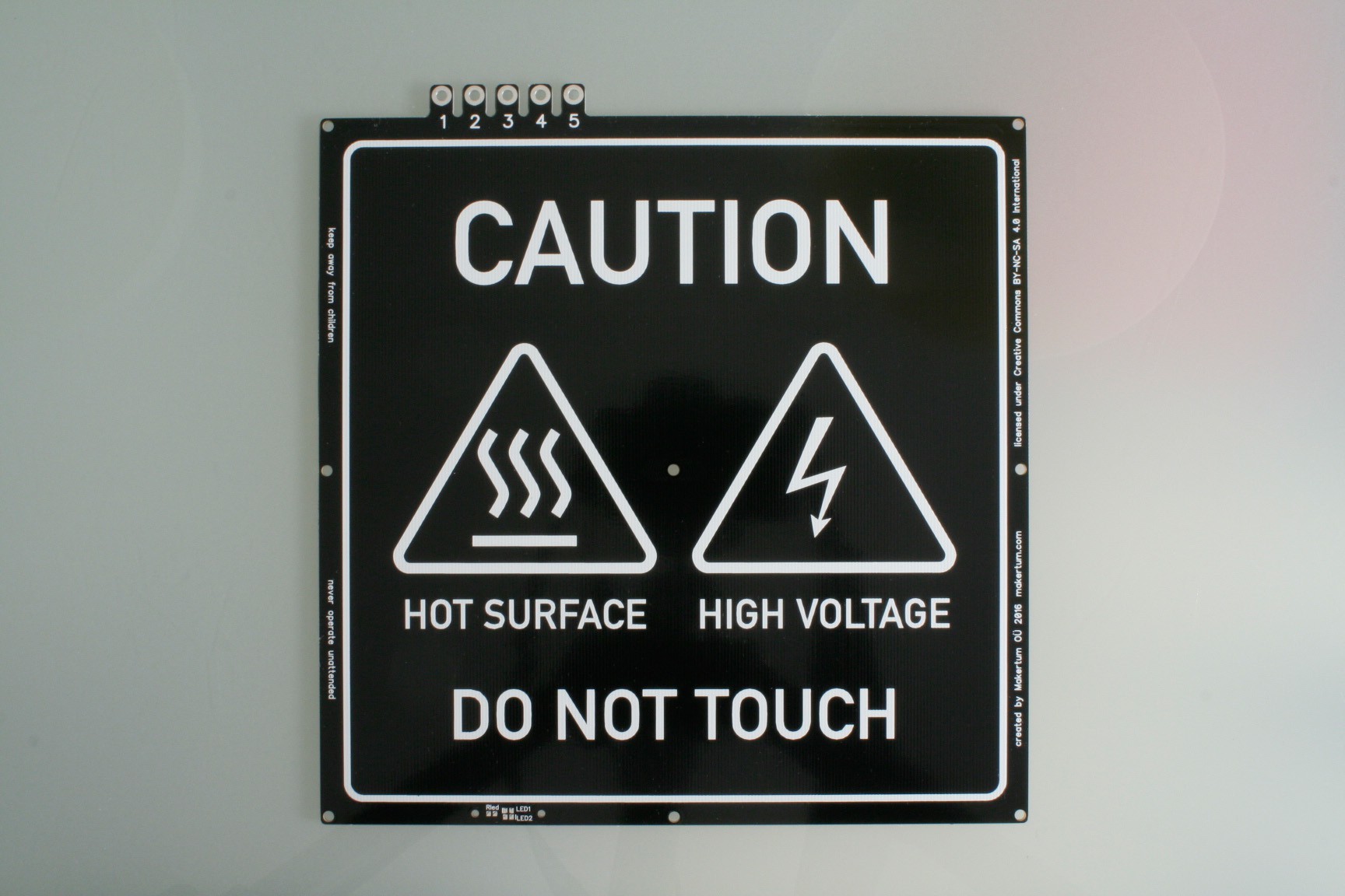
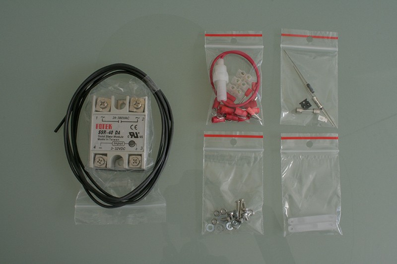
Check received parts
You should have received:
- 1 pcs PCB
- 1 bag with screws
- 1 bag with electronics
- 1 bag with cable lugs, screw joint and cable fuse holder
- 1 bag with polycarbonate LED cover
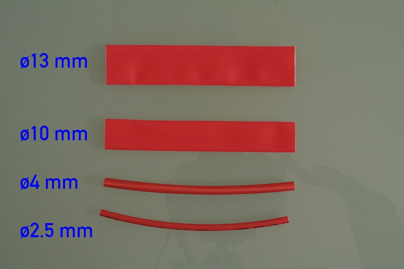
- 4 pcs shrink tubes (+ 4 spare)
- 2 meters of heat resistant supply cable
- 1 SSR (if you chose the SSR option)
As shown below:
![]()
![]()
![]()
-
2Step 2
SMD soldering
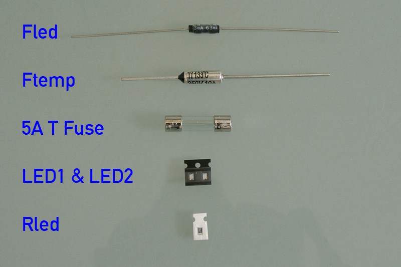
Take the bag with the electronic parts, some of them are very tiny, so don't lose them. We dropped the Fled from the design, so don't worry if it's not there:
![]()
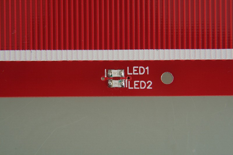
Top side
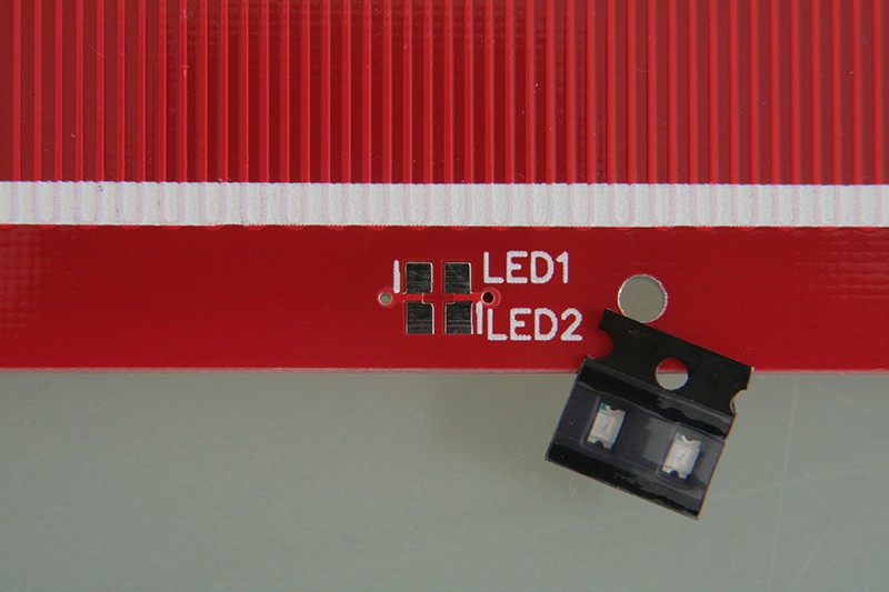
As long as the bottom side is still unpopulated, lets solder the 0805 SMD LEDs to the top side:
![]()
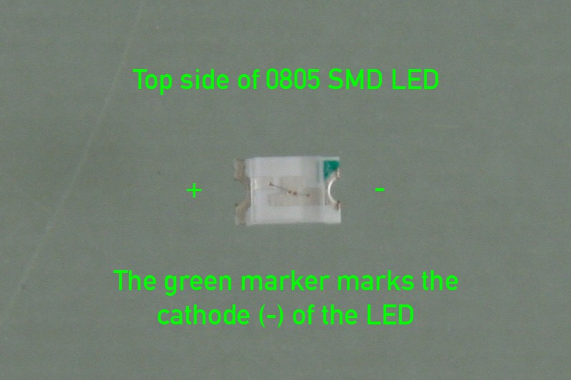
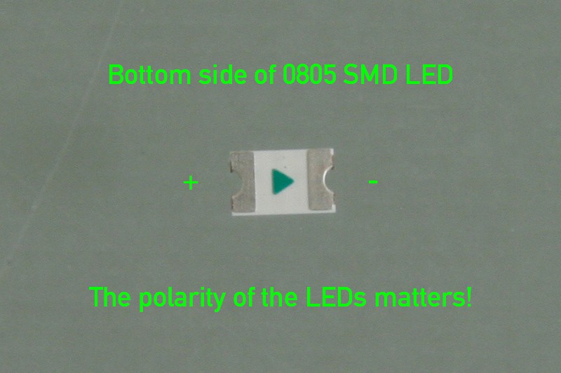
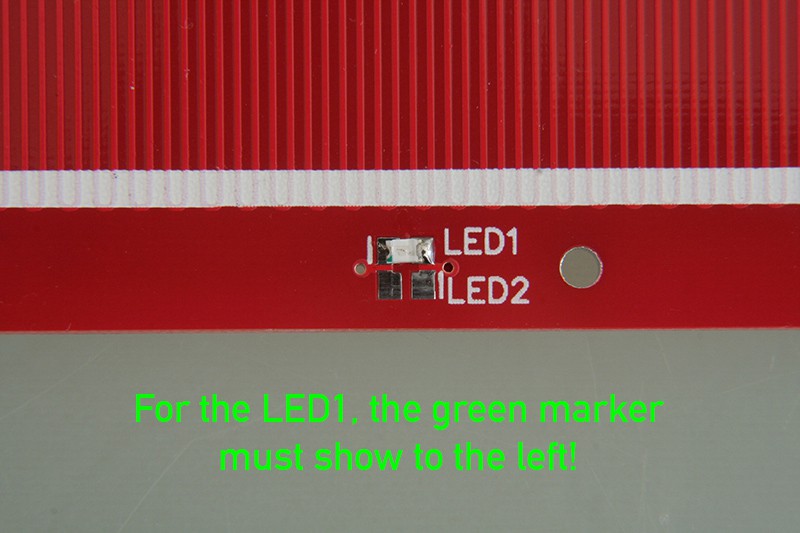
Unpack them carefully and mind the polarity of the LEDs:
![]()
![]()
If you do not own reflow equipment, and must hand solder the parts, it's recommended to first add a little solder and flux to the right pad (if you're left-handed: left pad) of LED1 with your soldering iron:
![]()
Then, hold LED1 in place with tweezers, mind the correct polarity (see below) of the LED. Melt the pre-applied solder with your soldering iron until the LED has good solder contact with the pad. Be careful not to overheat the LED.
![]()
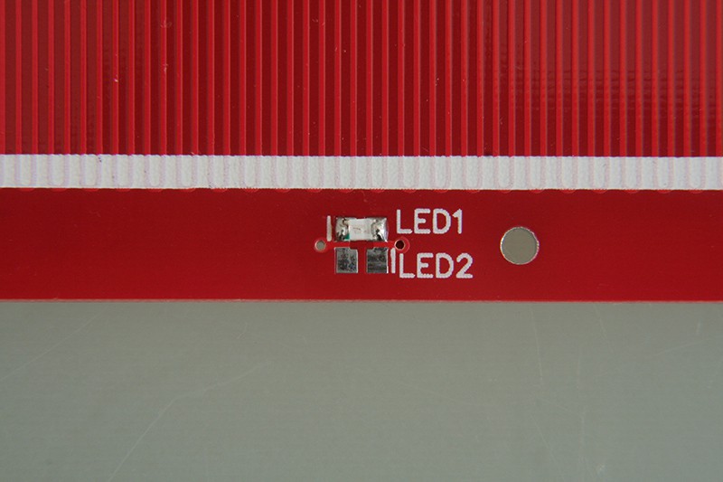
Now, that the LED is held in place, you can easily solder the other pad. A little flux helps spreading the solder. Careful with the heat!
![]()
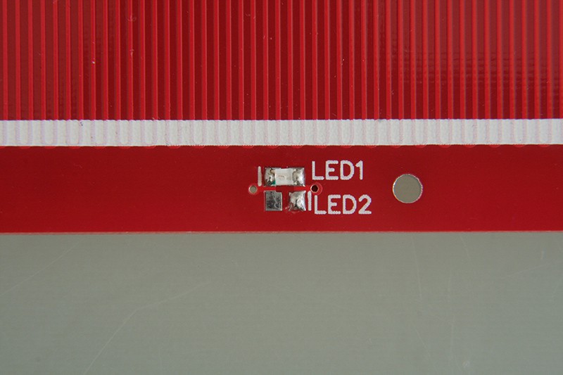
The LED2 just goes like the first, add a little solder and flux to the right (left-handed: left) pad..
![]()
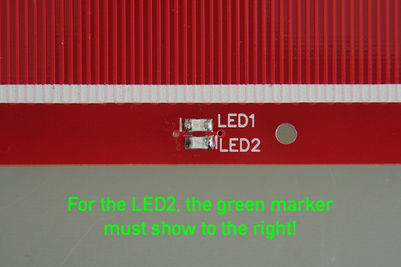
Then place the LED with tweezers. Again, mind the polarity (see below), since LED2's polarity is inverted to the polarity of LED1. Melt the pre-applied solder again until the LED has good contact with the pad. Careful with the heat!
![]()
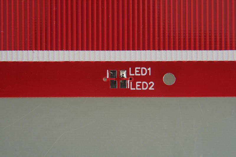
To complete the top side, solder the second pad of LED2:
![]()
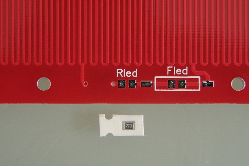
Bottom side
I recommend to start with the 0805 SMD resistor:
![]()
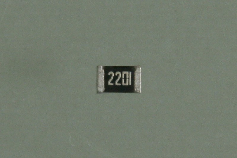
Unpack the resistor carefully:
![]()
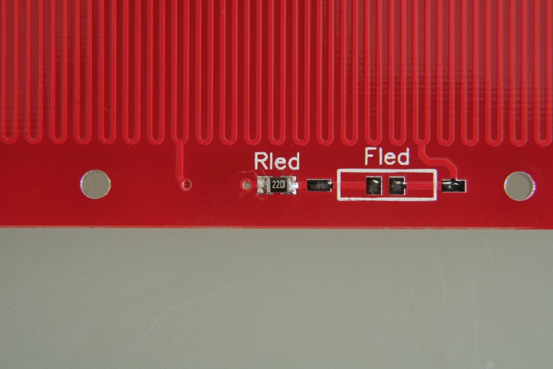
Then solder it using the same technique as with the LEDs. Be careful not to overheat the resistor.
![]()
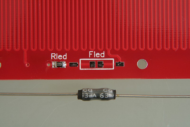
The next thing to solder is the 63 mA pico fuse "Fled". If you ordered a pre-production board, you can skip this part, since the Fled was dropped from the design:
![]()
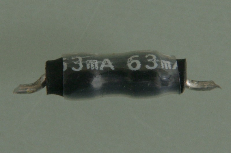
The fuse "Fled" needs a bit of preparation, use pliers to bend and cut the wires as shown below to make it surface-mountable:
![]()
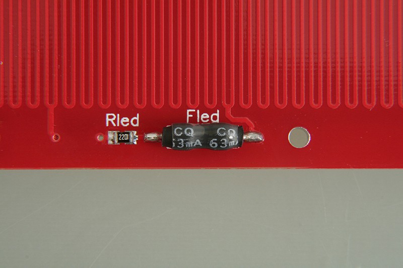
Then solder it to the PCB using the same technique as with the other components. Be careful not to overheat the tiny fuse.
![]()
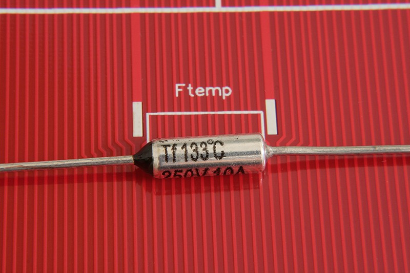
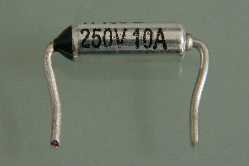
The last component on the bottom side is the thermal fuse:
![]()
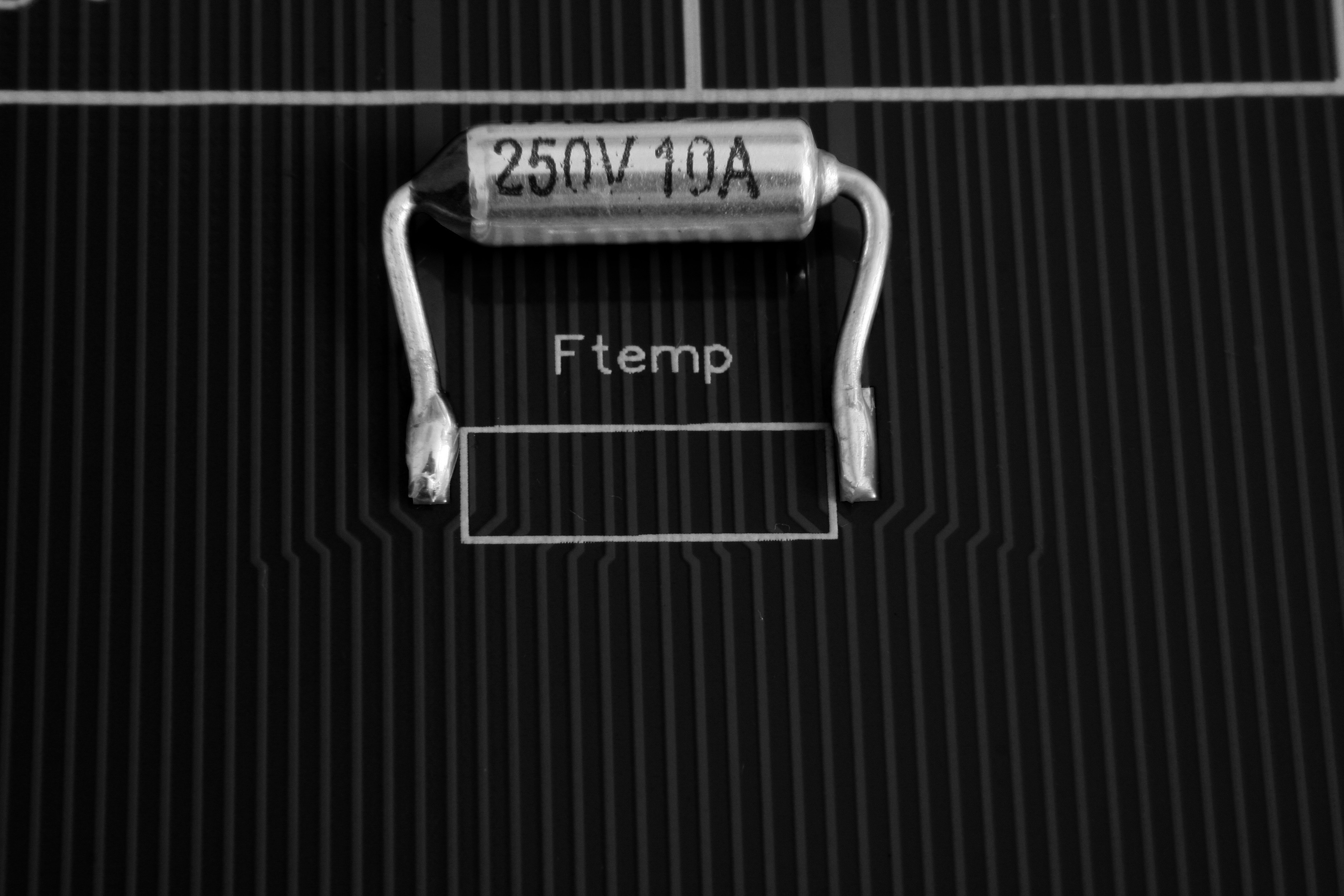
This fuse also needs a bit of preparation. Use your pliers to bend and cut the wires to make the fuse surface mountable. Make sure the fuse's body can have good contact with the PCB when mounted.
![]()
Start by applying solder and flux to the right pad. Then hold the fuse in place and melt the pre-applied solder. Make sure you don't overheat the temperature sensitive component. Check if the fuse's body touches has good contact with the PCB before you solder the second pad. If you can't align it just right, you can use thermal compound between the fuse and the PCB. The solder connections on both pads must be excellent, since they will have to carry the operating current.
![]()
-
3Step 3
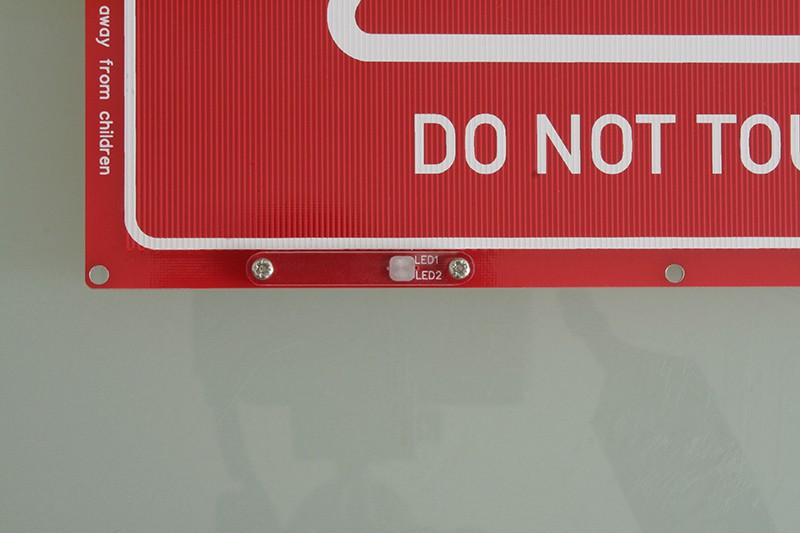
Install polycarbonate LED cover
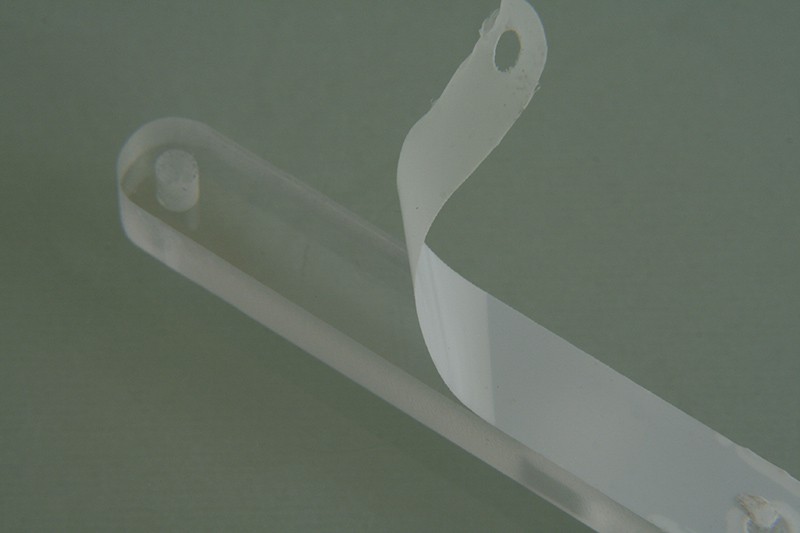
The polycarbonate cover protects the user from touching the LED pads, which conduct mains potential. Make sure it's installed properly at any time. Pre-production boards come with only a single-sided cover.
Start by peeling of the protective film from both halves of the cover:
![]()
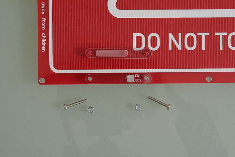
Take the two M2 screws and nuts from the bag with the screws and start assembling the cover as shown below:
![]()
Put the M2 screws through the top half of the cover and through the PCB.
![]()
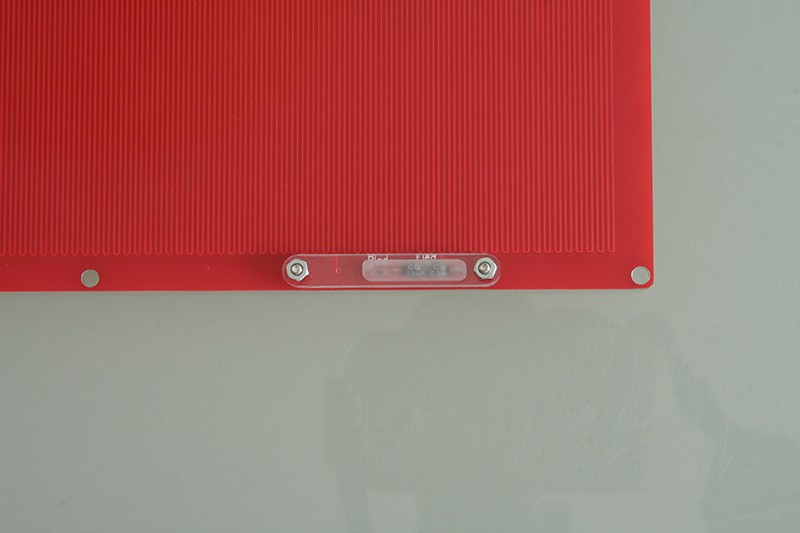
Turn the PCB arround and install the bottom half of the led cover. Counter the screws with the M2 nuts.
![]()
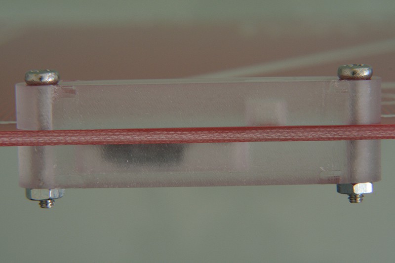
Make sure both screws are tight, use Loctite if necessary.
![]()
-
4Step 4
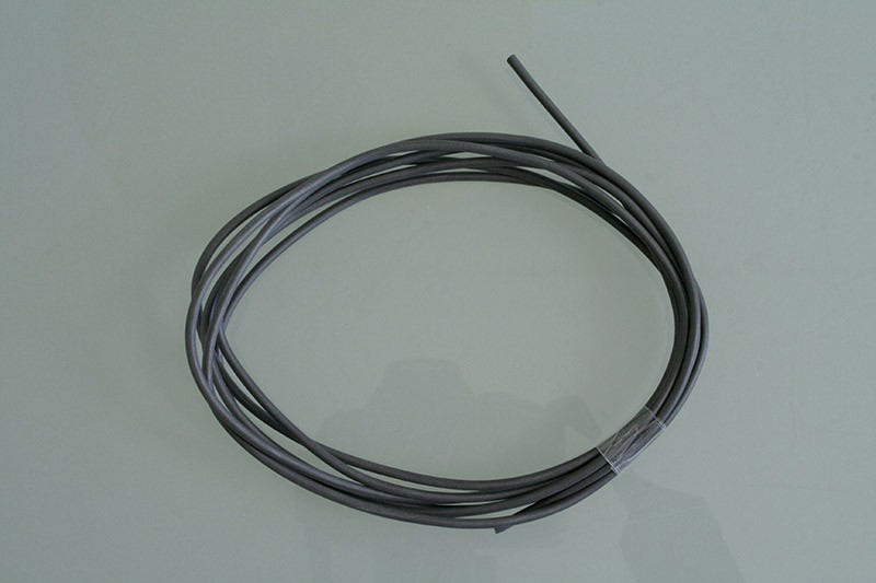
Wire prepping
The package contains two meters of flexible heat resistant silicone wire that will supply your heated bed with power. In this step, we will cut that to length and add a few crimp connectors here and there to get all the cable pieces we need.
![]()
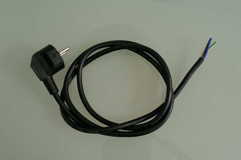
Power cable
You will need a power cable that works in your country, since the power cable is not part of the kit.
![]()
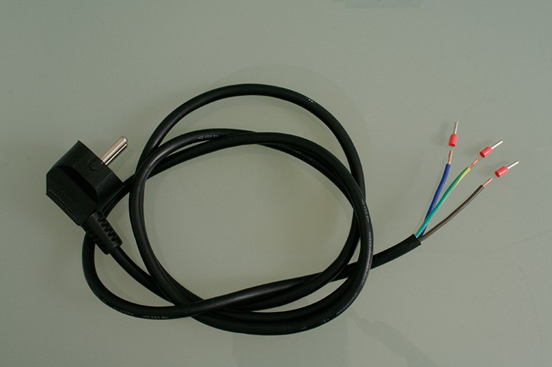
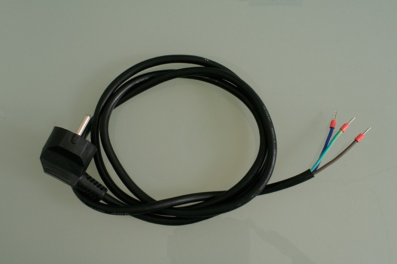
Strip the ends carefully, make sure you don't harm the inner wires when stripping the outer insulation. Grab three wire end ferrules from the cable lug bag.
![]()
Then, crimp all three ferrules to the wire ends. This is how your finished power cable should look like:
![]()
Jumpers
We need two jumper wires, one for configuring the heated bed to your mains voltage (110 V~ vs 230 V~) and one to bridge over from the power cable to the SSR.
First, cut TWO pieces of 8 cm from the provided cable.
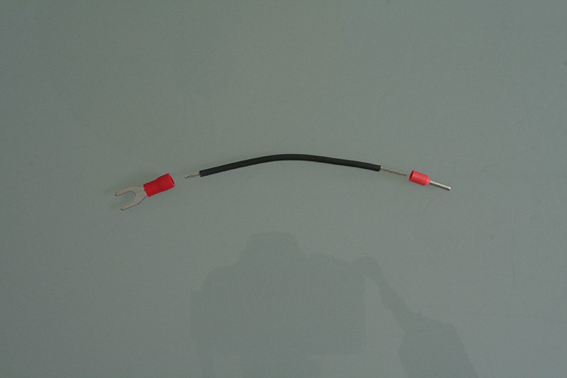
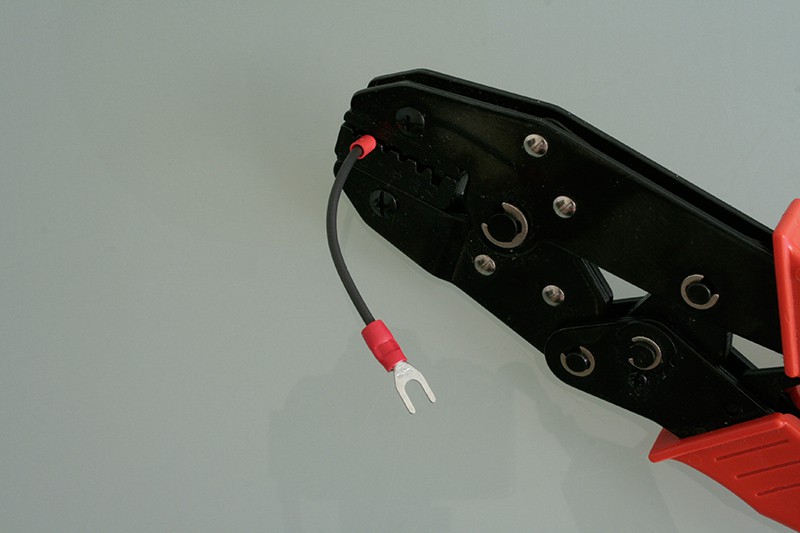
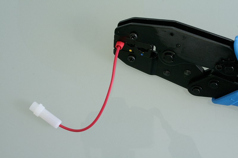
Then, for the SSR jumper, grab one fork cabe lug and one wire end ferrule and strip the ends of the wire to fit the lugs:
![]()
Crimp the cable lugs in place using a crimping tool. Mind that you'll need two different crimping tools for the ferrules and for the cable lugs. If you don't have the right crimping tool at hand, you can solder also the cable lugs after removing the red plastic skirt. Soldering the ferrules is not recommended, but they can usually be crimped with regular pliers.
![]()
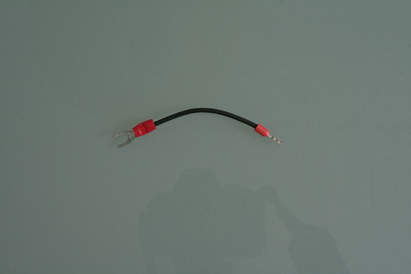
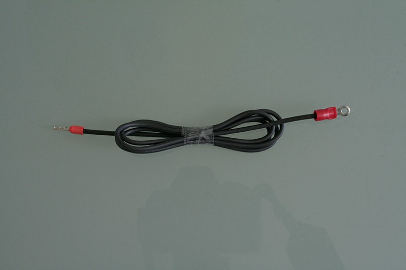
This is how the finished SSR jumper should look like:
![]()
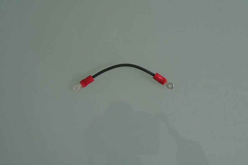
Next comes the configuration jumper, grab the second 8 cm wire pice and two ring cabe lugs from the cable lug bag. Strip the ends of the wire to fit the lugs to fit the lugs.
![]()
Crimp the cable lugs in place using a cable lug crimping tool. This is how the finished configuration jumper should look like:
![]()
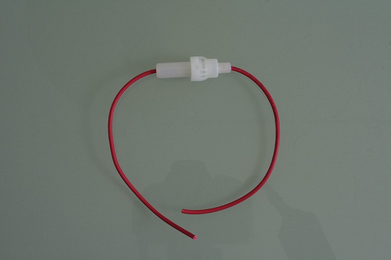
Phase cable
For beeing able to guide you through this, I'll call one of the supply wires the "phase cable" and the other the "neutral cable". This is pure notion, it could also be called Mr. Fizz or Max Power.
The "phase cable" is the same for both 110 V~ and 230 V~ configurations.
First, grab the cable fuse holder from the cable lug bag and cut it open in the middle:
![]()
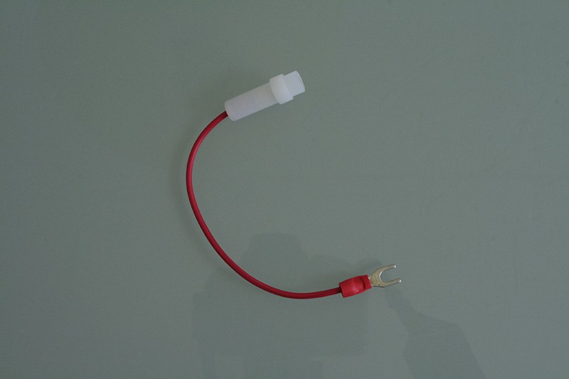
Then, open the fuse holder, take the left half (see below), grab a fork cable lug from the cable lug bag and strip the wire to fit the lug.
![]()
Then, crimp the lug to this half of the fuse holder.
![]()
It should look like this:
![]()
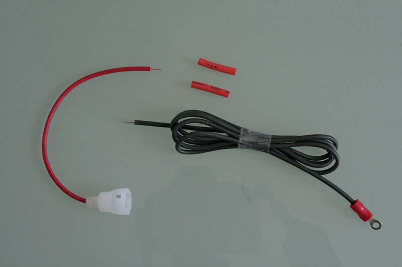
Now, cut a 75 cm piece off the provided black silkone cable. This will be the length of the supply cable. Grab a ring cable lug from the bag and get ready to crimp:
![]()
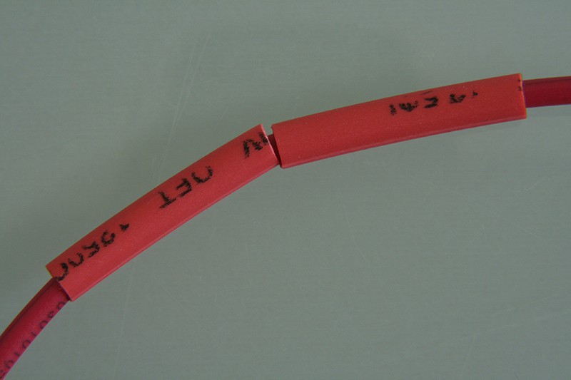
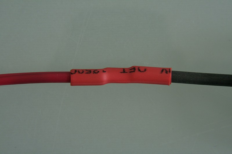
To the other end of this cable, we will now solder the other half of the cable fuse holder. Prepare the wire ends and cut two pieces from the ø 2.5 mm shrinking tube with 2 cm each for a double layer insulation.
![]()
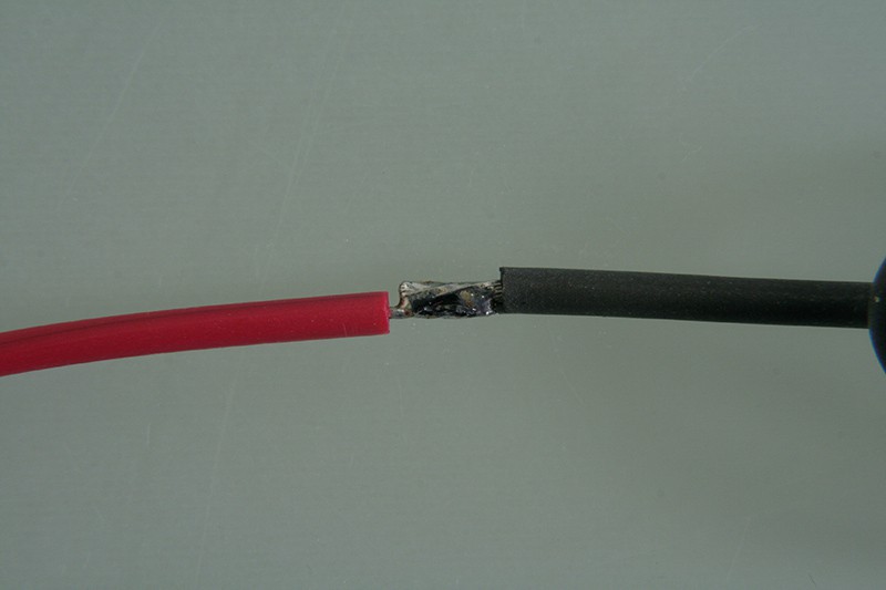
Don't forget to put the shrinking tube over the wire before soldering:
![]()
Then solder joint both ends together:
![]()
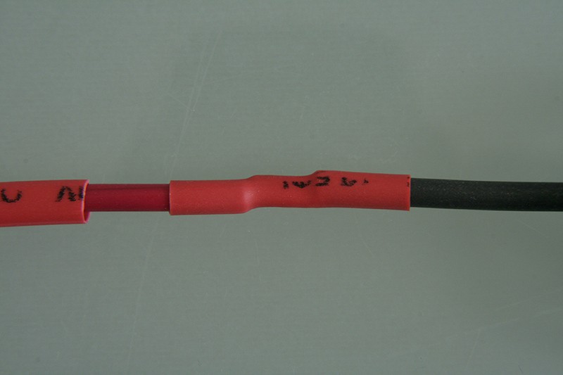
Shrink the first shrinking tube over the joint using a hot air gun or a lighter:
![]()
Then shrink the second shrink tube over the first:
![]()
Now, insert the fuse from the electronics bag into the cable fuse holder:
![]()
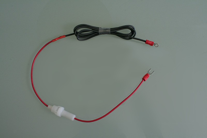
This is how the finished phase supply cable should look like:
![]()
-
5Step 5
Neutral cable
This is still wire prepping, but it deserves it's own small chapter, since the "neutral cable" differs for the 110 V~ and the 230 V~ configuration of the heated bed. As said before, the name "neutral cable" is pure notion.
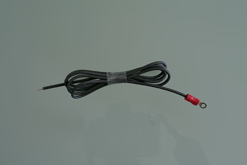
230 V~ version "neutral cable"
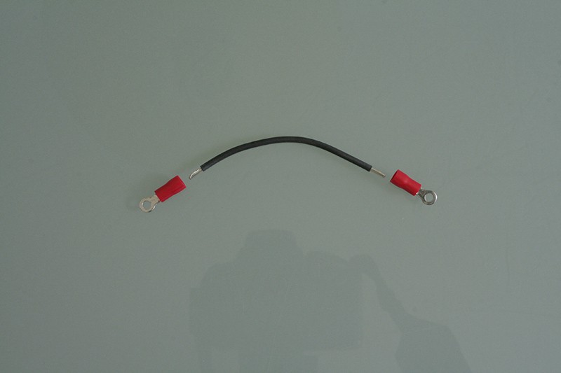
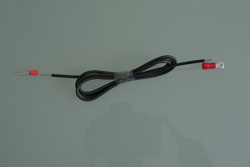
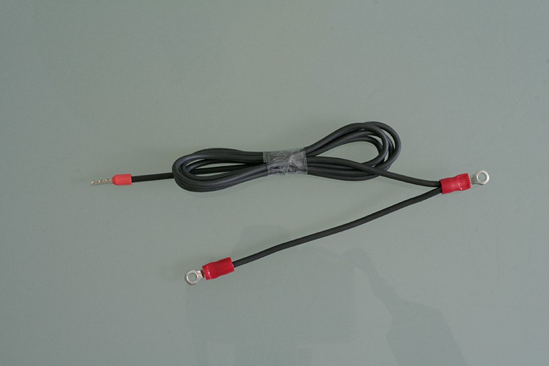
If you want to wire your heated bed in 230 V~ configuration, you'll need this "neutral cable" (110 V~ folks skip this step until 110 V~ "neutral cable"). To make it, cut another 75 cm pice from the provided black silicone cable, grab a ring cable lug and a wire end ferrule and strip the wire ends to fit the lugs.
![]()
Crimp the lugs to the wire and your 230 V~ neutral cable is finished. This is how it should look like:
![]()
110 V~ version "neutral cable"
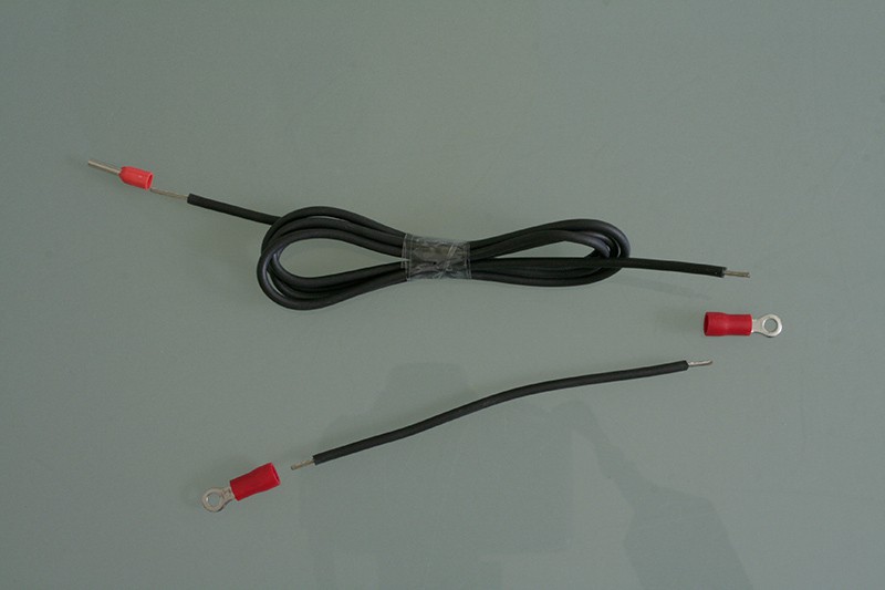
To wire your heated bed in 110 V~ configuration, you'll need this "neutral cable" (230 V~ folks skip this step). To make it, cut one 10 cm piece and one 75 cm pice from the provided black silicone cable, grab two ring cable lugs and one wire end ferrule and strip the wire ends to fit the lugs as shown below:
![]()
Then crimp the wire end ferrule to the 75 cm cable piece and one of the ring cable lugs to the 10 cm piece. The remaining ends of both wires will be crimped together into the second ring cable lug. This is how the finished 110 V~ neutral cable should look like:
![]()
-
6Step 6
Voltage Configuration
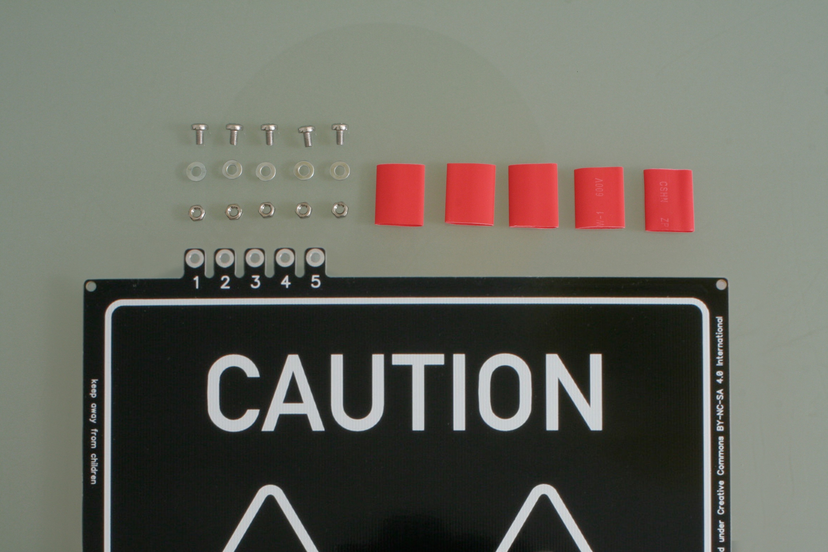
With the PCB and all the wires prepped, we can now start configuring the heated bed for the desired voltage. For this, you'll need five M3 screws, five M3 washers and five M3 nuts from the screw bag and you'll need to cut five pieces of 2 cm each from the large ø13 mm shrinking tube.
![]()
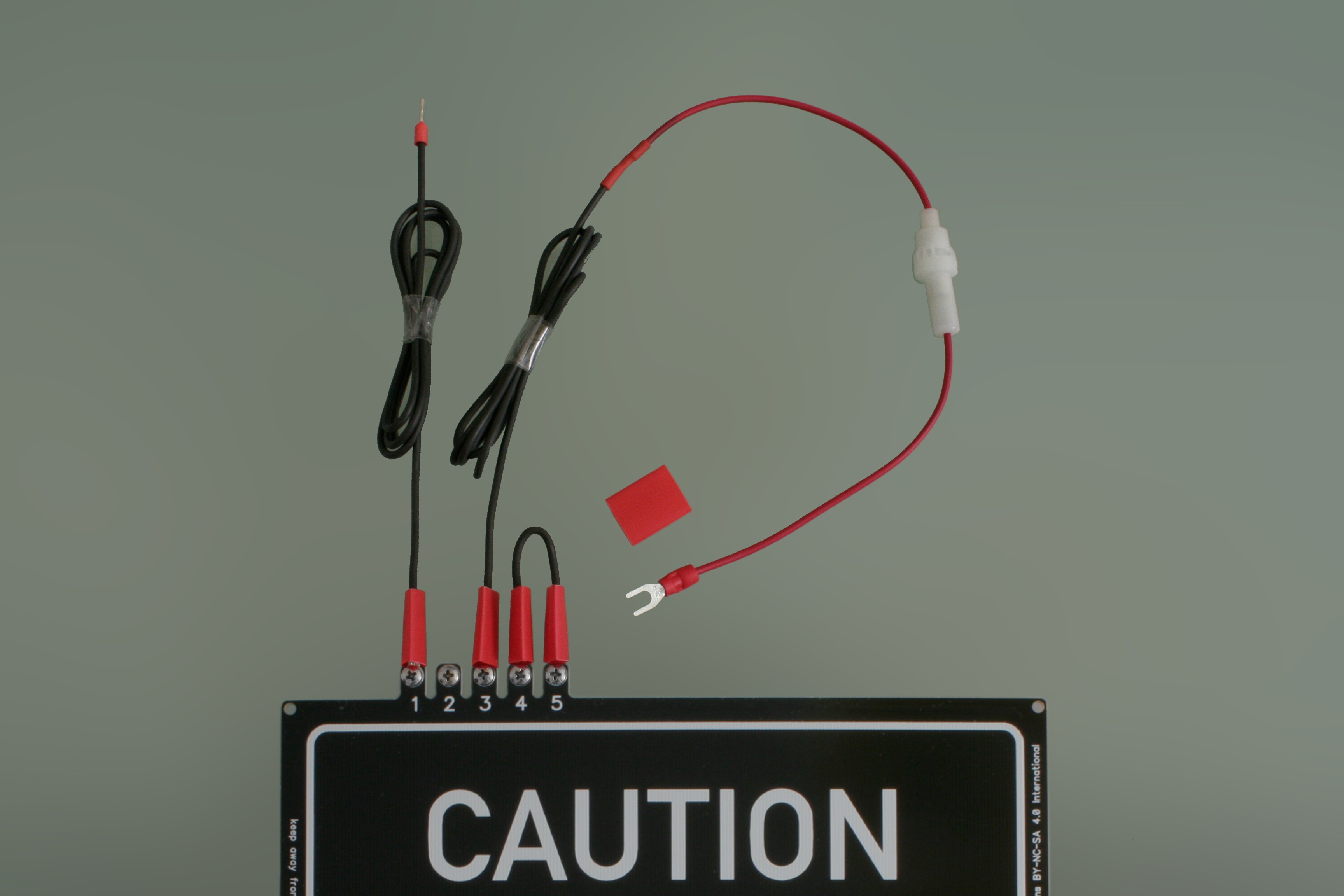
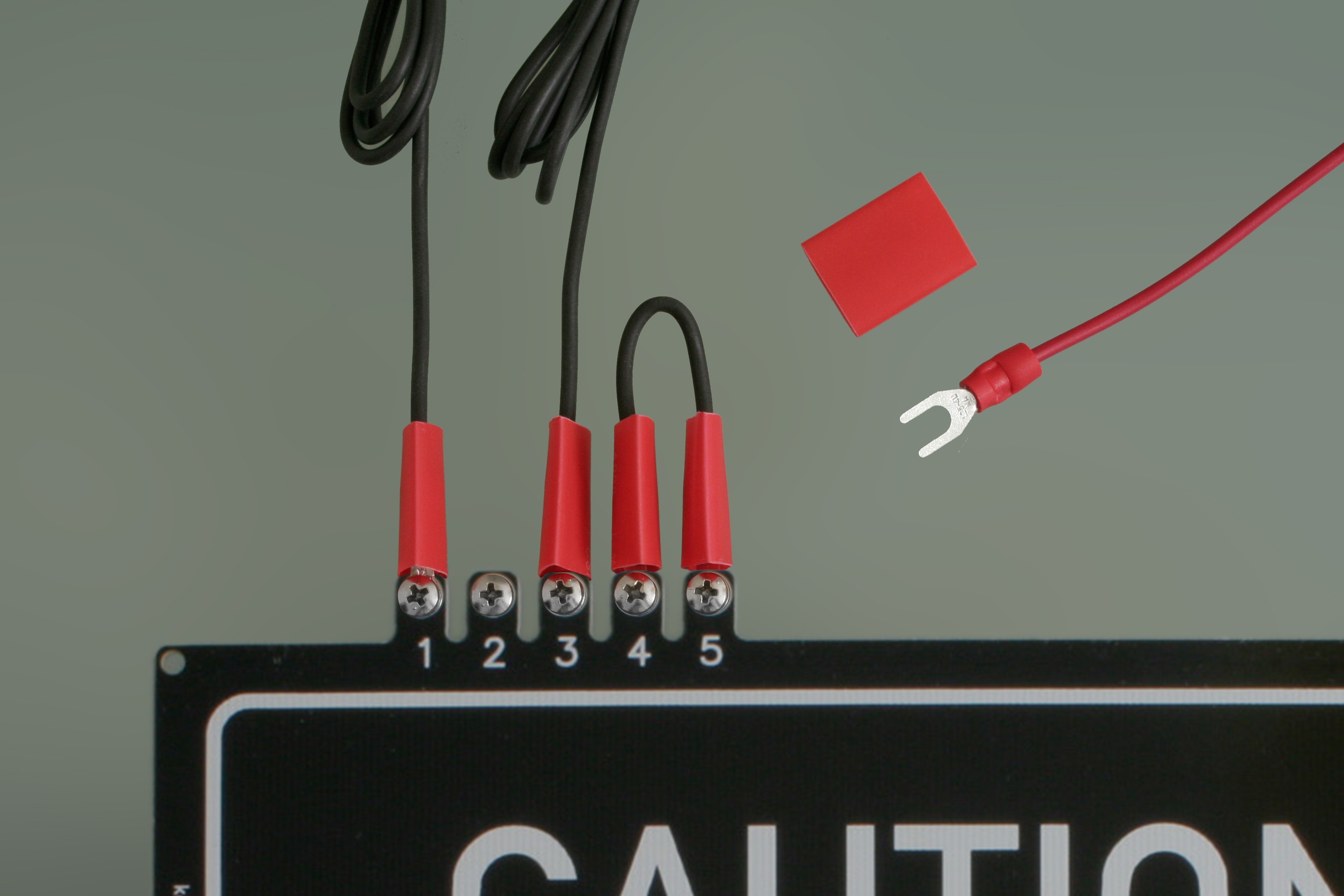
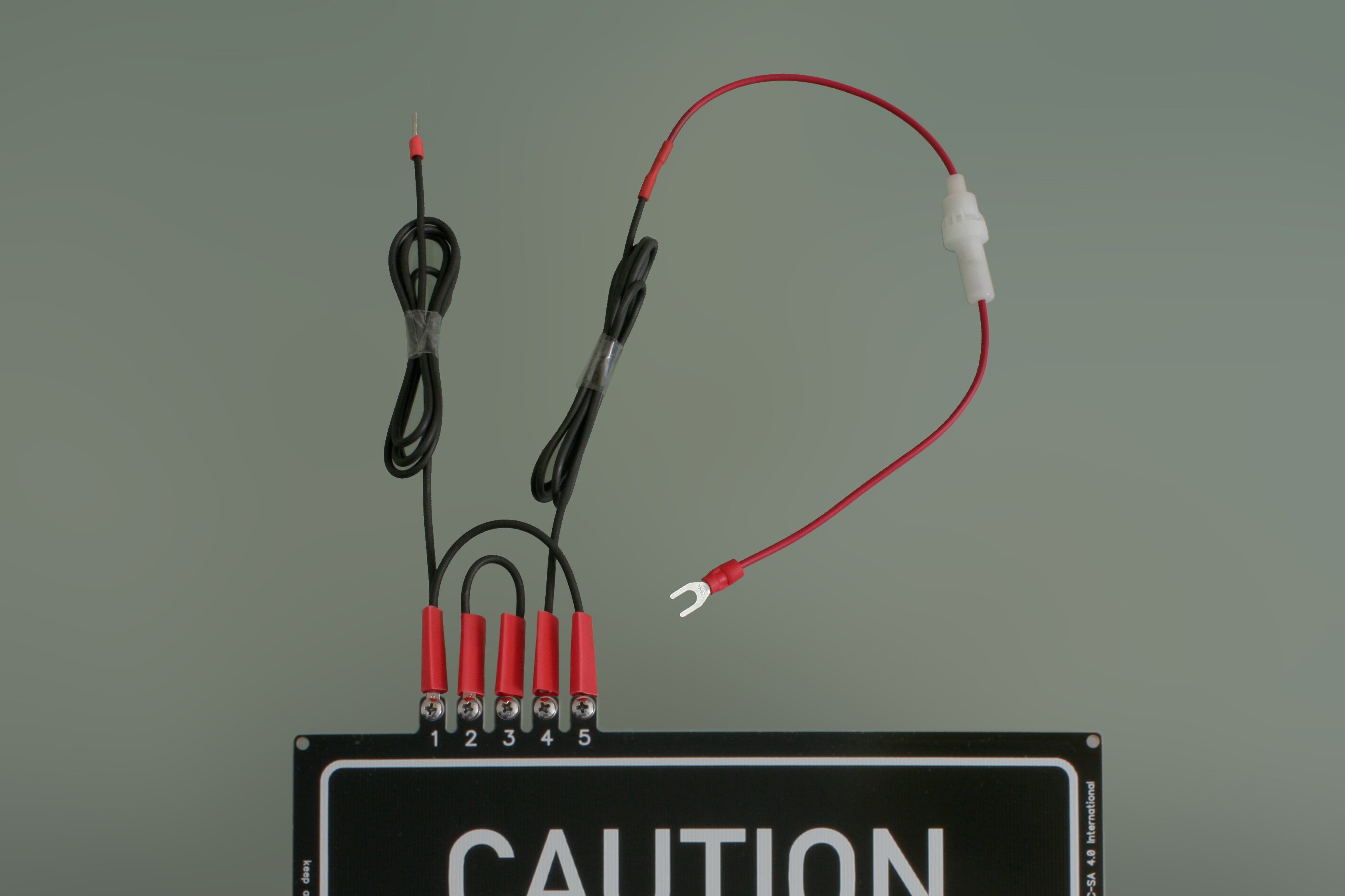
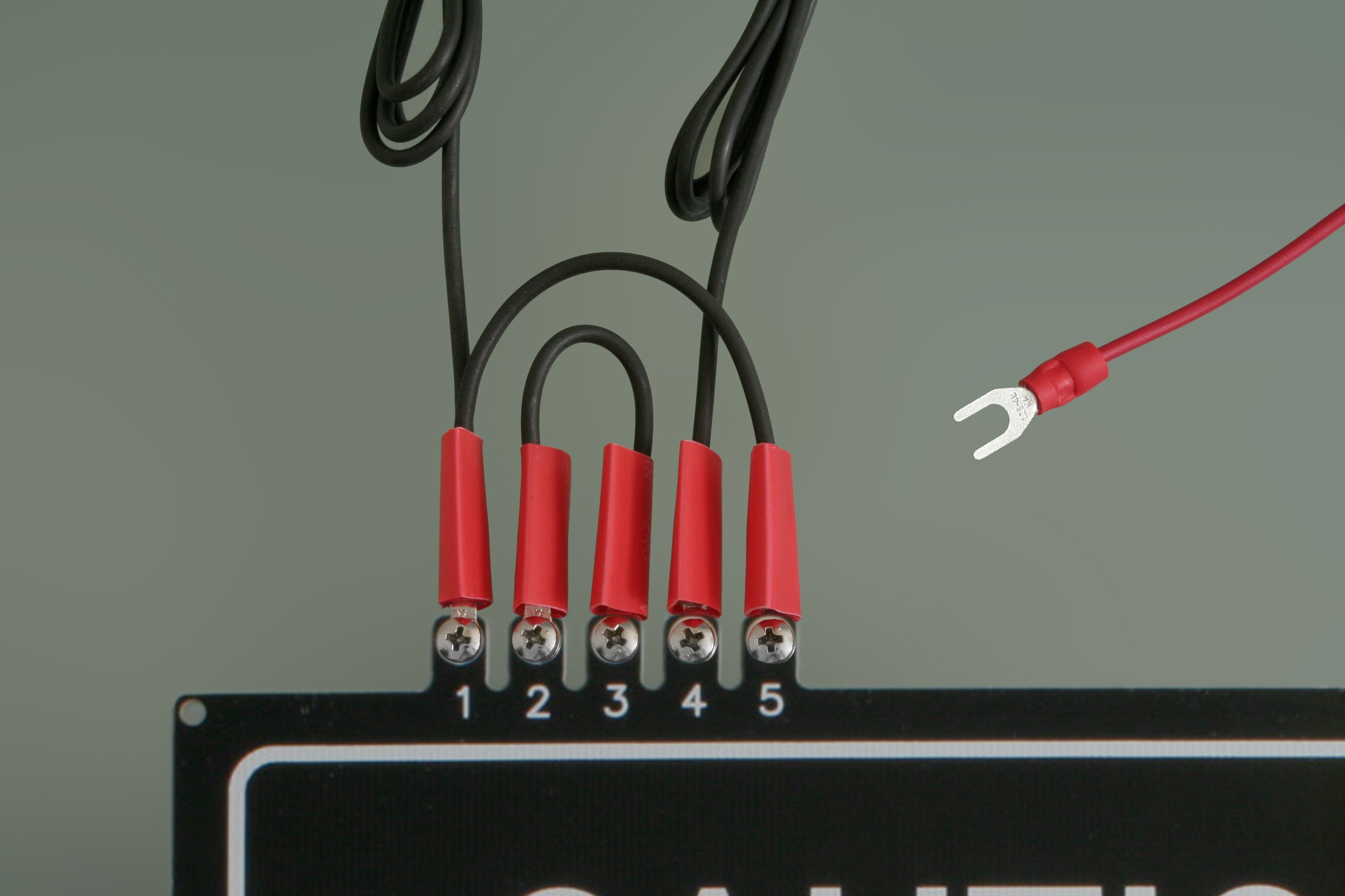
230 V~ configuration
For running your heated bed with 230 V~, you'll need to connect the prepared wires to your heated bed like this:
![]()
Connect the wires as shown to the screw terminals using the M3 screws as shown, don't forget to add the shrinking tube. Add the M3 washers between the PCB and the M3 nuts. Tighten the screws firmly, use Loctite if necessary. Also add a screw to the unused terminal, use two washers for this one. The extry screw will provide grip to the shrinking tube in the next step. Make sure the wiring is correct by checking the wiring recommendation on the bottom side of the PCB.
![]()
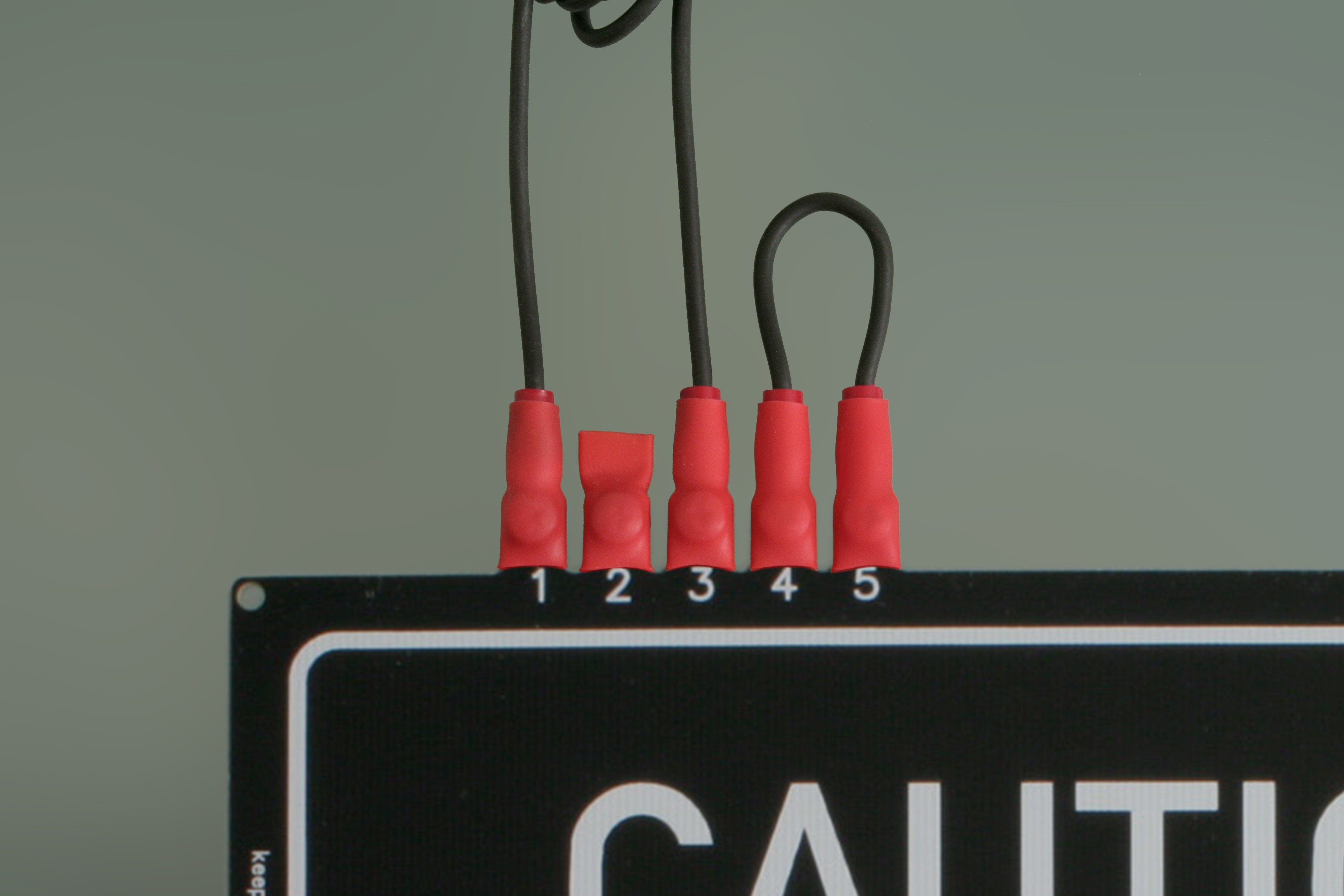
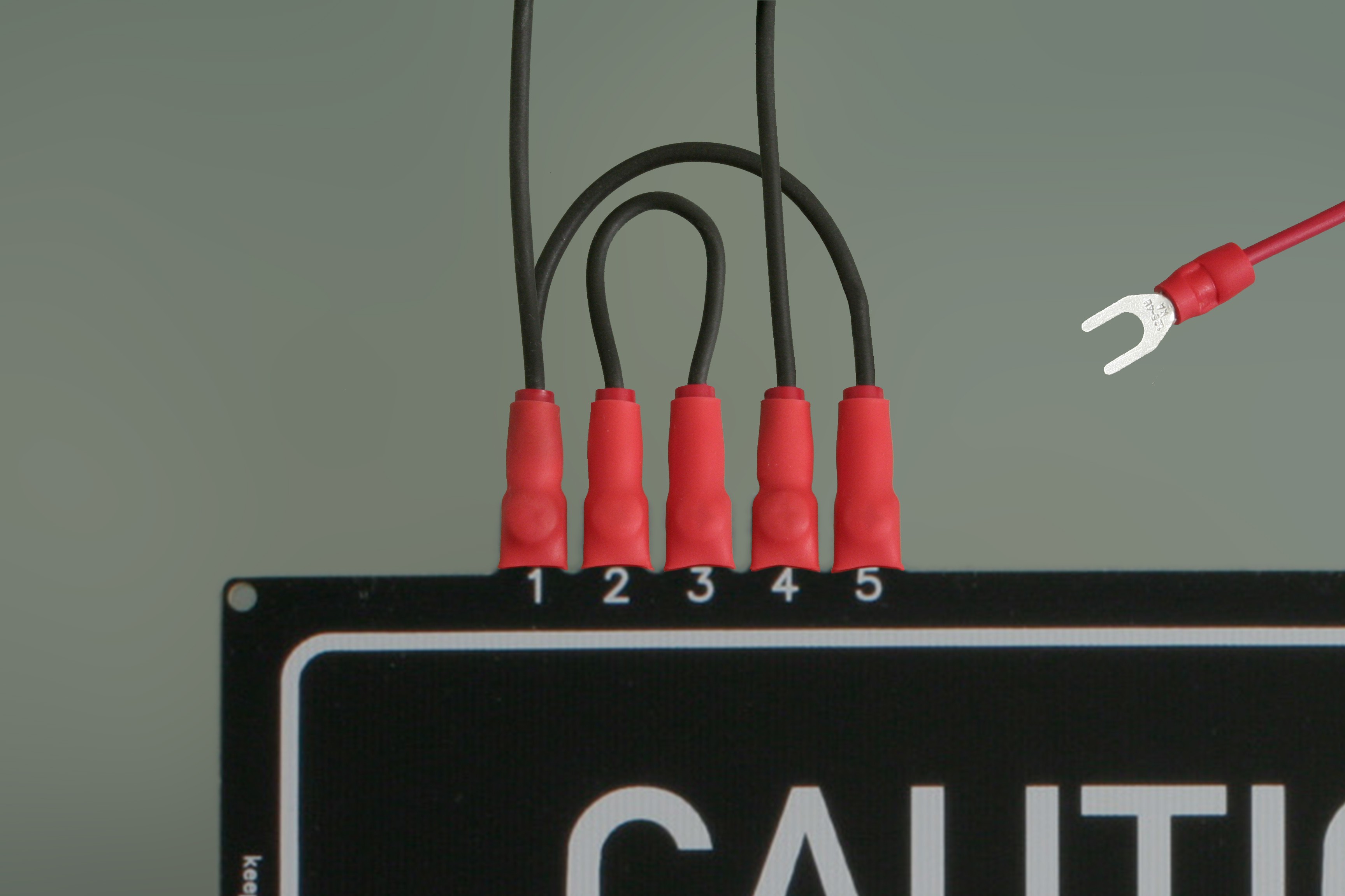
Now slide all the shrinking tubes over their screw. Heat up the shrinking tubes using your hot air gun or lighter to let them shrink over the screws and provide the vital insulation. This is how the finished wiring should look like:
![]()
110 V~ configuration
For running your heated bed with 110 V~, you'll need to connect the prepared wires to your heated bed like this:
![]()
Connect the wires as shown to the screw terminals using the M3 screws as shown, don't forget to add the shrinking tube. Add the M3 washers between the PCB and the M3 nuts. Tighten the screws firmly, use Loctite if necessary. Make sure the wiring is correct by checking the wiring recommendation on the bottom side of the PCB.
Now slide all the shrinking tubes over their screw. Heat up the shrinking tubes using your hot air gun or lighter to let them shrink over the screws and provide the vital insulation. This is how the finished wiring should look like:![]()
![]()
-
7Step 7
Solid State Relay Wiring
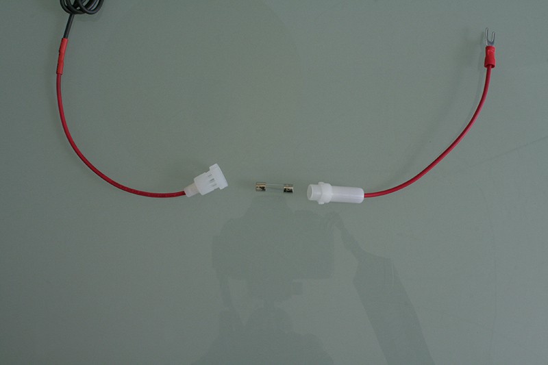
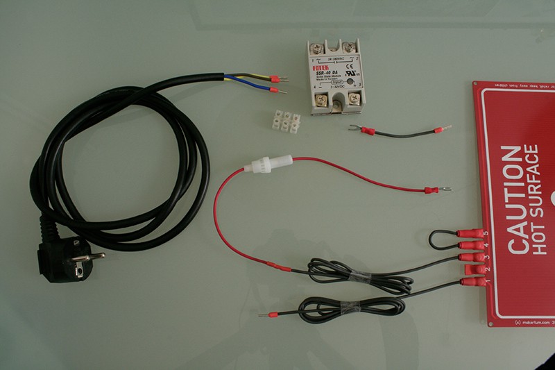
With all parts ready, we can now wire the whole thing up to the SSR. Grab the SSR, the screw connector from the cable lug bag and all the parts from the previous steps. Here's what you should have:
![]()
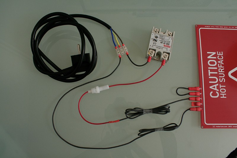
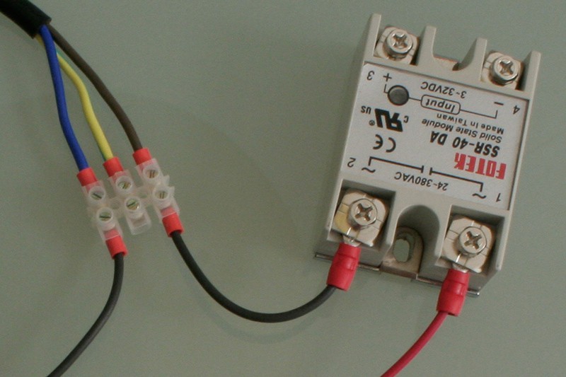
Now use the screw connector to connect the "neutral cable" of the heated bed with the blue wire of the power cable. Also, connect one of the SSRs output terminals to the brown wire from the power cable using the prepared SSR jumper. Finally, connect the "phase cable" of the heated bed with the other output terminal of the SSR. This is how it should look like:
![]()
Here's another close-up to show you the wiring of the SSR, make sure you get the colors right and don't mix up the input and output side of the SSR:
![]()
Safety precautions
Mind that those pictures are just a guidance on how to wire everything, your individual setup can require a different wiring. If your printer is from metal or has a metal housing, you should connect the earth wire (the yellow one) from the power plug to the housing and make sure that all housing parts have good conductive contact with each other.
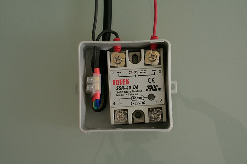
Eventually, you'll also need to put the shown wiring into a safe housing. Under no circumstances use this with your printer with the mains voltage connectors being exposed like this, as said, the shown is only for illustration and guidance.
The following IP54 enclosure is not part of the kit, but you can get them at any hardware store for a few cents. They can be considered a safe enclosure for up to 400 V. In any case, make sure you have a suitable housing.
![]()
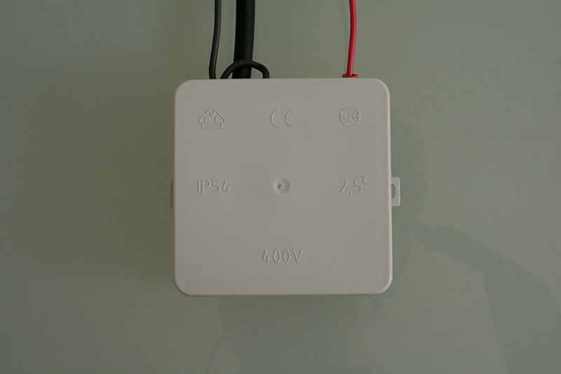
Snap goes the cap. Don't open while connected to power.
![]()
-
8Step 8
Foldback
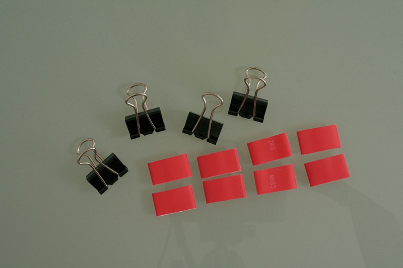
It should be obvious, but here I say it: Never, ever print directly on the mains voltage bed. I don't recommend just clamping a printing surface on it, the heated bed must be safely enclosed on the bottom side to prevent users from touching the pads on the bottom side, which may conduct mains voltage. Also, the heated bed must be covered by an insulating material on the top side, since the solder mask cannot be considered a safe insulation.
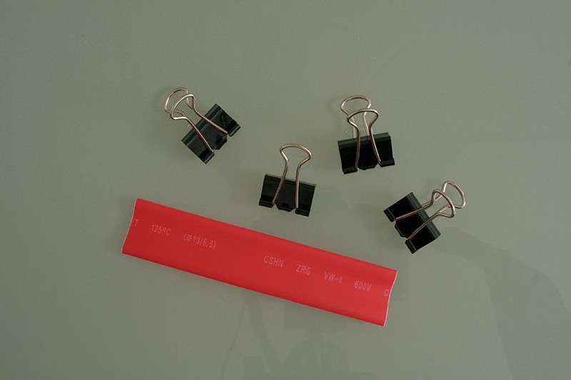
However, if you really need to use foldbacks, at least insulate them with shrinking tube to prevent them from scratching off the solder stop. This is a good hint for any heated bed.
![]()
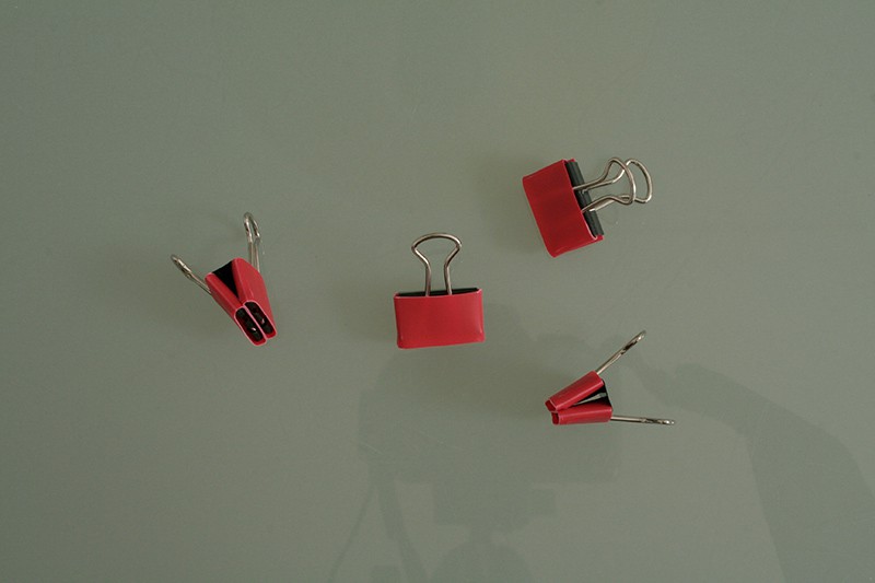
To do so, cut four pieces of shrink tube of 1.2 cm length. The exact length depends on your clamps however.
![]()
Slide them over your foldbacks:
![]()
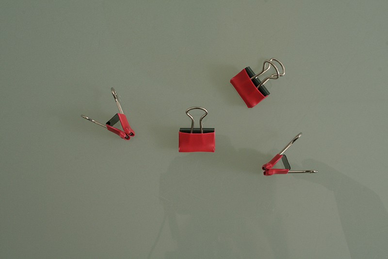
And shrink them in place. Now you have insulated foldback clamps.
![]()
-
9Step 9
Temperature control
What has not been covered in this instructions writeup is the temperature feedback and temperature control of the heated bed. However, it is beyond of the scope of these instructions to cover all possible temperature sensors, thermistors, thermocouples, adapter boards, 3D printer electronics and thermal control algorithms. This is just a short introduction, so make sure you know what you do.
Installing a thermistor
Just like the popular MK2 and further derivates of Josef Průša's MK heated, this heated bed can be used with a regular thermistor that is strapped to the bottom side of the PCB with the help of Kapton tape, thermal compound or thermal conducting epoxy glue.
Before you start, clean the bottom side of the PCB with isopropanol to get the Kapton / glue to stick well. Also, add wires of sufficient length to your thermistor.
If you use a normal thermistor, just apply a bit of thermal compound to it's head and stick it through the center hole of the PCB heated bed from the bottom side. Make sure the thermistor touches whatever printing plate you use on top of the PCB and has good thermal contact with it. Stick the thermistor in place with Kapton and make sure it stays in place.
Maximum temperature
The heated bed's recommended maximum temperature for continuous operation is 110 °C. The heated bed has been tested at 130 °C, but slight yellowing of the silk screen can occur when exposing the heated bed to this temperature for a long time.
110 / 230 V~ PCB Heated Bed
Meet the Makertum MK1, a 500W PCB heated bed that runs from mains voltage

Discussions
Become a Hackaday.io Member
Create an account to leave a comment. Already have an account? Log In.
I have difficult to understand if there is any special configuration in the firmware to use this heated bed. Very nice your tutorial of "how to assembly and mount " but nobody is telling anything about changes on Marlin. Did I just replace the bed?
Are you sure? yes | no
Just an FYI, my Marlin PID settings (when calibrated against 110C with 8 cycles) were:
#define DEFAULT_bedKp 67.61
#define DEFAULT_bedKi 13.23
#define DEFAULT_bedKd 86.40
Are you sure? yes | no