-
Kits Available Now, XXL Printing News
07/07/2016 at 08:30 • 0 commentsPure Awesomeness Available Now
The Makertum MK1 kits from the pre-production are now available on Tindie and in the Makertum shop starting at €37 or $41, which includes free wordwide shipping.
Just like in the beta-testing phase, the heated bed comes as a full-kit that contains all the parts necessary to get you up and running. The SSR is optional, just in case you already have one.
Where to buy?
Makertum Shop ![http://makertum.com/en/shop/]() recomended for EU customers
recomended for EU customers
- native payment in €
- discounts for Bitcoin and WorldcoreTindie Store ![]() recommended for US customers
recommended for US customers
- native payment in $
- pure Tindie awesomnessXXL Printing News
So, where do we go from here? Well, it's a high performance 3D printer part, but it's main limitation is still size. The problem is, that if I just scale up the size of the PCB, it quickly becomes impossible to manufacture. I get a 90% yield from my current manufacturer now, and this number will go down dramatically on even larger PCBs, while at the same time, the product becomes more difficult to ship.
IMHO, the only reasonable answer is tiling. Tiling smaller heated beds to a larger area is comparably cheap, and costs scale linear with print area.
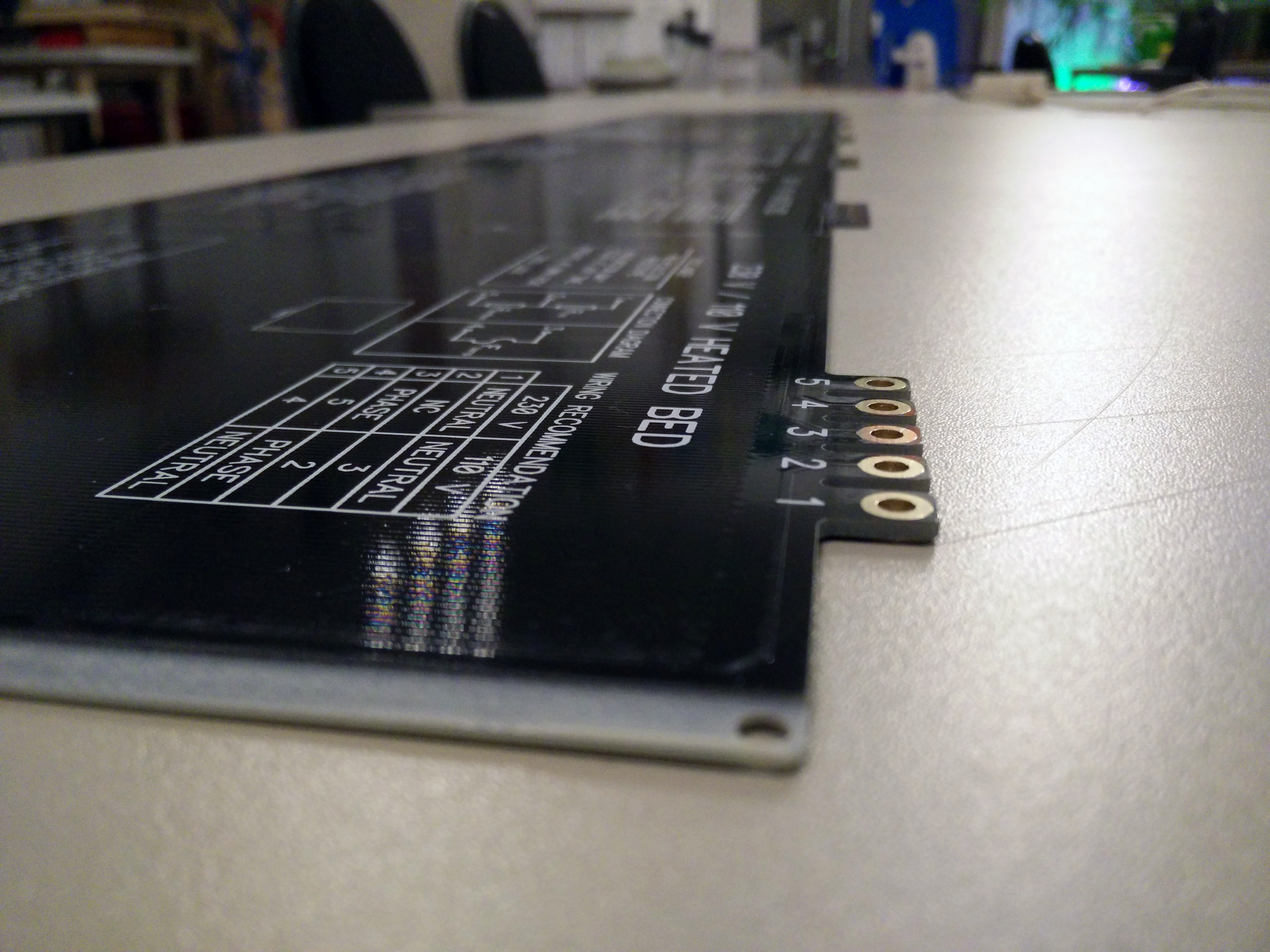
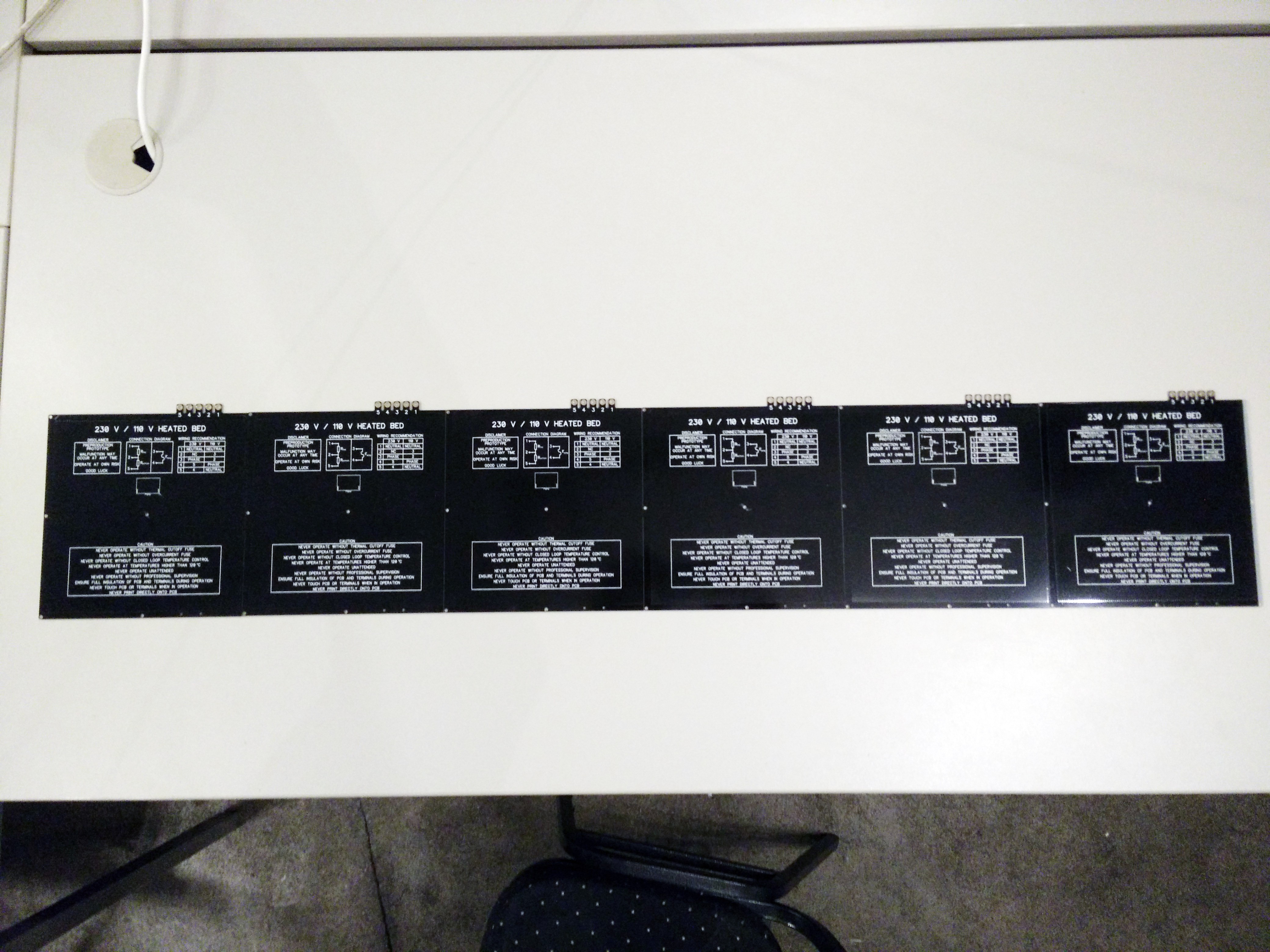
There are a few challenges to tackle, such as uniform heat distribution, temperature control, and mounting. So that's what I'm testing now. Large, tiled heated beds. Here a few impressions:
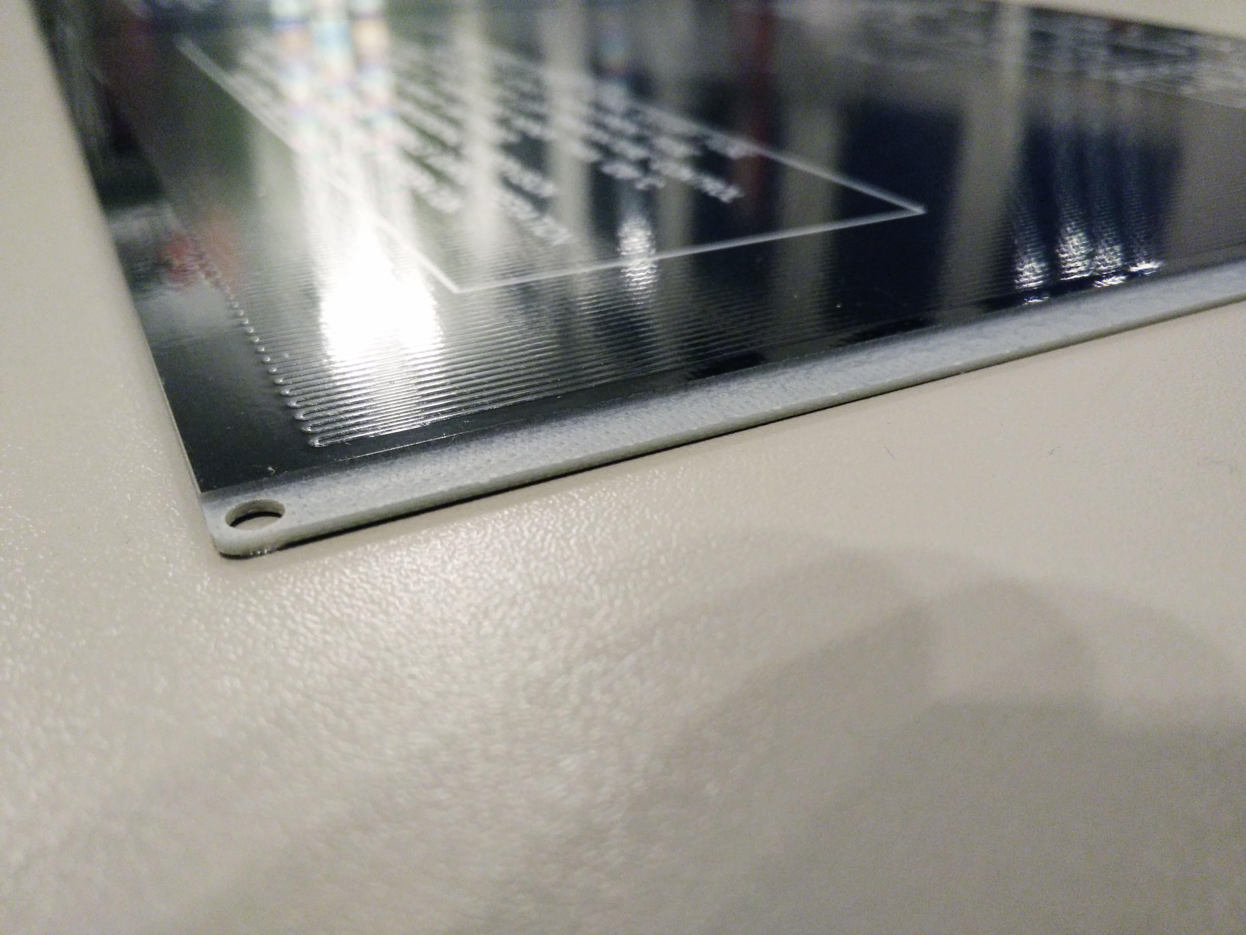
Basically, I'm trying to mill out the edges..
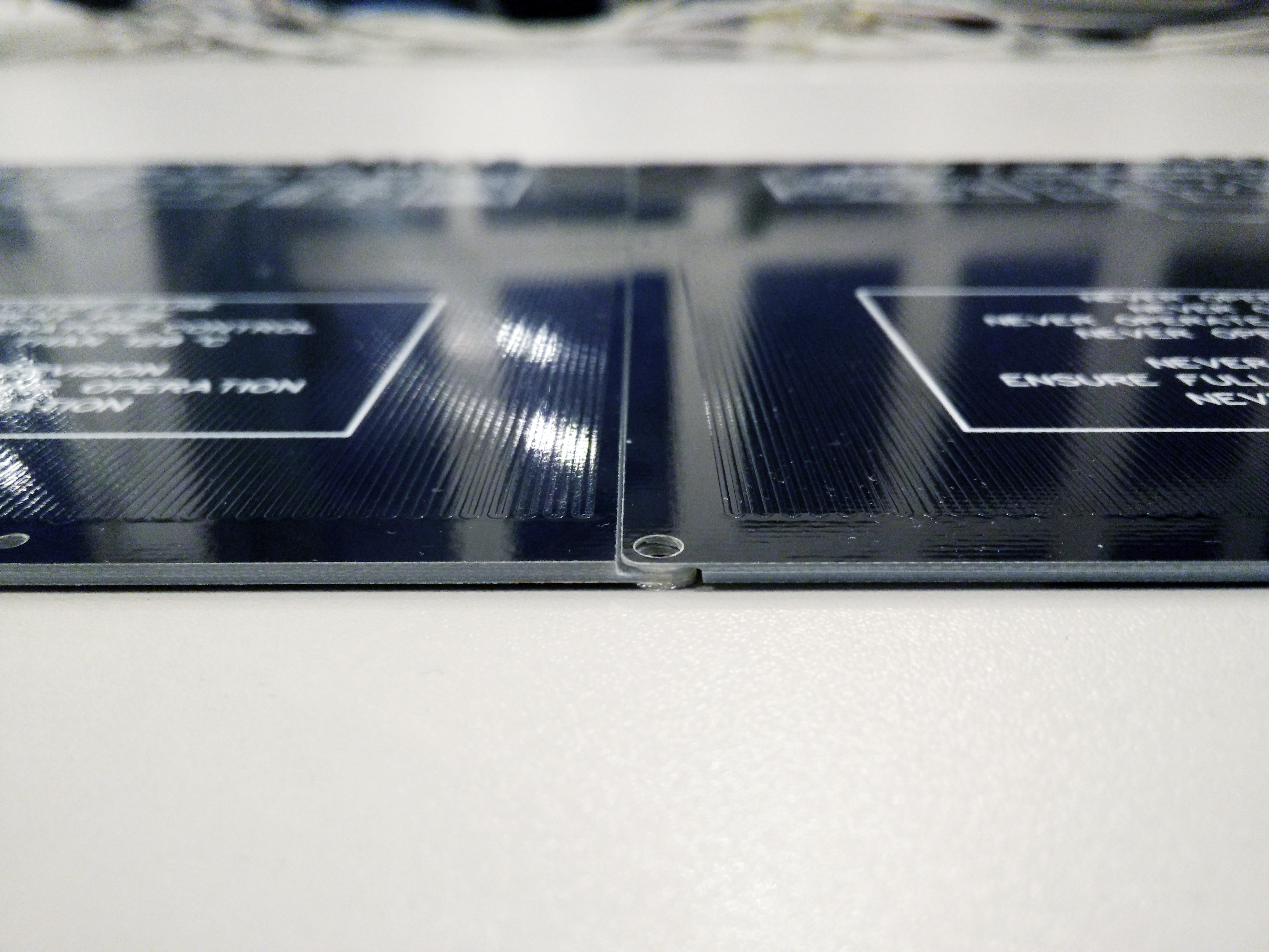
..to let them overlap with each other..![]()
![]()
The result is a large heated bed. Hackaday Prize? I'll get a Nobel Prize for this!
Of course, the layout would have to be adjusted to cover the gaps between the boards, and it would be nice if there was a power bus, as well as a bus for the temperature feedback.![]()
![]()
Print a whole leg prosthesis. In one piece. Because, why not?
![]()
-
Pre-production
06/30/2016 at 20:39 • 2 commentsGood news everyone!
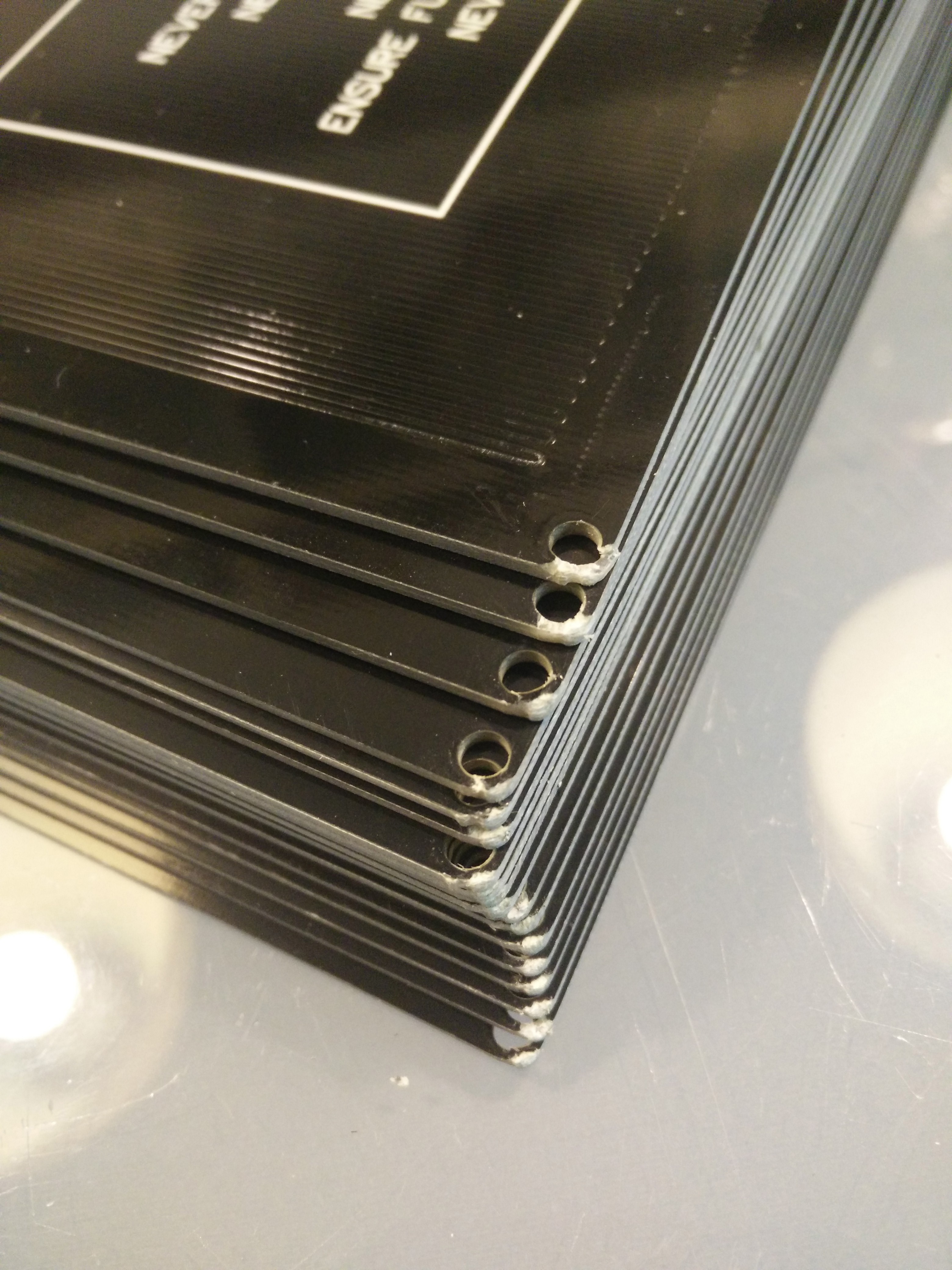
It's been a while since the last update. In the meantime, I've sent the new design off to different manufacturers and waited for the results to come back to me. Then, I received an email from Mike Szczys and started writing for Hackaday, the blog part of it. Then the results came back. Then, I threw them all in the trash. It was a pretty sobering experience. See the wall of fail at the end of the post for details.
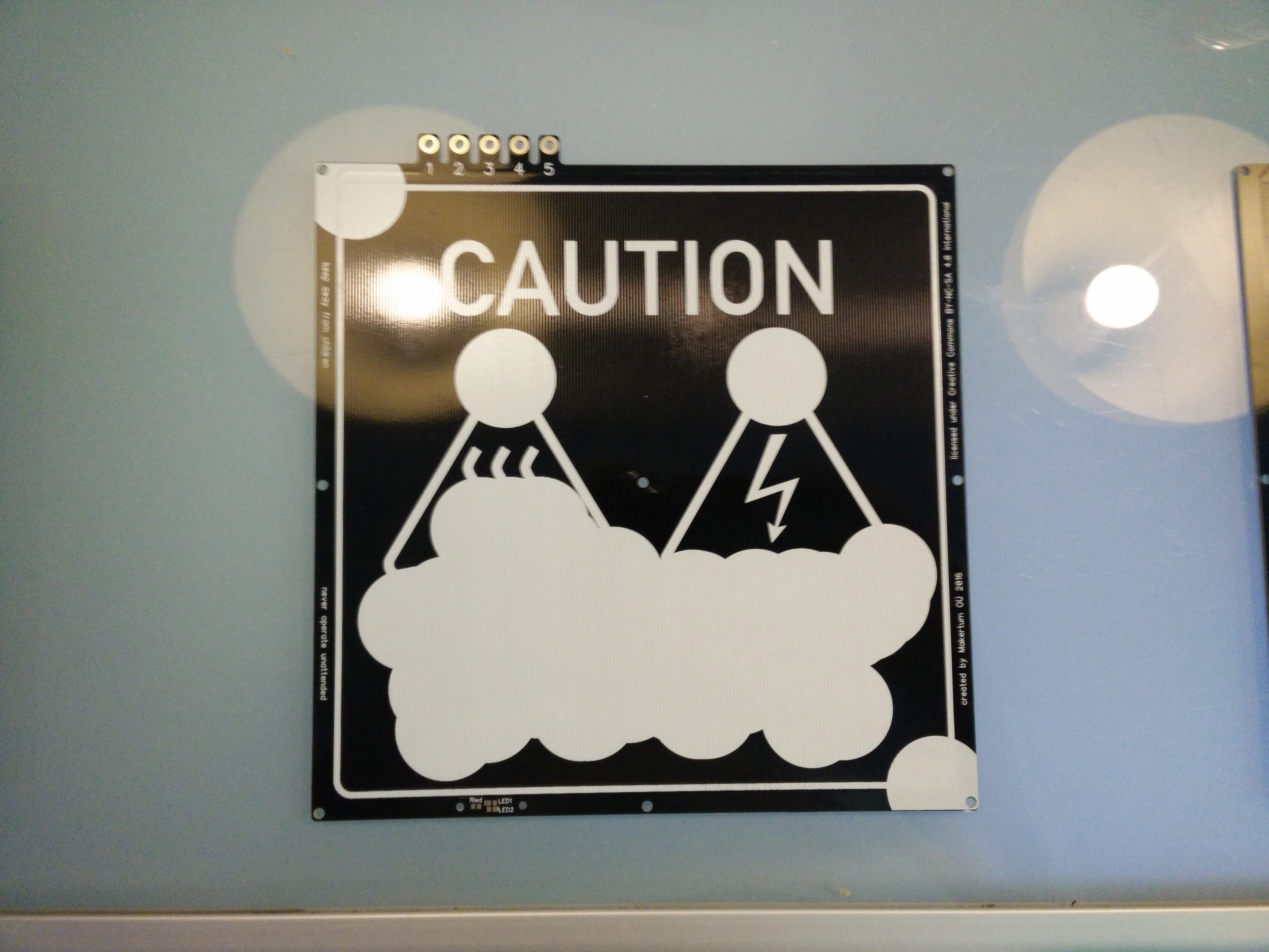
Then, I got new quotes from new suppliers. Well, it's pre-production after all, and we're happily burning money on it. Better now than later. I finally found a manufacturer that delivered beautiful boards with an acceptable yield. From this preproduction run, I currently have 50 heated beds here for testing now. I still have to do a bit more testing on them, and if everything goes right, they will be available in the shop soon.
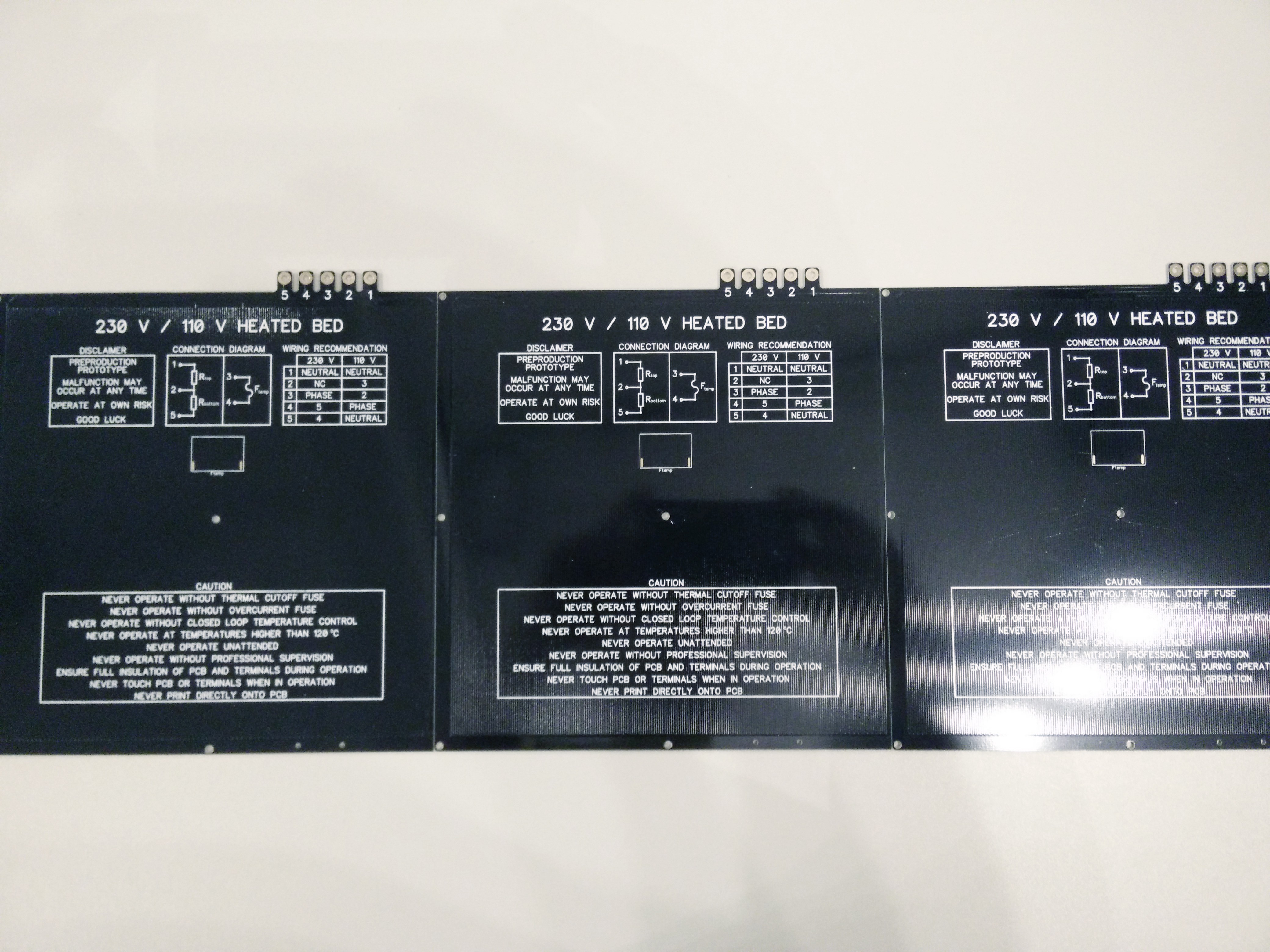
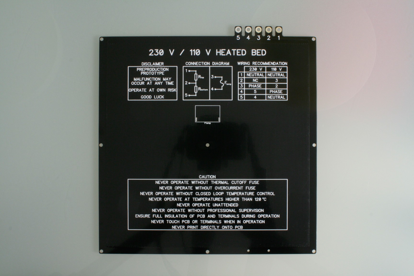
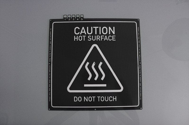
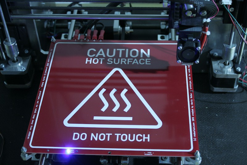
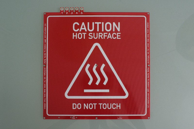
This is how they look like:
Wall of fail
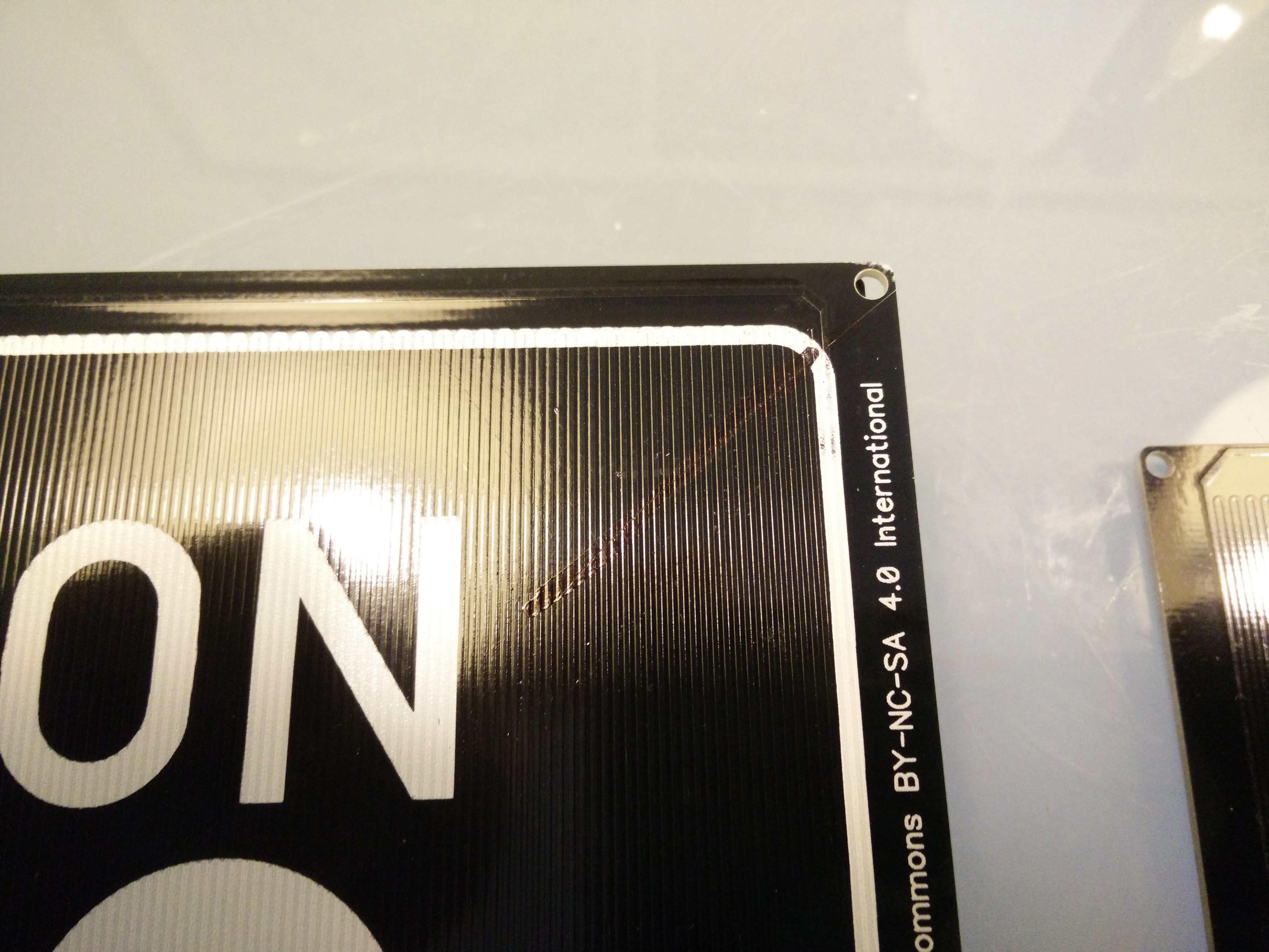
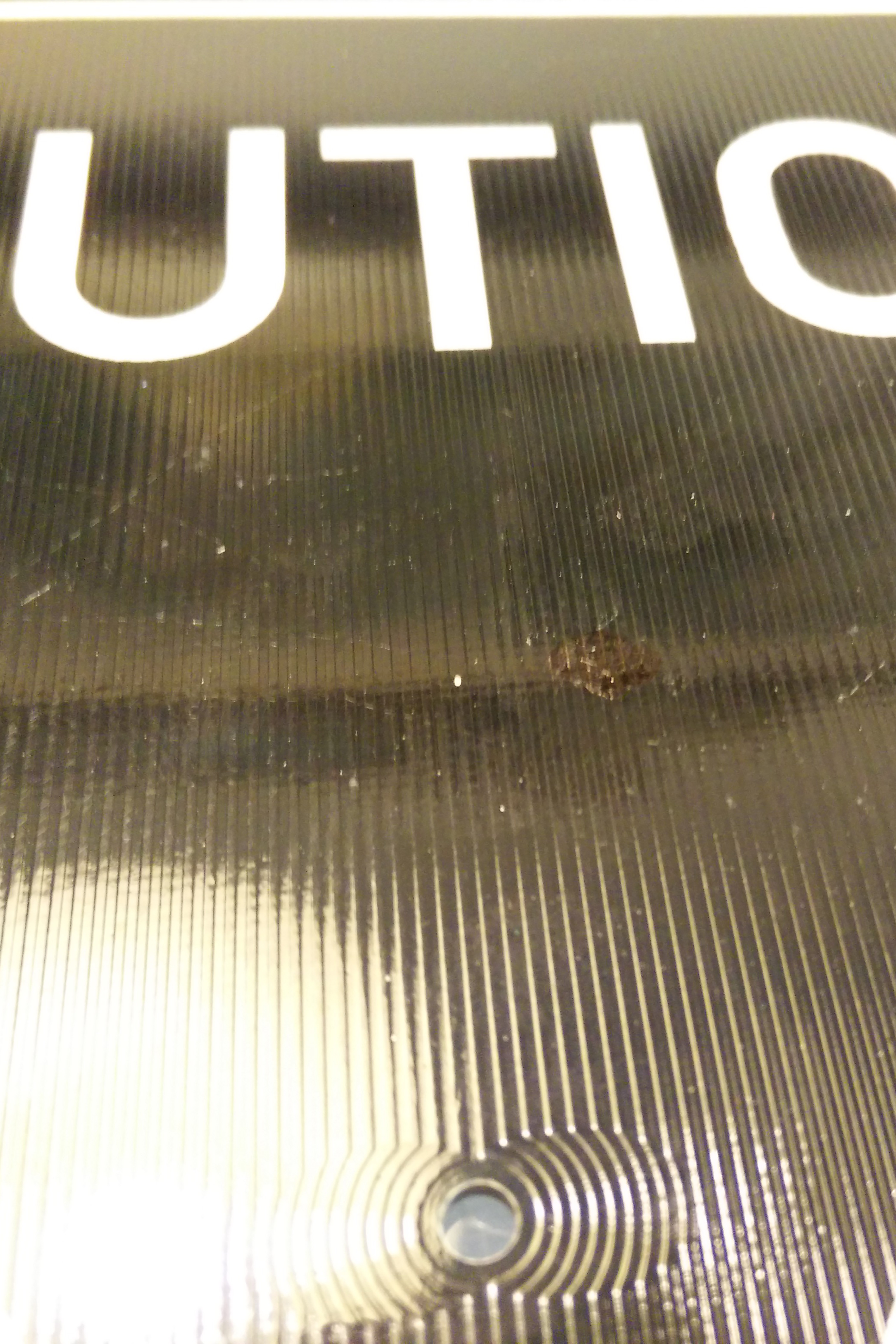
The first series of boards (the red beta test units) came from DirtyPCBs. They were awesome. I think it's worth mentioning that. When they fail, then they fail bad, but most of the time, they are simply amazing. Not so the manufacturers I tried afterwards. All of them had higher per-board prices, and all of them sucked hard. Some arrived with the Gerbers entirely misinterpreted (and yes, I quadruplechecked them), some had a weird flaky soldermask, and some just arrived virtually without packing and took serious damage. Here are some excerpts.
Packing fail
![]()
Gerbers WTF
![]()
Black marker FTW
![]()
![]()
These spots are quite common, although some runs had 50% yield due to these.
![]()
![]()
-
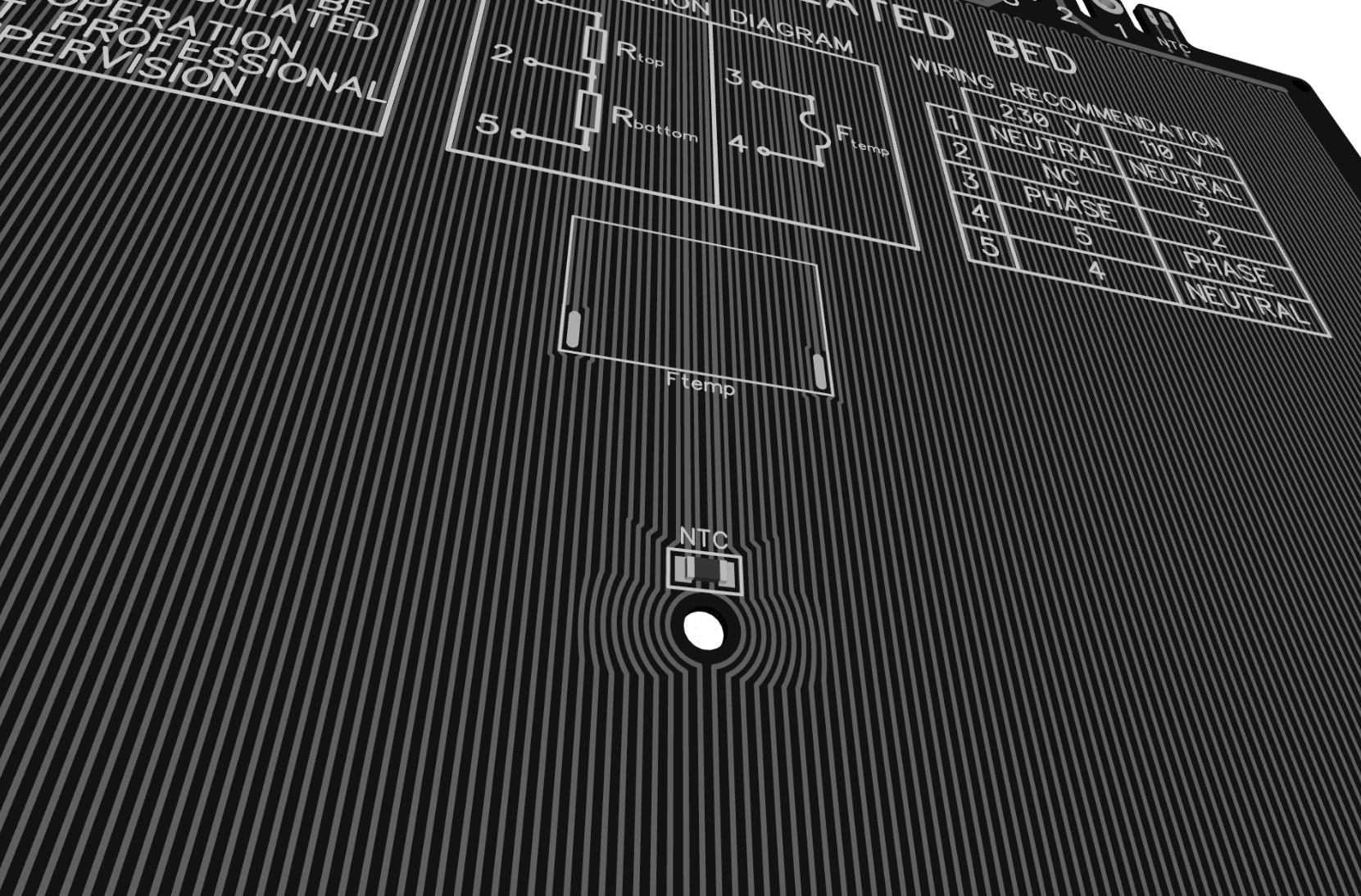
Dropping NTC pads; new silkscreen;
03/30/2016 at 14:14 • 1 commentNTC
While fiddling around with the traces to squeeze in the NTC, it became obvious that adding the NTC to the board was not the great idea I thought it was, simply because I need to maintain a proper clearance between the high driving voltage and the low logic voltage to prevent arcing.
How to not do it: Two 230 V traces between the pads of an 1206 NTC :)![]()
A friend helped me through the related norms, such as IPC2221B and EN60664, and it turns out that a minimum insulation distance of 2.3 mm would be required. Since most RepRap electronics are not sealed from touch, we have to consider a good safety margin on top of that, about 100%, ending up at 4.6 mm clearance. Of course, this large distance would also functionally affect the sensor, which should be really close to the heating traces in order to get responsive and accurate readings.
So, if you can't do it right, don't. Because of this and until I get a better idea, I will drop the NTC from the design. The NTC can be mounted and insulated in many better ways, making use of kapton or mica, so there's no also need to compromise uniform heat distibution here.
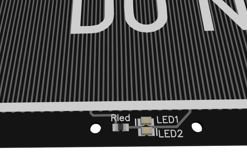
LED circuit
As said, I dropped the LED overcurrent fuse, so the double sided cover will not be required any more.
![]() New silkscreen
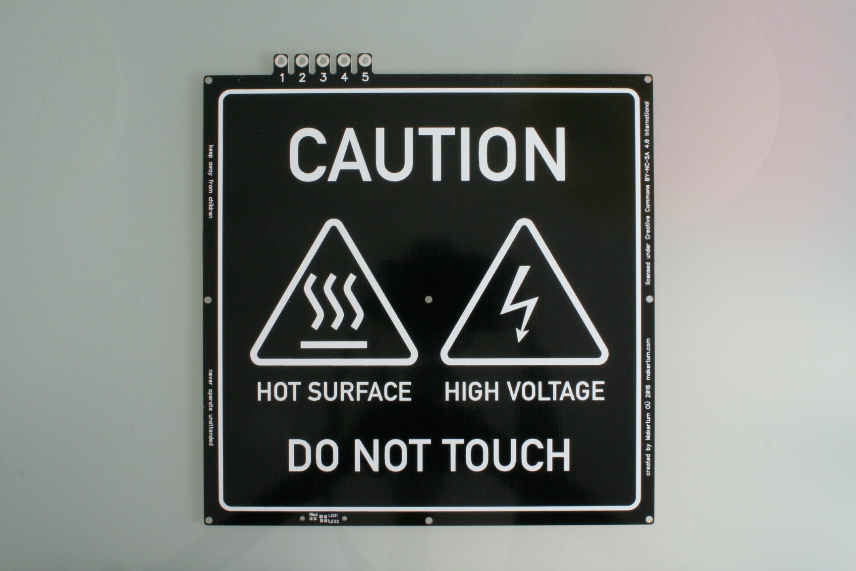
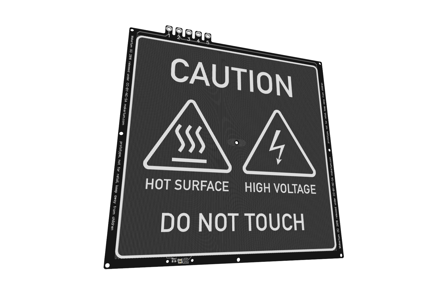
New silkscreenAlright, I know, this project log is not all that exciting :) But look at the new cool silkscreen. It has a lightening bolt on it to remind the user of the fragility of life.
![]()
-
Design changes; Approaching pre-production
03/26/2016 at 13:09 • 2 commentsWhile beta testing is still ongoing and feedback starts coming back, I also spent lots of time evaluating the overall quality of the product in a large QFD, which, together with the feedback, will result in one iteration of design changes. Hint: It's going dark. This is how it could look like (the LED will stay onboard, don't worry :)
![]()
Until now, I got overwhelmingly positive feedbacks with no serious complaints about the prototypes. However, I'm thinking of offering users more choices in terms of LED colors :) What do you think? I'd be glad to hear more opinions on this in the comments. I'f you're cool with blue LEDs, you might want to grab the last available beta testing kit :)
Design changes
Adding solder pads for NTC / thermistor
On popular request, I'll add solder pads for an onboard NTC. If possible, they will be routed to the back to some pads for the wires. I originally omitted that, since I weighted the board area more valuable to be used for heating traces, especially when they might remain unused if the user prefers a thermocouple. Apparently it looks like virtually everybody uses thermistors, and nobody uses thermocouples on heated beds.
Dismissing LED overcurrent fuse
It has been pointed out to me by several engineers from the beta-testing group that the Picofuse which prevents the LED from overcurrent in case of broken heating traces is overcautious, especially since the corresponding failure scenario is highly improbable and would result in a fried LED at worst. Dismissing the fuse also allows for a single sided and more streamlined LED cover.
New board color: Black
The next generation of boards will have a black solder mask. I noticed potential quality issues with the red soldermask, which always tends to get a shade darker when reflowing and generally with time. Heat accelerates this process, and I guess users would prefer their boards to look the same all the time. Using black solder mask solves this.
Pre-Production
Once the design changes are implemented, I'll approach pre-production. I found a PCB supplier, who showed interest in the project and is willing to help me a bit with pre-production, which is usually frighteningly cost intense, simply because the setup cost will be the same as for a large batch but distributes only over a small batch.
-
Beta testing is going on right now
03/13/2016 at 19:36 • 0 commentsWith only few boards left in the Makertum MK1 beta-stock, testers from US, UK, Haiti and Germany have now taken on the task to test the hell out of the prototypes from the beta production batch.
Some are already still prepping their wires, others are already printing. Stefan from Hamburg has completed his fresh Proosha IIIo 3D printer build with a Makertum MK1 and is sharing his printing experiences in a live stream right now.
AstroPi case timelapse:
Heart gear timelapse:
And also @BPop has his board up and running, sharing a stream for us of a cool project beeing printed:
Thanks to all testers and happy printing everybody!
-
Beta testing phase has started!
02/14/2016 at 15:44 • 0 commentsYay!
Beta testing has started, in fact, the first testers have already installed theirs and print diligently @Attraktor Makerspace. There are still enough available to send out. To simplify the process of getting one, I setup a little webshop in my blog.
-
Beta testing about to start shortly
02/10/2016 at 10:48 • 0 commentsGood news everyone: Eventually everything came together, the PCBs, the electronic components, the machining of the plastic parts, and the writeup of the assembly instructions, so the beta testing phase will start soon, possibly by February, 15th 2016.
Update
The hardware kits are now available here!
The beta testing hardware kit
PCB (top)
parts and electronics
PCB (bottom)
shrinking tubes
About beta testing
In the beta testing phase, I'll give out 15 hardware prototype kits to interested beta testers. Beta testers are kindly asked for a contribution of 39 € (incl. SSR) or 32 € (w/o SSR) plus shipping to obtain a hardware kit. I know that's something you don't see when beta testing in the software world, so to smoothen things a little, beta testers will get a 50% discount on a PCB from the final production line of the heated beds.
Who can beta test?
You need to own a compatible 3D printer. Besides that, everybody with sufficient knowledge about mains voltage electrical wiring and mains voltage safety precautions can take part in the beta testing. However, you'll have to agree to a legal liability disclaimer that leaves you with the full responsibility of all your actions and all the outcomes when testing the prototype.
How to get in
You can now order the kit here.
-
PCBs, dirty PCBs, and statistics
01/14/2016 at 16:31 • 0 commentsOK, you can't really do good statistics on a batch of 20 units. BUT I recently tested all the received boards I had manufactured from dirtypcbs.com for resistance and functionality, with interesting results ;)
Yield
5 of the 22 boards I received (20 were ordered) arrived defective. I contacted dirty for the issue, and they refunded me for 3 boards (since i ordered 20) within a day. The defects are kinda interesting, since they seem to be were similar, close to identical on all defective PCBs. Here are some:
![]()
Resistance variation
The rest of the boards was fine, and I could measure the resistance of them:
min average max Rtop 61,1 69,4 78,5 Rbottom 58,4 67,86 90 Rtotal 124,4 137,28 160,1 Ptotal @ 230 V~ 330,4 387,4 425,2 There resistance varies about 30 %, and even though this is a lot, for any normal PCB layout this wouldn't be an issue. Since the resistance of the traces simply defines the maximum power output of the heated bed, they're perfectly useable and a good proof of concept.
Small quantity prototyping
If I would have let the prototypes be made with a german board house, I would have paid about double the price, since even though the boards itself are about 4 times cheaper from dirty, the shipping of the large boards eats up most of it.
If I'd do this again, I'd probably use the german board house from the start. Even though I got a refund on the failing boards, shipping is not refunded, and somehow I lost my trust in their e-test ;) However, high-RPM prototyping services like dirty (or similar) chew through individual small quantity orders at an amazing rate and for an incredible price, they're still the best for their 5x5 protopack.
Manufacturing
For preproduction and final manufacturing I'll work with a high reputation PCB house from Germany I've had good experiences with in the past. I've already received quotes from them (and others), and given enough interest in the board, maybe this project will get eventually get there.
-
milling LED covers
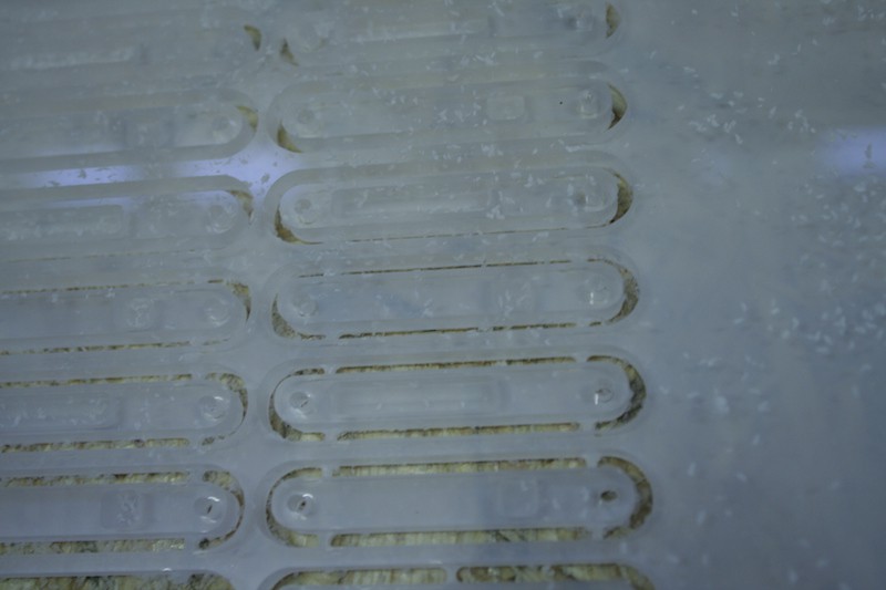
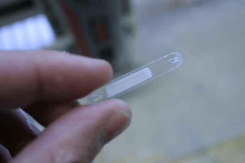
01/14/2016 at 12:28 • 0 commentsYesterday, I was able to mill the polycarbonate LED covers for the heated beds on our mill at Attraktor makterspace. They turned out way better than I hoped. The necessary screws and nuts haven't yet been delivered, but once they arrive, the parts for the first beta test kits are complete.
Cutting polycarbonate
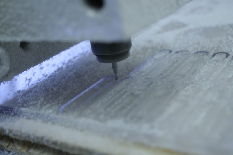
Polycarbonate is a tough and temperature resistant material and can be processed similar to wood. Large cutting teeth on normal and circular saw blades usually give good results. On the mill, you'd probably use a not too small single tooth acrylic or similar milling bit.
But those LED covers are quite tiny and I wanted the finish of the milling pockets as nice as possible. Since our mill doesn't feature a tool changer, I also wanted to mill them all in one go, which means the milling bit cannot be larger than the small screw holes (ø 2.2 mm). So I contacted the people from vhf camfacture to help me out with the right milling bit and parameters. They're very dedicated and supportive people and their unique milling bits are worth the money. Eventually, a ø 2 mm polished flute single tooth milling bit was used.
I had to experiment a bit with the right size of the attachment bridges. Polycarbonate is quite tough, so it definitely needs strong bridges, however, they are also hard to remove.
So, that worked. I was in a hurry and later on found the photo below came out blurry, but I'll soon post better pictures of the completed kits anyway!
-
comparing power consumption I
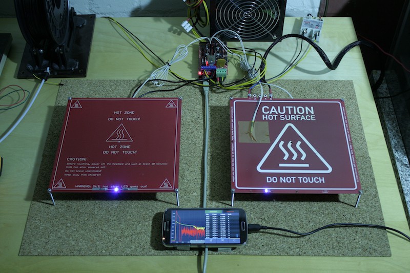
01/14/2016 at 11:35 • 0 commentsI wondered how the power consumption of the mains voltage heated bed compares to the MK2 while holding a certain temperature, assuming that the PSU will cause significant losses. However, not having two trusted electricity meters at hand, I tried it with a pair of OWON B35T bluetooth multimeters. The csv-export functionality of the app is flawed with bugs, so well, it did not work. Also, I suspect some of the readings were bad.
I will have to redo this, but however, I was able to capture the readings for full-on and idle, and they're still interesting.
The setup
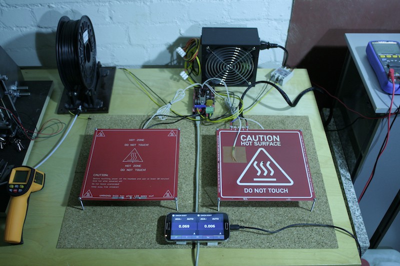
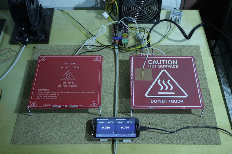
I wired the MK2 in default configuration, with the heated-bed power rail of the RAMPS 1.4 powered through the PSU shown in the photo below. The other power rail of the RAMPS 1.4, which powers the Arduino and logic is powered by another PSU that is not seen in the photo since it belongs to my 3D printer. This way, I ensured that the logic power consumption does not influence the measurement.
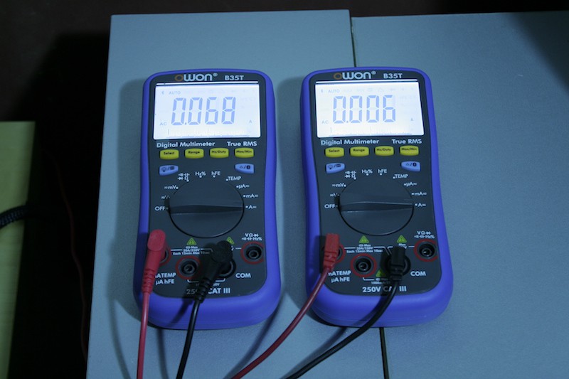
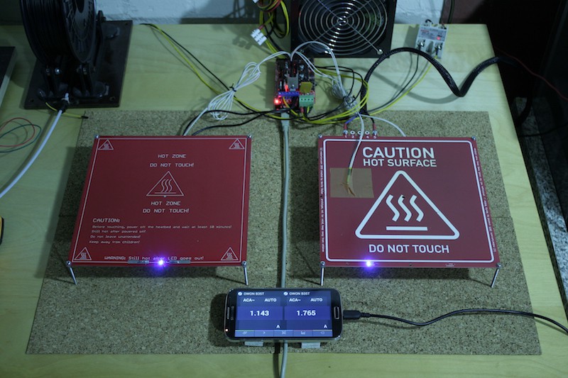
The current that goes into the above PSU and eventually powers the MK2 is shown on the left multimeter, the current that goes through the SSR and eventually powers the mains voltage heated bed is shown on the right multimeter. Since both are attached to a common 230 V~ mains line, I can compare the power consumption, even if (lacking a third multimeter for measuring the mains voltage) I don't know the power consumption exactly.
Idle
The idle power consumption is not surprising, since the PSU has the fan spinning and has to maintain some idle current on all its power rail, it must consume more power than an open switch.
Turns out the PSU draws about about 0.69 A, which results in an idle power consumption of about 16 W. The mains voltage heated bed is very savy here, since it's just off, but the SSR appears to let through a small idle current of 6mA. This idle current is suspiciously high, I expected this to be only a few µA. Another reason to redo the measurement: It's a potentially crappy multimeter, maybe just a bad reading.
Full-on
The full-on current surprised me a bit. Even though we are comparing a supposed 120 W heated bed to a 400 W heated, the current draw of the 400 W heated bed is only 54 % higher than the current draw of the MK2. Which raises the question of how much power is actually lost in the PSU. I will probably have to do some more measurements on this matter, measuring output current and voltage of the PSU as well. Eventually, the MK2 consumes 260 W of electricity through the PSU, while only half of this reaches the bed in form of heat.
Maintaining 100 °C (measurement failed)
As said, this failed. I wanted to graph the data of current consumption of both boards over a period of time while they would maintain 100 °C, but the CSV export of the data failed. I also couldn't get steady readings from the app for the mains voltage heated bed. The first problem is a bug in the csv-export of the OWON B35T smartphone app, and the latter is just because multimeters are not electricity meters and their true-RMS window is just to small to capture enough half waves from the SSR. On the smartphone app you can spot a yellow graph (MK2) and a red graph (mains voltage heated bed). The yellow one is ok, but the red one's just too noisy. I also didn't take a better picture of the graph since I expected the csv export to actually work. I'll try better next time :)
110 / 230 V~ PCB Heated Bed
Meet the Makertum MK1, a 500W PCB heated bed that runs from mains voltage
 Moritz Walter

 recommended for US customers
 New silkscreen
 PCB (top)
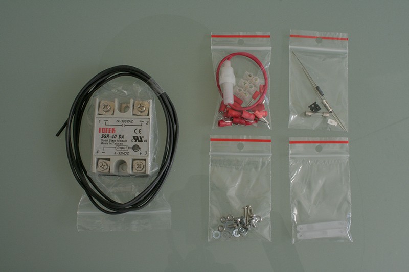 parts and electronics
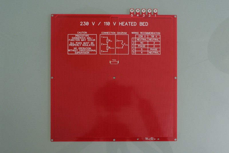 PCB (bottom)
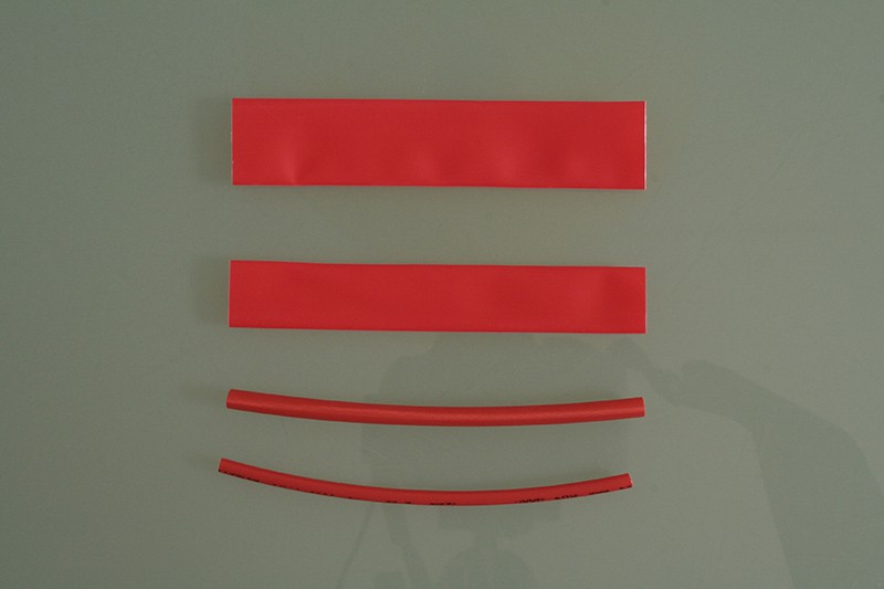 shrinking tubes