-
It's finished!
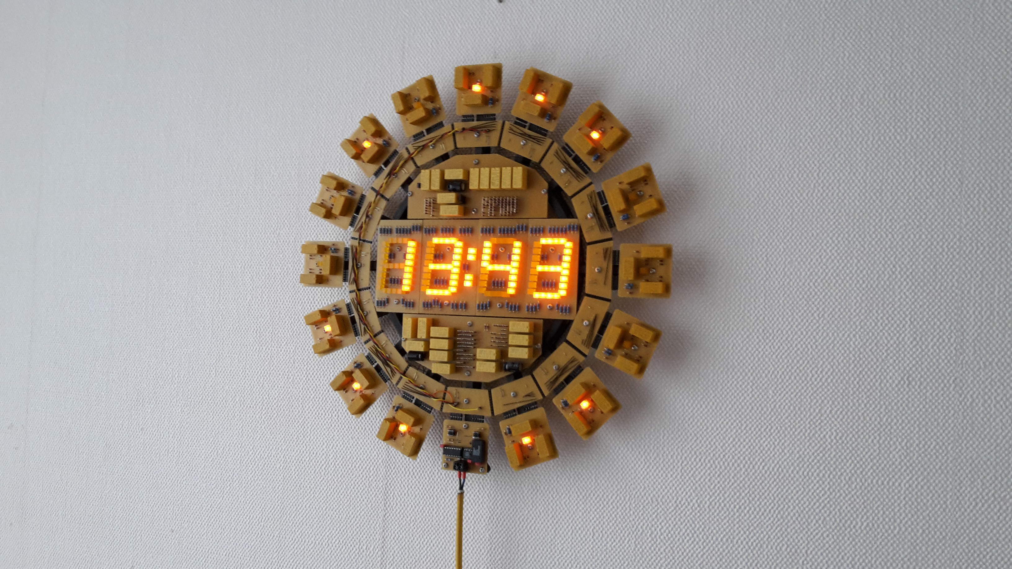
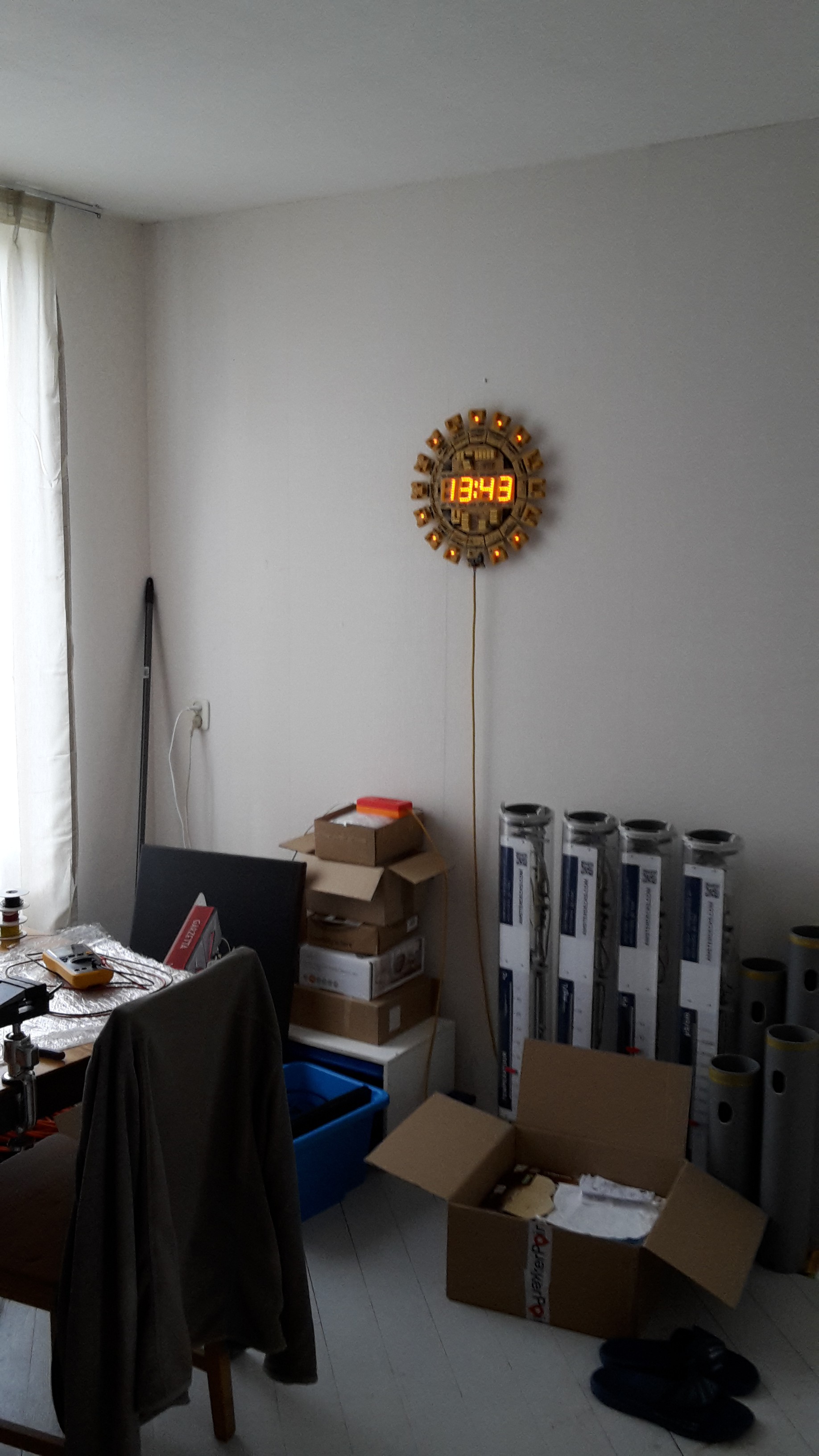
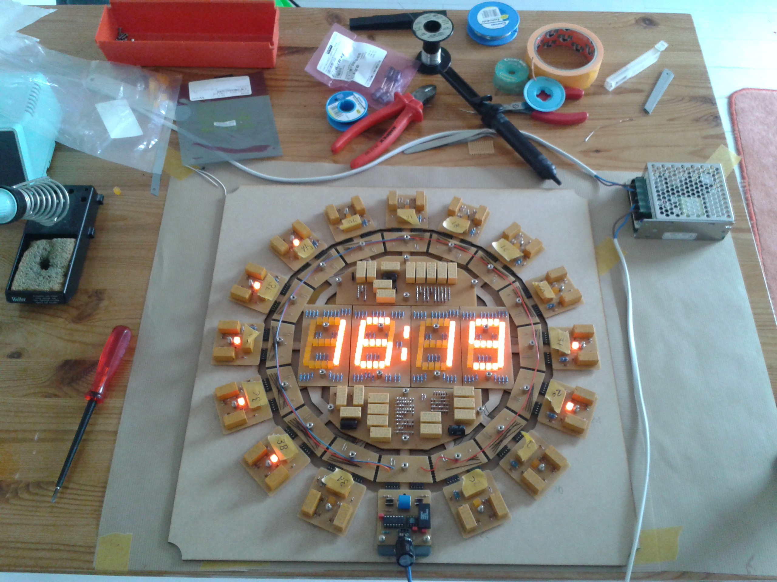
12/14/2022 at 16:09 • 0 commentsYes, finally, the clock is finished. In fact, it has been since the summer of 2020 but I'm just getting around to writing about it. For a long time, the electronics were done, but the clock just sat in a box because I could not decide how I wanted to finish the clock from a mechanical standpoint. All the separate PCBs were screwed to a temporary MDF template that I lasercut back in 2015. I had made a lot of different designs for how to mount all the boards so you could actually hang it on the wall like a real clock, but I was not content with any of the designs. During the pandemic I finally bit the bullet and designed a minimal 3D-printable frame that all components could mount to. This is the final result:
![]()
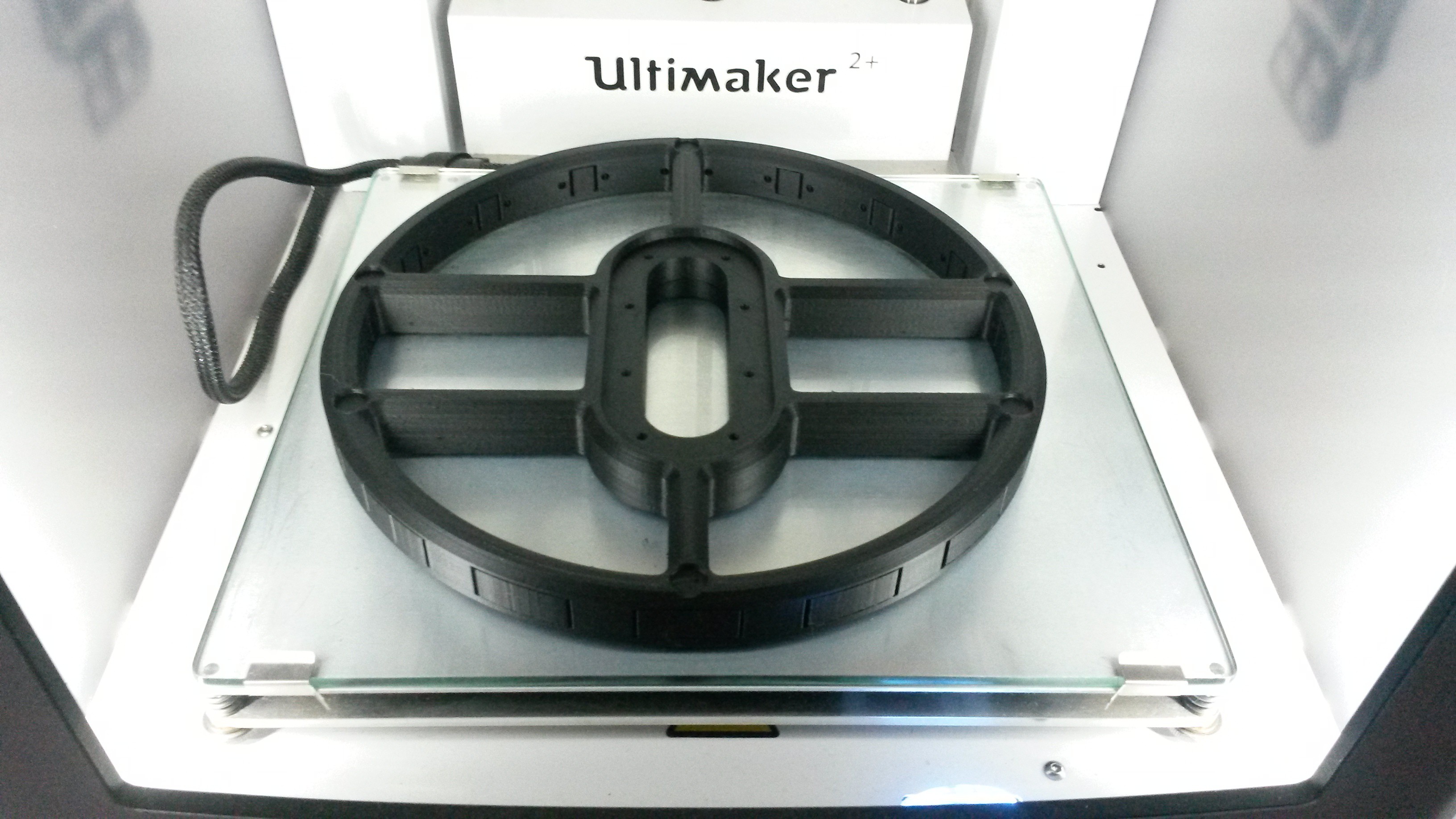
The frame is hardly visible, as it is printed from black PLA. The frame consists of a center section with 16 spokes that slide in an screw to it. The parts have threaded brass inserts where the stainless hardware screws into. The center section was almost too large for my printer, I had to flatten the sides of the circle by a few millimeter. Here it is with the printer just finished:
![]()
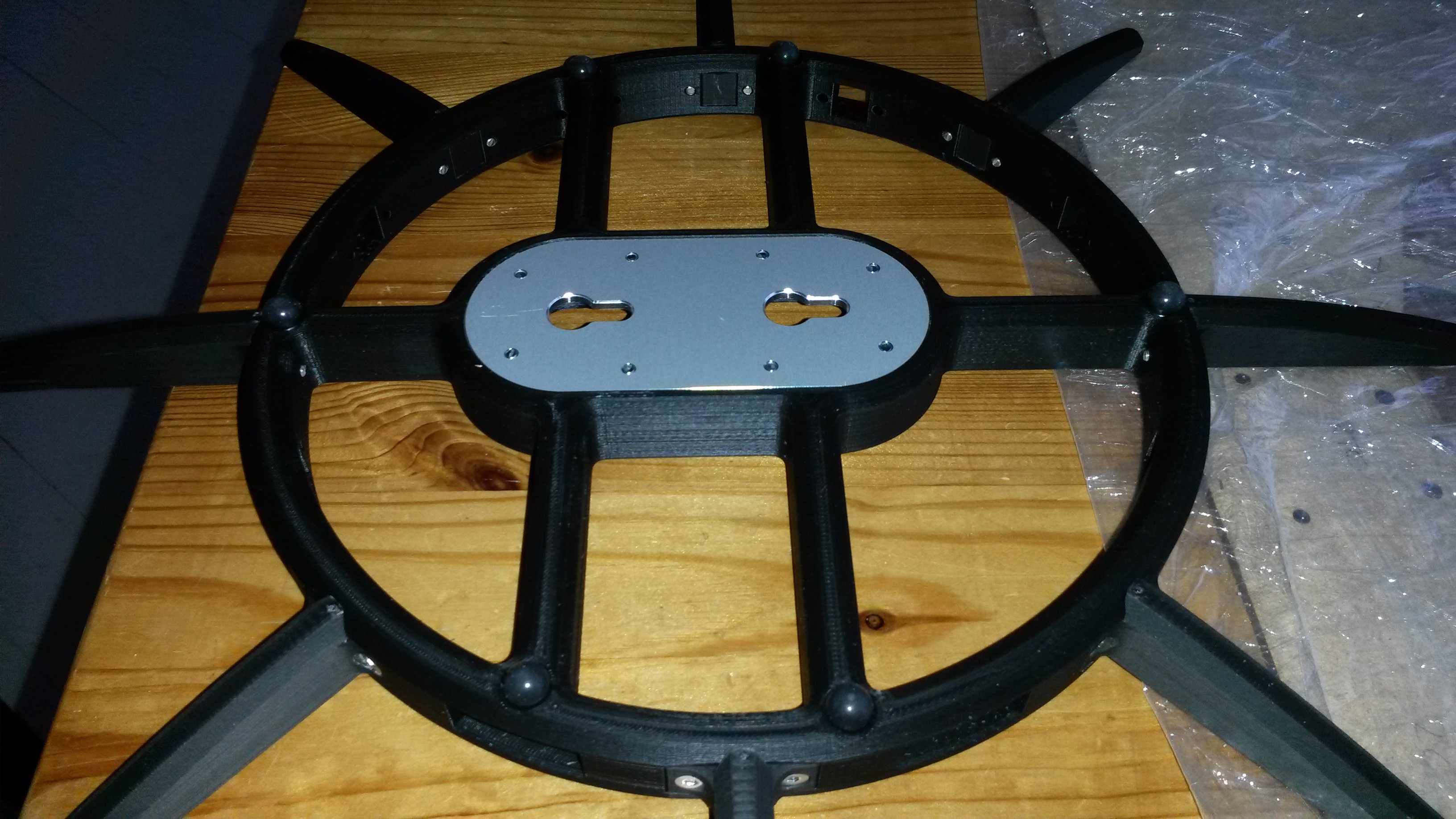
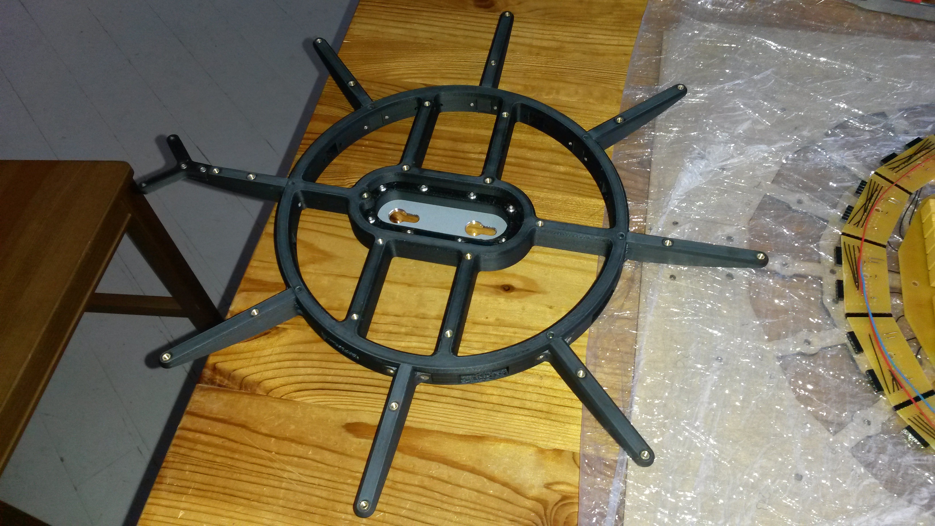
After printing the spokes and mounting them, I designed an aluminium plate that screws in the middle of the center section. This has keyhole slots that are used to mount to the wall. The plate was ordered from Schaeffer AG (Frontpanel Express in USA). Here's the frame with half the spokes fitted, I could not find a picture of the completed frame.
![]()
![]()
You can see the brass inserts on the front and a few rubber feet on the back so it doesn't sit right up on the wall but a little distance from it. I think it looks good. In this last picture you see how it scales on my wall. The red and orange box on top of the cardboard boxes is the power supply. I printed it from leftover filament, that's the reason for the weird colors.
![]()
Let me know what parts of the clock you still want me to describe. The power supply is just a framed switching supply in a custom printed box with a nice yellow fabric lamp cord. I think that the only part missing from the technical description is the working of the carry circuits. This deserves a separate writeup.
-
Foto update (nov 2018)
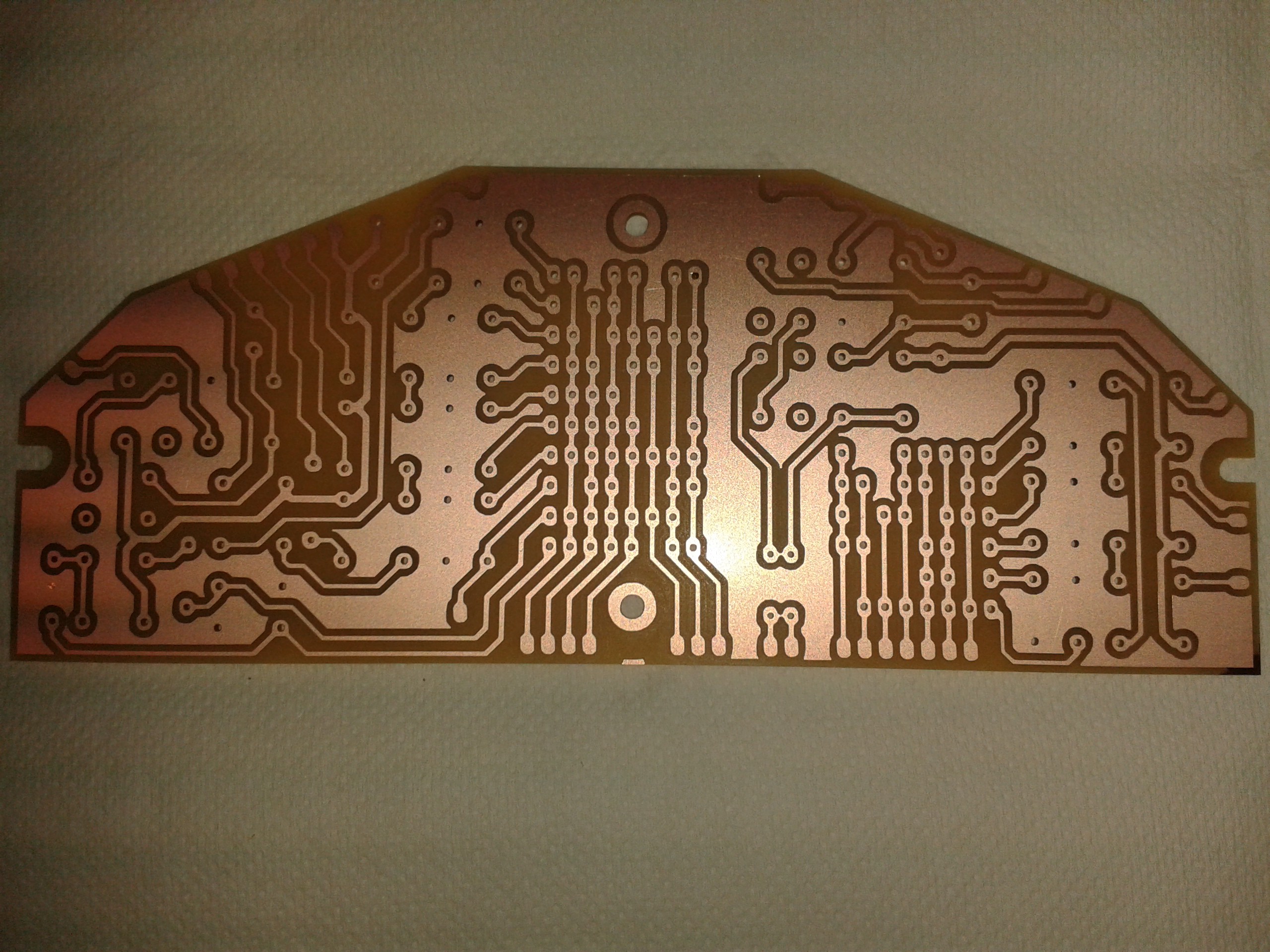
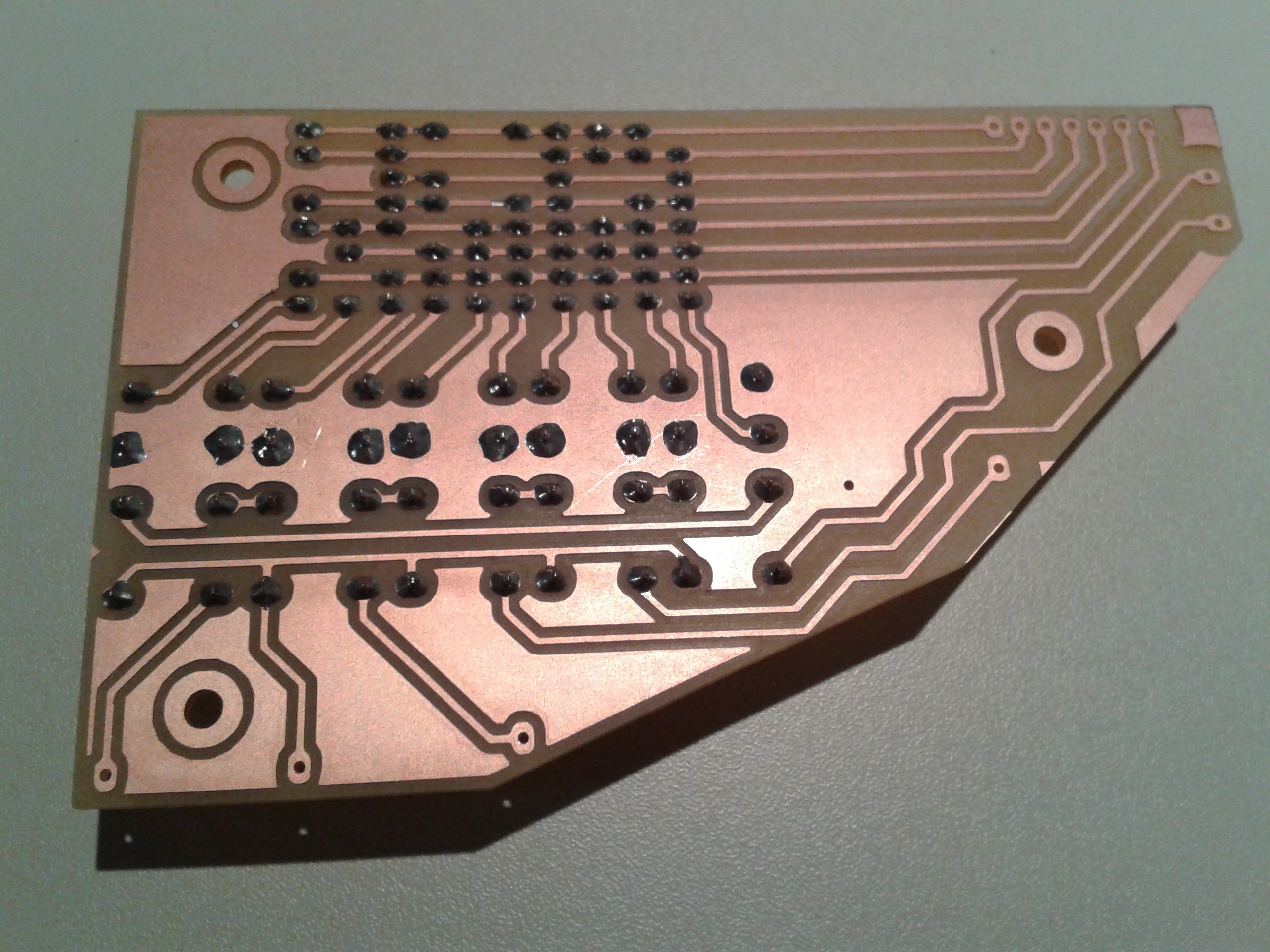
11/19/2018 at 15:58 • 5 commentsThe last PCB, fresh off the mill. This is the lower decoder board. It replaces the two separate decoders I made earlier, because I had to add extra circuitry for the carry logic.
![]()
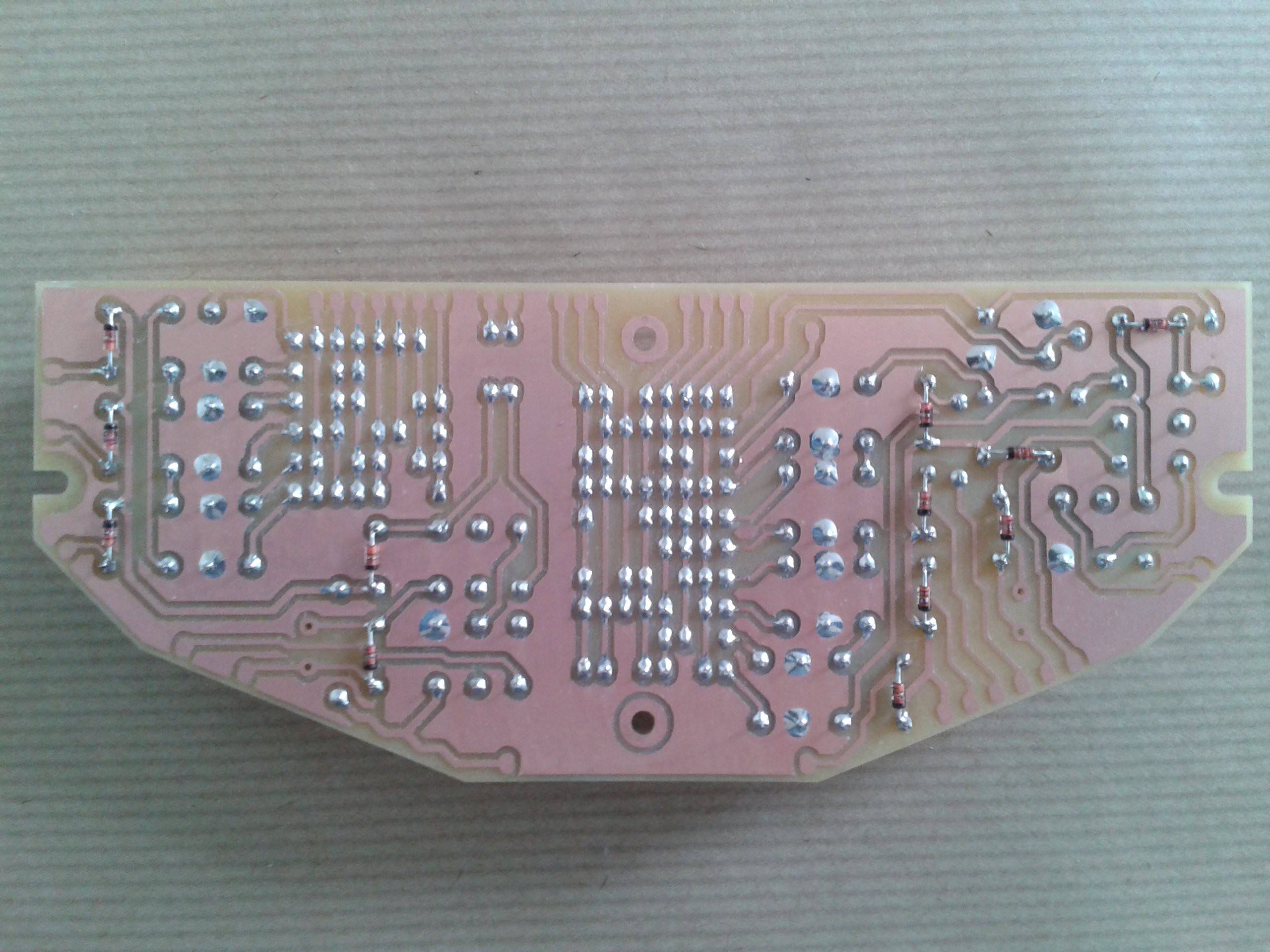
Here it is after soldering.
![]()
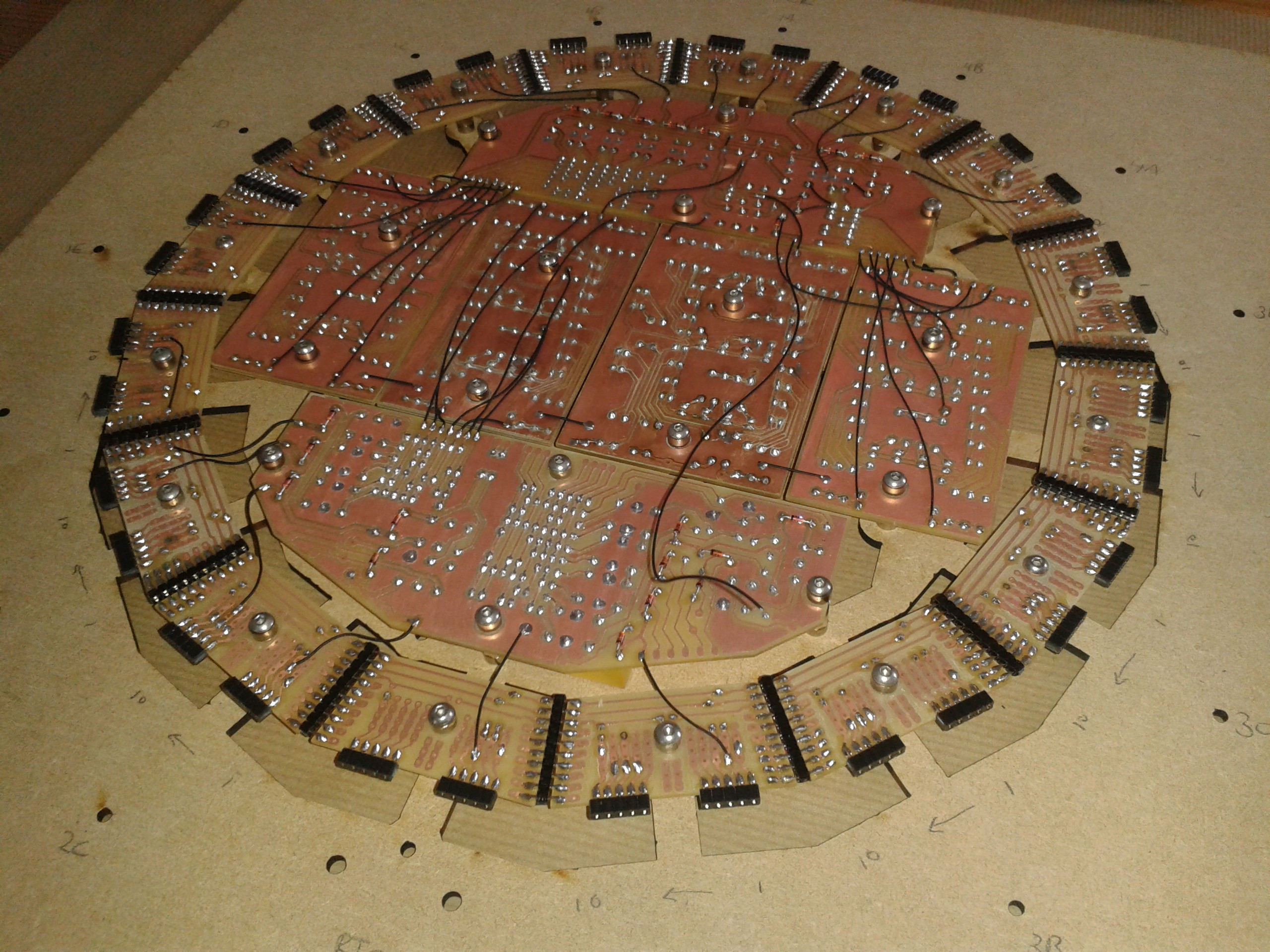
Those diodes are a real challenge to do consistently. Here is a view from the back of the clock. I had to transfer all the PCBs to a new carrier board (the piece of MDF), without disturbing the delicate wiring. I removed the flip-flop boards to make it easier to handle. You can see I just started wiring in the new lower decoder board.
![]()
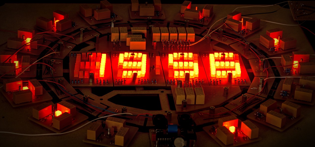
And there it is, in all it's warm glowing glory. Completely functional, although the wiring needs some work. This is a major milestone for me. The first time all the components are in place and everything seems to be working. Now I can start designing the plexiglass frame that it will be mounted in.
![]()
That's it for now. Thanks for reading! Cheers.
-
Timekeeping and RTC
06/20/2018 at 13:00 • 0 commentsCompromise
One part missing from my description so far is the part that does the actual timekeeping. I am a bit reluctant to publish this, as I consider it the least 'pure' part of the design. Every other part of the clock only uses old technology: Relays, diodes and resistors. But this small PCB has a microcontroller, crystal, real time clock IC, two MOSFETs, a lythium battery and a microcontroller. Those are all quite modern components. But every design has compromises and this is where I made most of them.
Timekeeping
I wanted the clock to keep accurate time, otherwise, what good is it? What I needed was one clock pulse per minute to the minutes section. When the minutes rolled over from 59 to 00, that could be detected and a clock pulse to the hours section could be generated.
I considered multiple options to do this. From reading the 50Hz net frequency and dividing it down, to using a synchronous motor to generate a pulse once per minute. In the end I opted for using a real time clock and crystal and a microcontroller to generate the clock pulses. There is no carry circuit from the minutes to the hours. The microcontroller generates a separate clock pulse for the minute and hour circuits.
Schematic
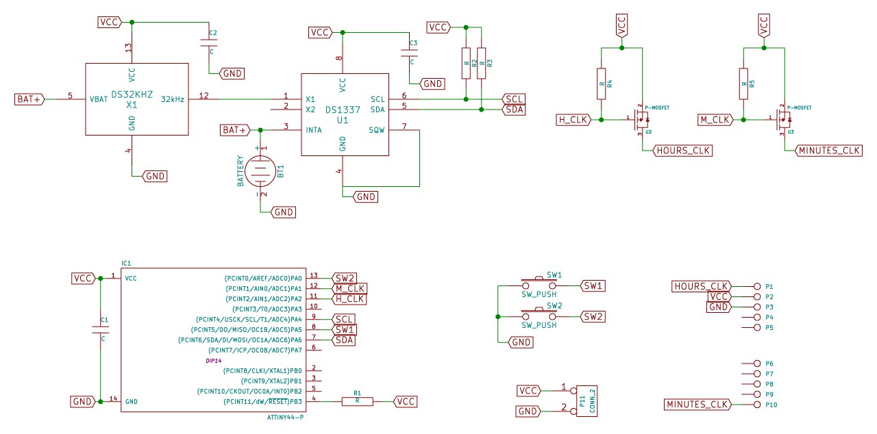
Below you see the schematic of this circuit board. In the top left is the DS1337 real time clock. This does the actual timekeeping. It has a battery to continue operating when the power to the clock is disconnected. To the left is the DS32KHZ crystal. It is a very accurate temperature compensated crystal, that is supposed to be 2PPM accurate. That is just over a minute deviation per year!
![]()
In the bottom left is the Atmel ATTiny44 microcontroller. It read the time from the RTC via the I2C bus. The microcontroller drives two MOSFETs, who supply the clock pulses to the rest of the relay clock circuits. I chose MOSFETS instead of relays to save space and because these relays would wear out quickly.
Functionality
The microcontroller continually reads the time from the RTC. When a minute rollover is detected, it outputs the clock pulse to the minute and/or hour circuits. The two pushbuttons are used to set the time. One for the hours and one for the minutes. Whenever a button is pushed, the minute or hour is incremented and the seconds are zeroed. This allows for accurate timesetting.
One last gimmick I implemented is a showy power up sequence. The relay counter circuits start at 00:00 when the power is connected. The microcontroller starts with incrementing the minutes first and then the hours. It's just a nice little element to show off the mechanism to someone.
![]()
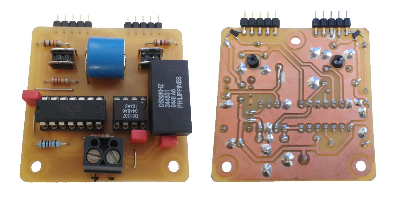
Above you see the finished circuit board. The soldering on the MOSFETs is a bit dodgy and I may redesign it later to use a different RTC. The Maxim DS3231 looks like a nice candidate. It's just as accurate, but has an integrated crystal. For now I am happy with this though.
-
Update June 2018
06/20/2018 at 11:11 • 1 commentIt's been a long time since my last update. Although unfinished, the project is still alive. I got sidetracked with a different project, work and moving house two times. In the background I'm still working on this one. It is one of my dearest designs and I fully indend to finish it.
![]()
At this point, three things need to be done to finish this project.
- The lower decoder PCB. This holds the single hours and tens minutes decoders as well as the minute and hour carry circuits. I had a lot of trouble with fitting all the components on the limited board space. But I finally finished the board layout a few months ago. I only need to mill out the board and solder the components.
- The power supply. I have all the parts I need. Just need to finish the enclosure and order some nice wiring to connect it to the clock. I'm thinking of using 'fabric wire' (or lamp cord) with the nice colored insulation. This will give it a vintage look.
- Mechanical backplane. Right now I am using a piece of lasercut MDF sheet to hold all the parts. I have been thinking about how I want to mount all the PCB's in the end. Right now I have decided to use a 6mm acrylic sheet. I am almost finished with the design. Next I need to find a company who can mill and tap it for me as I don't have access to the tools I need to do it myself.
-
Decoders continued...
05/18/2016 at 10:03 • 5 commentsThe last time I wrote about the decoders I was short on explanations. I had just built the first one of four. Now several months and a lot of redesigns later I am ready to give a longer explanation.
Originally I intended to build four separate decoders, each one driving a single seven segment display. However I was running out of space so I had to combine the decoders together in order to fit some extra relays responsible for carry and reset of the flipflop's.
Functionally there are the following separate circuits:
- Single-minutes decoder, connected to flipflop's 1A - 1E
- Tens-minutes decoder, connected to flipflop's 2A - 2C
- Single-hours decoder, connected to flipflops's 3A - 3E
- Tens-hours decoder, connected to flipflop's 4A - 4B
- Carry single-minutes to tens-minutes
- Carry single-hours to tens-hours
- Reset hours when '24' hours state reached
These circuits are now combined into two decoder boards:
Upper decoder:
- Single-minutes
- Tens-hours
- Reset hours
Lower decoder:
- Tens-minutes
- Single-hours
- Carry minutes
- Carry hours
Because I was running out of space, I had to move the functional blocks around a bit so that in the end each decoder board contains exactly ten relays.
Decoding the digits
The table below shows the decoding of the four displays.
DECODING LOGIC
! is NOT
& is AND
i.e. !A & E is (NOT A) AND E


Single-minutes

1A  1B  1C  1D  1E  |  Num  Logic
--------------------+--------------
0   0   0   0   0   |  0    !A & !E
1   0   0   0   0   |  1    A & !B
1   1   0   0   0   |  2    B & !C
1   1   1   0   0   |  3    C & !D
1   1   1   1   0   |  4    D & !E
1   1   1   1   1   |  5    A & E
0   1   1   1   1   |  6    !A & B
0   0   1   1   1   |  7    !B & C
0   0   0   1   1   |  8    !C & D
0   0   0   0   1   |  9    !D & E


Tens-minutes

2A  2B  2C  |  Num  Logic------------+--------------
0   0   0   |  0    !A & !C
1   0   0   |  1    A & !B
1   1   0   |  2    B & !C
1   1   1   |  3    A & C
0   1   1   |  4    !A & B
0   0   1   |  5    !B & C


Single-hours

3A  3B  3C  3D  3E  |  Num  Logic
--------------------+--------------
0   0   0   0   0   |  0    !A & !E
1   0   0   0   0   |  1    A & !B
1   1   0   0   0   |  2    B & !C
1   1   1   0   0   |  3    C & !D
1   1   1   1   0   |  4    D & !E
1   1   1   1   1   |  5    A & E
0   1   1   1   1   |  6    !A & B
0   0   1   1   1   |  7    !B & C
0   0   0   1   1   |  8    !C & D
0   0   0   0   1   |  9    !D & E


Tens-hours

4A  4B  |  Num  Logic
--------+---------------
0   0   |  0    !A & !B
1   0   |  1    A & !B
1   1   |  2    A & B
0   1   |  X    -
Let's have a look at the first table, which shows the decoding of the rightmost digit, the single-minute digit. This digit is controlled by the first five flipflop's, numbered 1A through 1E. The first five colums represent the output state of these flipflop's. Notice the progression typical of a johnson counter, totally different from a binary counter. Next you see the number that this state represents and the final column shows what logic is needed to decode a number. For example, to decode the number '5' , flipflop A and flipflop E have to be both on.
Implementing the logic
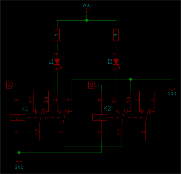
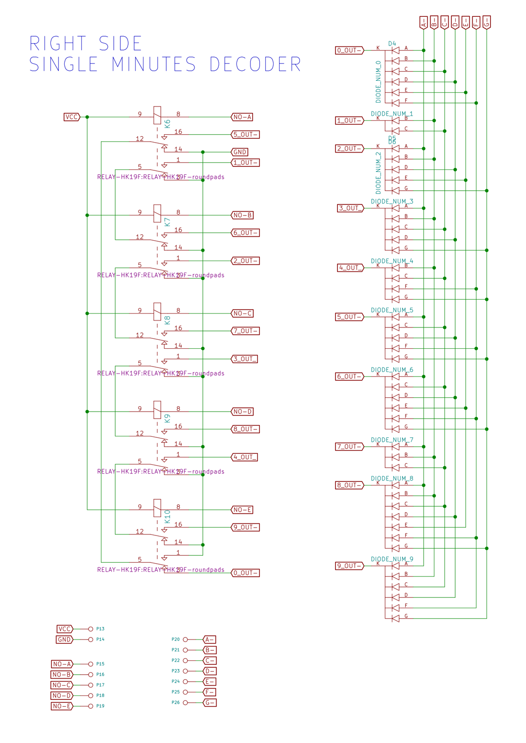
The logic to decode the state of the flipflop's is all implemented, again, in relays. As you can see, every 'statement' consists of two inputs that are logically AND-ed together. To get an AND function in relays, you simply chain the outputs of two relays together. So to get A & B, you chain the normally open outputs of two relays in series. The current flows through the contacts only when both relay A and relay B are on. By using a combination of the normally open and the normally closed contacts you can implement the NOT function as well.
A very convenient property is that the combinations form pairs that are opposites of each other. For instance A & !B and !A & B are opposites. So are B & !C and !B & C. In fact, the ten combinations form five pairs. This property allows you to save relays. To implement the logic for a pair, only two relay contacts are needed, one from each relay. Because the displays are made of LED's, current can only flow through them in one direction. I am making use of this by wiring the LED's together in the opposite direction. See the little schematic below.
![]()
Two relays, K1 and K2 with their inputs A and B. The outputs are LED's D1 and D2. The outputs of the relays are wired in series to produce the AND function. if both relays are off (!A & !B) the grounds are wired together and nothing happens. If both relays are on (A & B) the LED's are wired together in the wrong direction, no current can flow and thus nothing happens. Only if one of the two relays is on, and the other is off can the current flow to ground through one of the diodes. The behaviour of D1 can therefore be expressed as A & !B and the behaviour of D2 as !A & B.
This example shows just two states to decode, but decoding the other states works the same way. Each relay has two sets of contacts. For decoding one pair, only one set of contacts is used. Each relay is involved in the decoding of two pairs. The second set of contacts is used for decoding the other pair.
Look at the relay connected to the output of flipflop 1A. This relay is involved in the decoding of four pairs: !A & !E, A & !B, A & E, !A & B. This is why it's possible to decode ten numbers with just five relays. Below is the full schematic of the upper decoder.
![]()
![]()
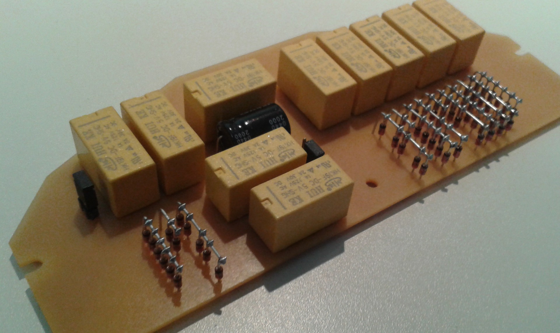
And here's the final PCB of the upper decoder after milling and soldering
![]()
![]()
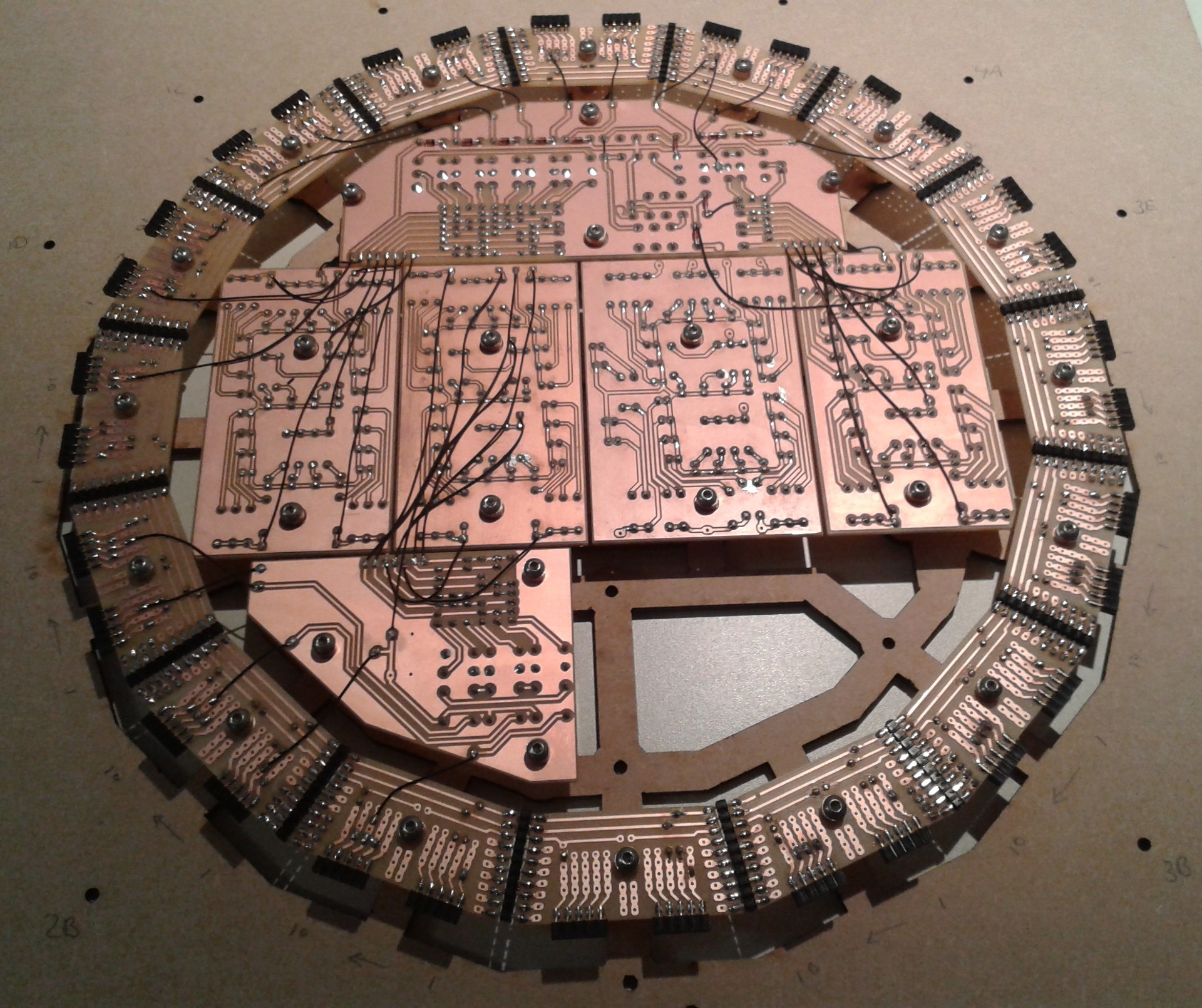
And finally here's the back of the clock while wiring the new decoder into place. For this procedure I had to transfer all the boards to a second assembly frame (lasercut from 3mm MDF) so I could flip it over without moving the boards around. The flipflop boards are removed to reduce stress on the boards and reduce weight while working on it.
![]()
-
Stuck... Unstuck ... and redoing some work
05/07/2016 at 09:16 • 1 commentIt has been a while since I last posted a log entry. The reason is that I got stuck. I guess this happens to all of us from time to time. Let me tell you what happened.
When I designed the broad layout of the circuit boards I had the whole thing figured out for 90%. The other 10% I would come up during the process. Or so I thought. I did some initial tests to confirm my understanding of the mechanism and after that I got to work designing and fabricating all the individual boards. I never forgot about my little 'problem', but I was still confident that I would come up with a solution when the time was right. And then all of a sudden I was done doing all the work that could be done before solving my little issue. This is when I got stuck...
So what was the problem? It has to do with carrying the clock signals from the lower to the higher digits and resetting the counters back to zero at the right moment.
I had sort-of solved this issue with the minutes counters. They already roll over to zero after 59 on their own. This is because the lover digit can only count from 0 to 9 and the higher digit can only count from 0 to 5. The only thing I had to do was carry the clock from the lower digit to the higher one when it rolled over to zero. So every time the lover digits rolls over, it sends a clock to the higher one and increments it by one. I should have added an extra relay to buffer the carry signal, but instead I just wired the clock for the higher digits directly to the output of the last relay in the lower digit counters. This worked, but had the disadvantage that on power-up the digits would reset to "1-0" because the higher digit would get clocked immediately form the lower "0" digit. I could live with that, for now at least.
The hours counter is a little different and this trick wouldn't work. The really big problem was that I had to reset it at the right moment. These counters don't automatically roll over from 23 to zero just on their own. I had to force it somehow. Only I had no idea how to do it. This is why I stopped working on the project for several months. There were too many conflicting issues to solve all at once. I had to figure out how to do it electronically. But this surely meant extra relays and I didn't have board space for extra relays. And I did not want to compromise the look of the clock. So I was stuck. Stuck with this thought in my mind that I couldn't solve it.
But in the end I did solve it. As always, at some random time the solution came to me. And this is what it was.
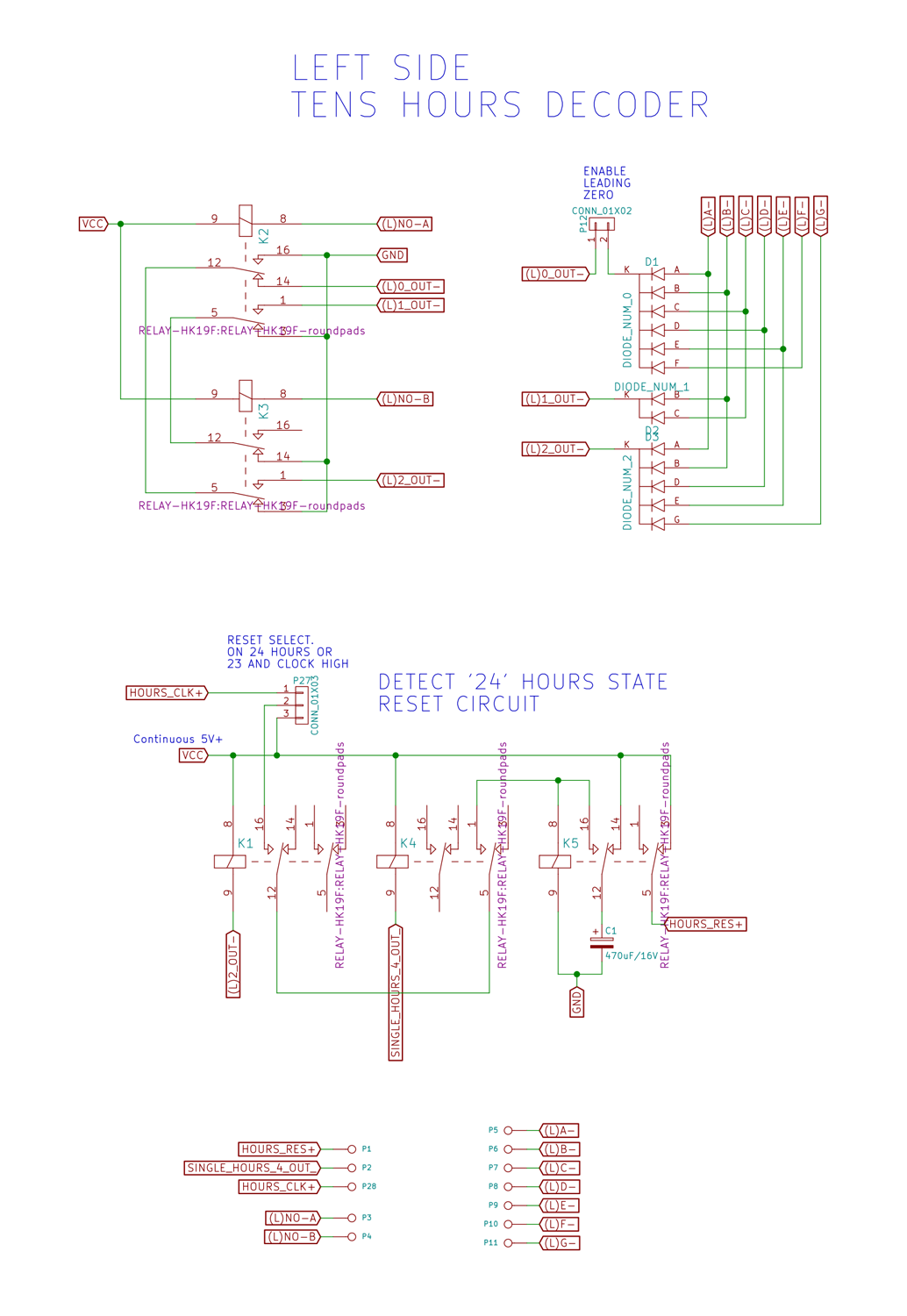
I decided that I had to detect the "2-3" state and then on the next clock reset the higher and lower hours counters back to zero. The flip-flops are reset by cutting power to them, that's the only way. So the power to these flip-flops now runs through an extra relay that can be triggered to reset the hours counters. I use the outputs of the decoders that run the display to detect the "2-3" state. Both the 3 of the lower digit and the 2 of the higher digit run to separate relays. These are chained to form a logical AND operation. Then when the next clock pulse comes in, these two relays trigger the reset relay. I added a big capacitor, to keep the reset relay energised long enough to make sure all flip-flops are reset.
With the reset covered, a new problem arose. Because the hours counters had to display "0-0" on reset, I could not use the same trick as with the minutes counters to carry the clock from the lower to the higher digit. So I had to include a buffer relay. Together with the reset relays this was an extra 4 relays and I had no board space left to place them. This was a real problem as the layout of all the circuit boards could not be changed any more.
The only thing I could do was redesign the decoder boards. Originally I had designed them as 4 separate boards, because of restrictions on the size of circuit boards I could mill at the Fablab. Unfortunately, with all the mounting holes for the extra circuit boards I lost a lot of space, space that I desperately needed for the extra relays.
I decided that a redesign of the decoders was in order. I recombined the 4 separate decoders into 2 decoder boards. A upper decoder that decodes the single minutes and the tens hours and a lower decoder that decodes the tens minutes and the single hours. I counted the total number of relays, and tried to divide them evenly among the two decoder boards. This meant a few extra wires running between them but that's acceptable. The last few days I have finished the layout of the upper decoder and milled the circuit board at the lab. I will post pictures when I'm done soldering.
So why the long write-up? I wanted to explain some of the deeper design problems that I faced during this very long process. In the hope that you learn something from it and that it may help you in your own projects. When I finally cracked the problem I was very relieved that I could continue the build. I asked myself if I could have avoided this by designing the entire clock for 100% before starting the build. The answer is no. At the beginning I did not have the understanding that I have now. By working on it, building it and debugging it I gained a deeper knowledge of how the circuits work. I needed this deeper knowledge to design these last, but very important, missing details. I took a risk by starting the build without a complete finished design, but I had confidence in my abilities to solve the problems that came up later. This eventually paid off. Without taking this risk, I would not have started the build at all because at the time I did not have a complete picture of the finished result.
So start building your project, even when you don't have a complete picture of the end result. The experience gained in the process will improve your design more than thinking out every little detail beforehand.
-
2nd digit and RTC
01/11/2016 at 12:50 • 0 commentsToday I finished the decoder for the 2nd digit. The minute display section is now complete. As you can see in the video, I finished a prototype of the battery powered real time clock as well. When the power is applied, the clock shows "10" minutes, this is because the 2nd display is clocked by the first display when it shows 0. So on power up the 2nd display immediately gets a clock and increments.
Connected to the relay clock you see an Arduino with a real time clock. I use a Maxim DS1307 to keep the time. It is connected via I2C to the processor. I have a temperature compensated crystal oscillator, a Maxim DS32KHZ, which is supposed to be accurate to +/- 2 PPM per year. This is only a prototype, in the end I will design a small rectangular board that will go in the free position at bottom of the outer circle.
After the processor powers up, it reads the time in the RTC and then sends out clock pulses tot the relays until the time on the displays corresponds to the time in the RTC. The two buttons can be used to increment the hours or the minutes. On incrementing the minutes, the seconds in the RTC are reset to zero as well.
The clock is now half done! On to the hour section. This will require some more relay trickery to get the thing to roll over from 23 to 00. I have yet to design the decoders for this, so I hope it will all fit on the available board space.
-
It's Alive!
01/05/2016 at 10:50 • 2 commentsThis weekend I managed to complete the single-minutes stage of the clock. After testing the flip-flop's and building the decoder I could finally connect everything together. The completed seven segment display has been sitting on my bench for months, waiting to be used. I now have one working digit. This is a milestone for me, the first time I have everything working from the counting logic to the display. As you can see in the video, the clock signal is generated externally by an Arduino. For now anyway. Enjoy the soothing clicking of the relays.
-
The Decoders
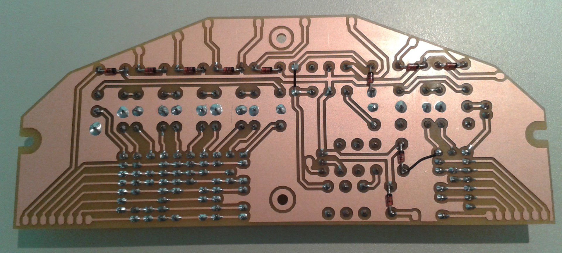
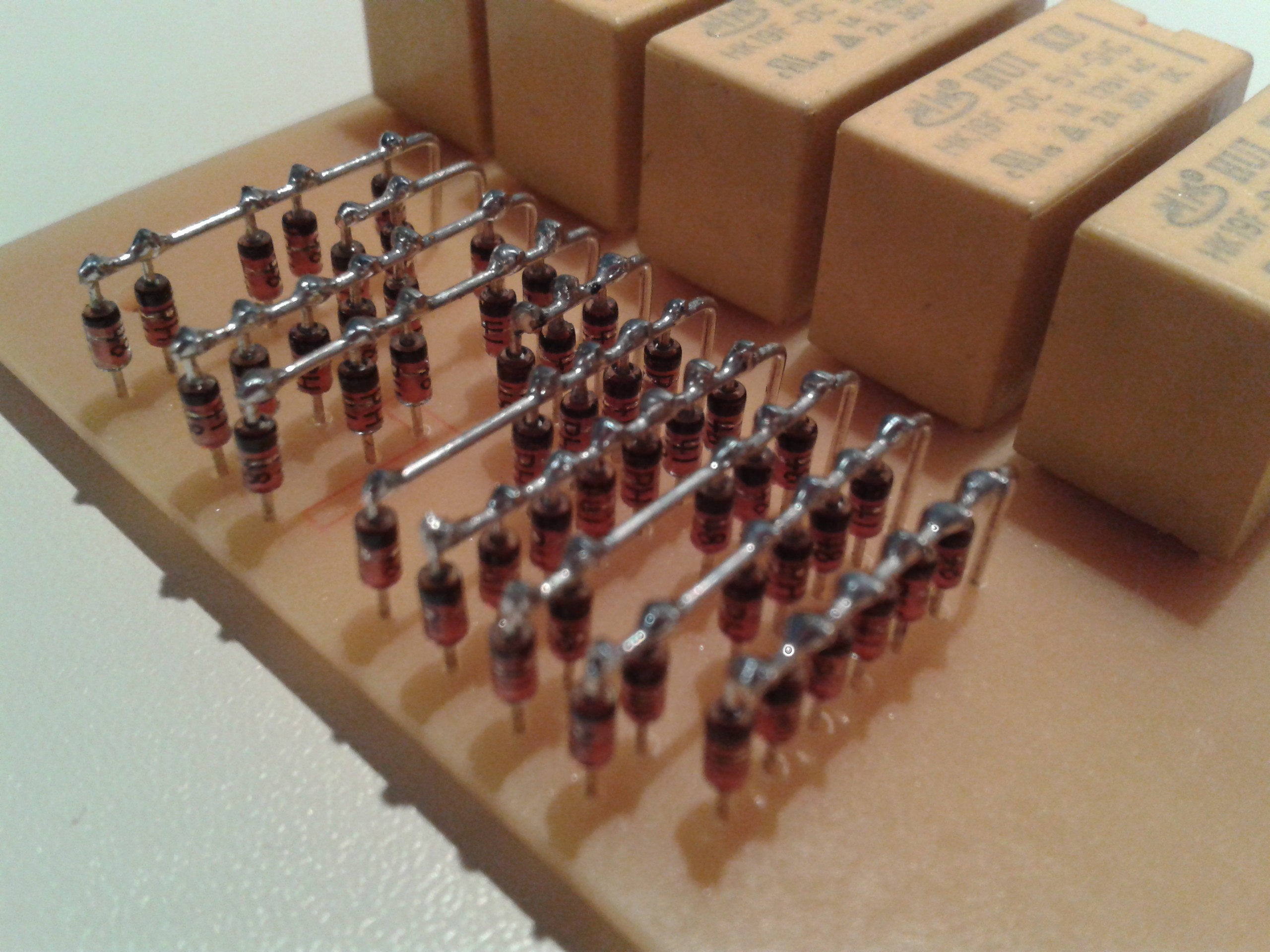
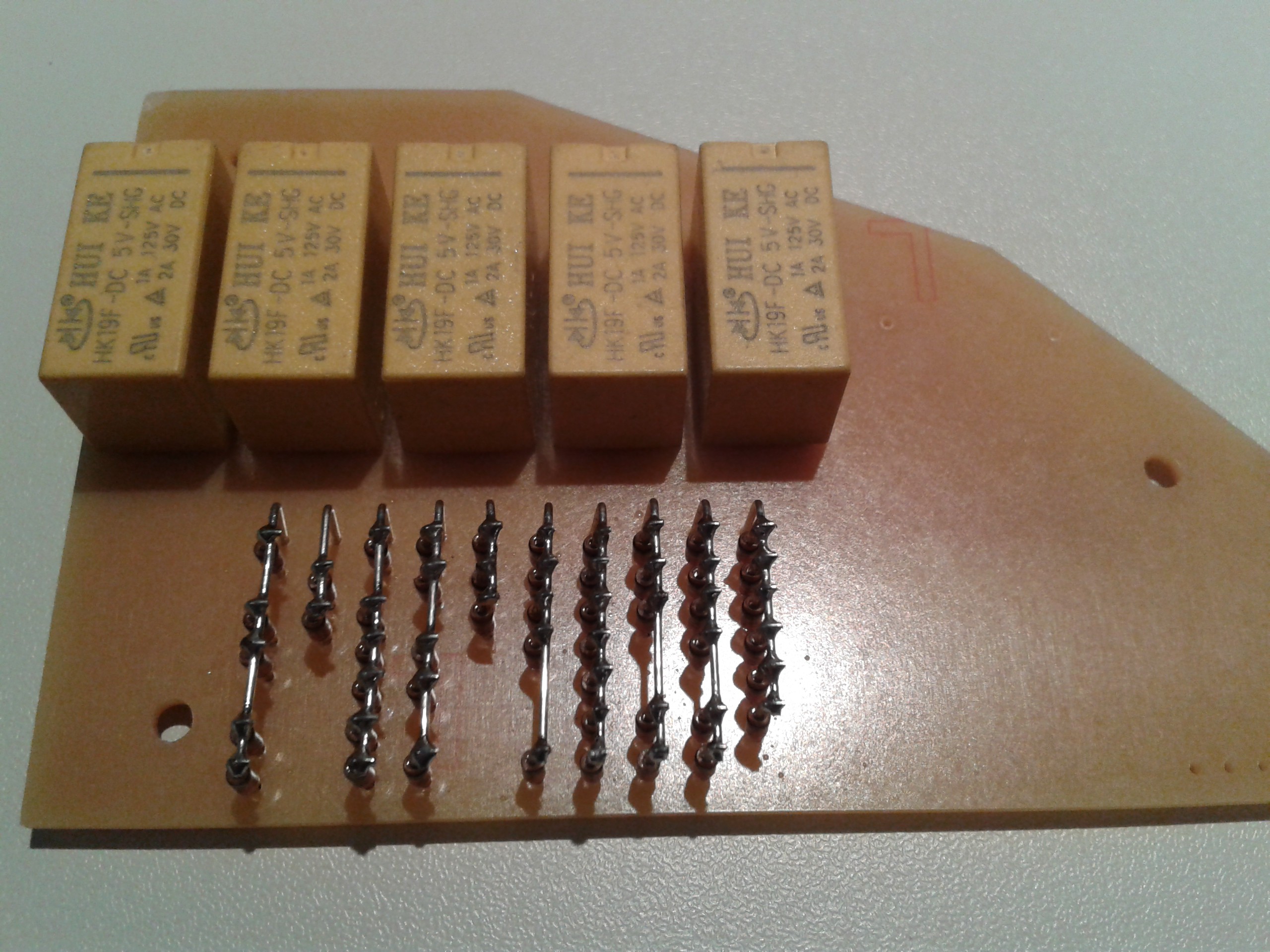
12/30/2015 at 14:10 • 5 commentsToday my latest shipment of relays got in from Hong Kong, so I can finally finish one of the decoders. I am just posting some pictures for now, but I promise to add a complete description later. The decoder shown here is the first of four. It is the single-minutes decoder. It has five inputs, from the first five flip-flops and it drives one single seven-segment display. At the bottom you see the array of diodes that decode the ten different digits. The five relays at the top are responsible for the AND operations to detect the correct state of the flip-flops.
![]()
![]()
![]()
Relay Logic Clock
A digital 24 hour clock using only relays and diodes for the counting logic.
 Dave Gönner