-
New batch delivered !
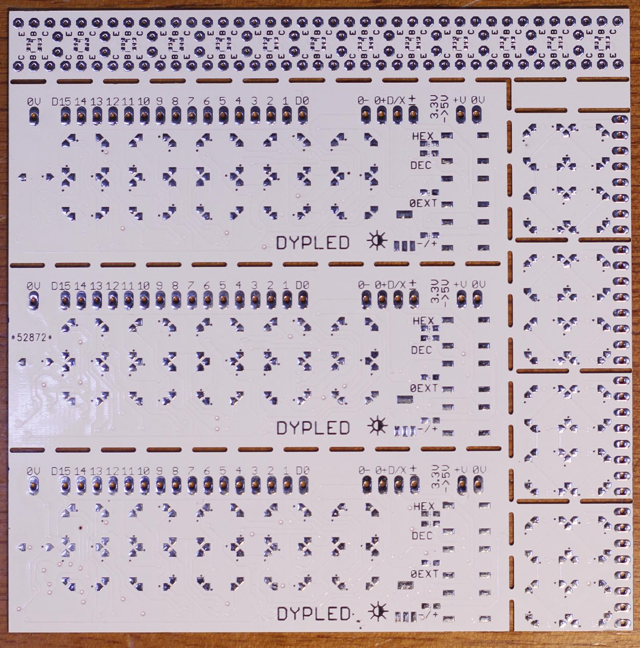
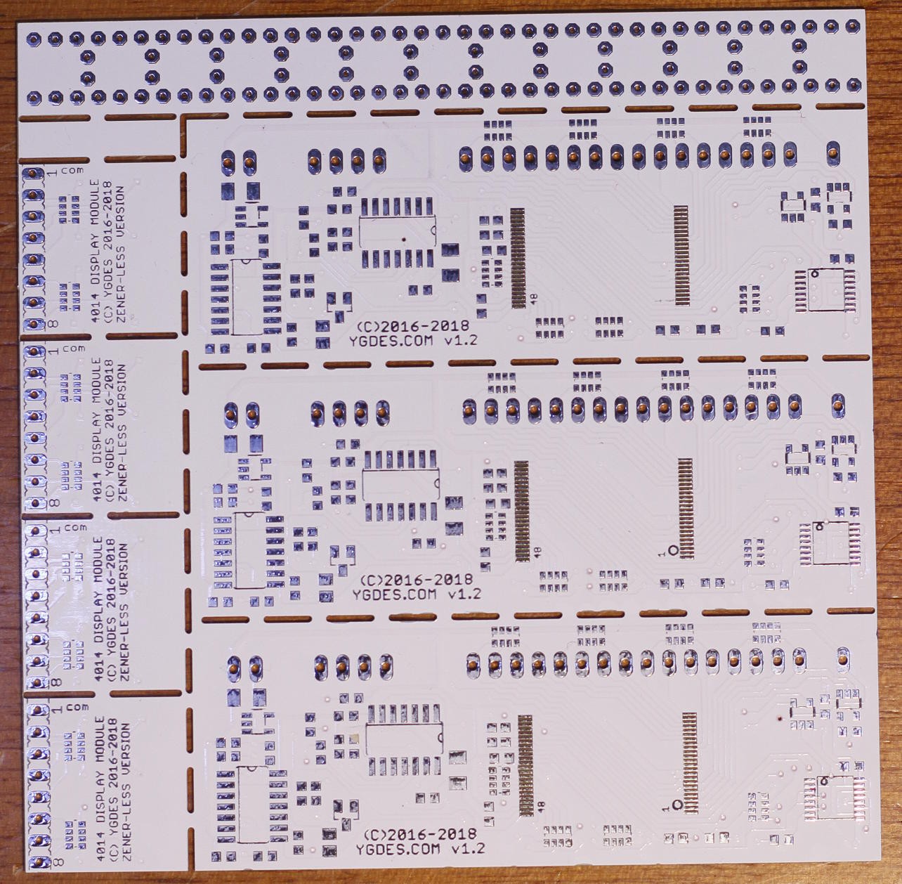
07/30/2018 at 22:50 • 0 commentsThe PCB have finally arrived in the workshop :-)
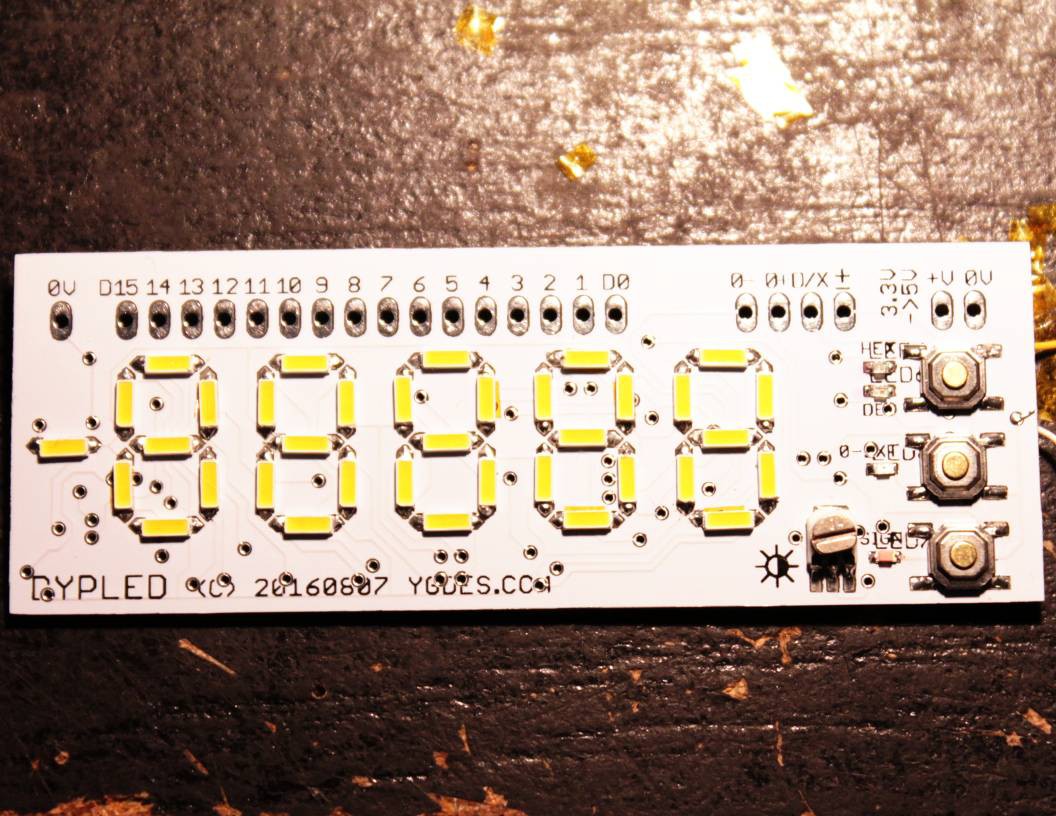
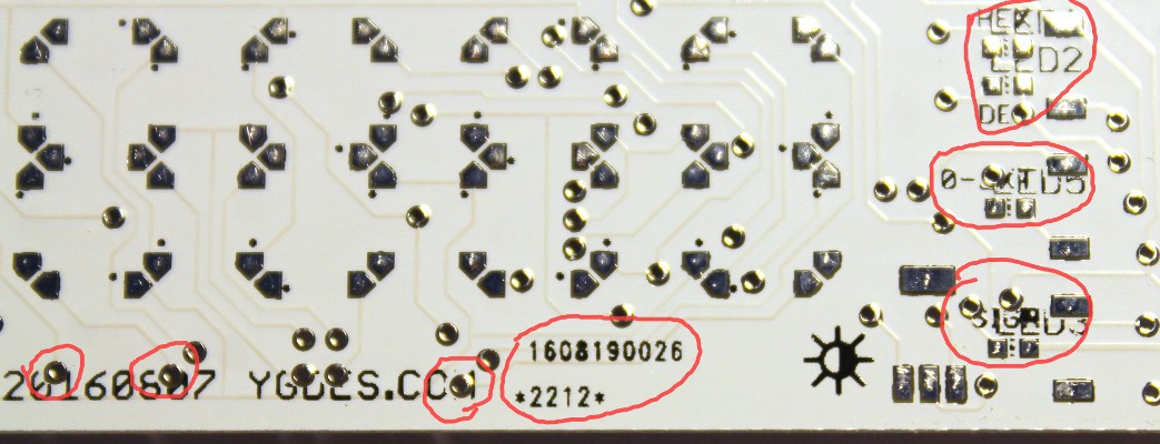
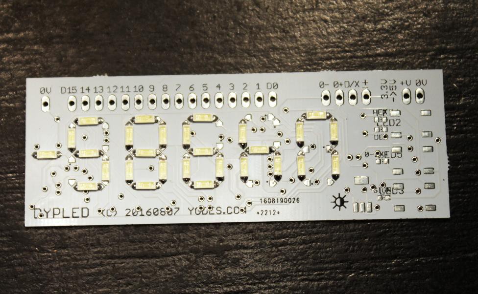
Tented vias are great :-D No more tricky isolation !
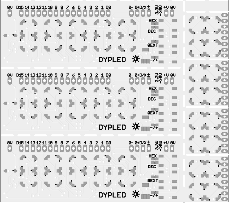
This time I delivered GERBERs instead of EAGLE files and I triple-checked everything. The preview on the website is much better than for the first batch. Once again, DirtyPCB's subcontractor couldn't keep from adding their serial number in an awkward place, despite having left a blank area where it could fit. Next time I'll have to reverse all the layers so the marking doesn't appear on the front/top side...
This time the PCB is thicker : 0.8mm, less fragile and easier to handle on a breadboard.
The remaining space is used by some #4014 LED minimodule as well as some proto strips for the BFS480 in SC70-6 used by #YGREC-ECL.
-
New batch
06/16/2018 at 15:05 • 0 commentsThanks to the seed funds from the Hackaday Prize, I've submitted an order for another batch of DYPLED PCBs (and also some #4014 LED minimodules).
![]()
It was long overdue but thanks to the logs, I have recovered the critical information and solved the previous problems. This time, no problem with tented vias because I generated a set of GERBER files that I carefully examined.
I have also solved the decoupling issue and made several minor cosmetic tweaks.
See you here in a few weeks...
-
Another spinoff
06/13/2017 at 10:36 • 0 comments@bobricius has used the 4014 system for his #BPW34 solar powered led watch and the project has been covered by Hackaday.com and Adafruit
Congratulations ! I feel vindicated when others benefit from my ideas :-)
-
PCB rev.2
04/24/2017 at 12:16 • 0 commentsA new version should appear. Not only must it solve the tented vias problem and the decoupling problem, but also gain a bit of room for the added capacitors.
There is one area with little usage near the brightness potentiometer. But it's far from the 3.2V rail. Another solution is to switch the 74HC04 package from SOIC to SSOP. I got some TC74VHC04FS but they are rated at 5V, I'll have to see how they behave when undervolted at 3.2V...
OK, don't buy a part before looking at a datasheet, kids !
In my case, I was lucky and it says :
- High noise immunity: V NIH = V NIL = 28% V CC (min)
- Wide operating voltage range: V CC (opr) = 2 V to 5.5 V
I shoud probably add a bit of hysteresis...
-
Decoupling
02/10/2017 at 18:23 • 4 commentsFranck just spotted a pretty fumble : I have overlooked the bulk capacitors before and after the LP2981.
I think I assumed that the voltage stability was not critical but usually I am very generous with capacitors.
The other problem is : is there any room left ?
-
Resuming
11/17/2016 at 15:30 • 0 commentsThe development of DYPLED had stalled for several reasons. Some were described here, such as the naked vias. There was work, too. And a big problem: the type of LED.
The naked vias are just a matter of ordering yet another batch of PCB with the right GERBER.
Work is done now (#PixelAvenue will open next week)
The LEDs though are a different story. I needed to decide which type of LED I will commit to, from now on. With or without the integrated Zener ?
- With Zener : the routing is much easier but must be re-done from scratch and luminosity is not as good.
- Without Zener : No need to touch the tracks (less work) and everything works as expected, though routing could (and should) be optimised (next time).
The choice does not depend on me though.
The only way to decide was to see what type of LED I could use from now on. So I bought more of these : https://www.aliexpress.com/item/3000pcs-lot-0-2W-SMD-4014-LED-Lamp-Bead13-26lm-White-Warm-white-SMD-LED-2800K/32353970900.html (note: I ordered "warm white", the Zener are in the earlier "cold white" order).
They have been delivered and I just tested them : there is no reverse diode (just like the previous order). This means that the PCB requires no change and I can move forward, with enough stock to ... whatever :-D
-
First prototype
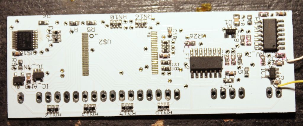
09/06/2016 at 10:19 • 4 commentsToday I decided that the first PCB was good enough to try to solder it. I know I have to order new PCBs but I want to be sure that I removed all the blunders...
I started from the power supply, populated the analog parts then the ICs. This allowed me to locate a short between two pins of the '157 which drew about 50mA...
Without the digital parts of the left, the circuit draws less than 200µA. This increases to almost 2mA with the status LEDs on. In particular the green LED draws about 1.2mA and is not very bright, I must change it... I suppose a recent µC could draw less than the discrete gates but at least it's reasonable and quite convenient :-)
The oscillator (100K and 2.2nF) runs at about 4900Hz and the 74HC74 brings it down to 2450Hz : no flicker is expected.
The circuit still works rather well under the 3V level. Some parameters change (frequency, brightness) but not significantly.
I also tested the front panel interface:
The LED's footrints are too tiny... I added some more soldering surface on the new version (booooh ugly, I should have modified the footprint instead... I'm lazy)
The push-buttons are not insulated and there are interference by mere touching. But it works.
The PWM adjustment works well, according to the ocilloscope :-)
The LED's brightness is important. I've put 10K series resistors to reduce the emitted light but the green is under-efficient, I'll swap it with a true green or white LED...
I also soldered all the parts of the user-facing side and the result is great (I'vewalready covered the problems in the previous log).
Since the Flash chip is not yet soldered, I can individually test the LEDs.
I changed the green LED with warm white. The luminosity is still too high with 10K in series. Trying with 30K.
Note 1: Apparently, it's better to use blue-based LEDs (white, pink) rather than older generations, for better efficiency.
Note 2: 0-extension is controlled by the 74HC74 and resets to set. OTOH the 74HC04 seems to keep the last value across short power outages. Good to know... Ideally, 0-ext should be off, right ? I'm going to update the schematics...
As expected, the board is crazy thin : 3.5mm from the top of the adjustable resistor, to the top of the SOP16 parts.
I don't know how to reduce the height of the resistor, thinner versions will be very hard to handle easily. It's not critical at this point.
The buttons are ultra-thin as well. They are not electrically insulated. Thicker versions (with some plastic enclosure) would solve this problem.
-
Not a failure but not a success either
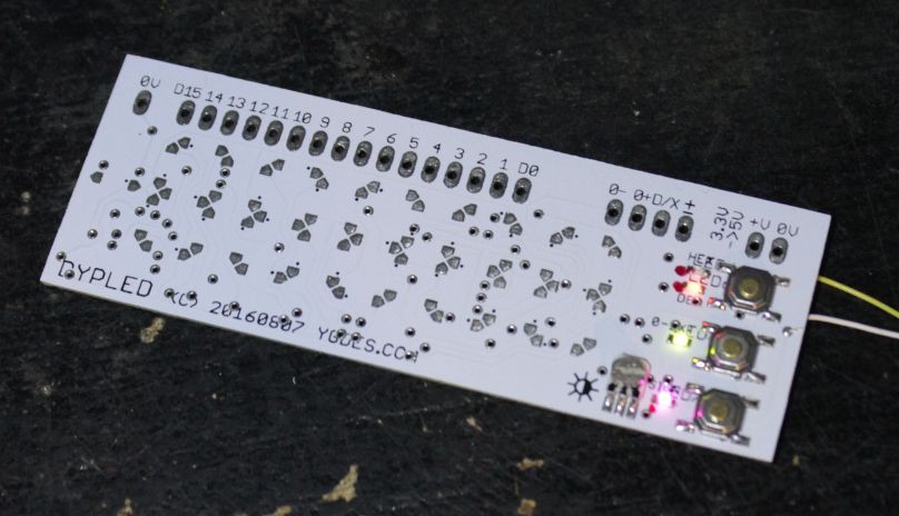
08/28/2016 at 05:30 • 2 commentsI received the latest PCB batch with the first DYPLED boards, and the issues are explained in this page.
I don't think I can make the modules work completely as expected, mainly because of the unmasked vias that will create shorts with the thermal pads of the 4014 LEDS.
At least I can validate other aspects of the module, such as the push-buttons, the PWM, solderability, etc.
20160902: I tried to solder the first LED (when there is no via under them) and the result is pretty good, soldering is not hard (not easy but I didn't experience any difficulty). At least I don't have to change the footprints :-)
Time to test the other circuits !
-
File generation in C
08/20/2016 at 20:59 • 0 commentsIt took me 3h only (and I was not rushing) to translate the JS code into C and get a decent binary file. I've just uploaded the source and the generated file in the main page.
C has its own gotchas but the many debug features I used in JS have been very useful in C so the port was a breeze. Compilation is easy:
gcc -Wall -o shuffle shuffle.cExecution is pretty fast too:$ /usr/bin/time ./shuffle > DYPLED.bin 0.85user 0.01system 0:00.88elapsed 99%CPU (0avgtext+0avgdata 1392maxresident)k 0inputs+4096outputs (0major+111minor)pagefaults 0swapsAnd to check the output, add any argument on the command line.
The source code is very flexible, allowing me to adjust and adapt the data, for any change during the first tests and for the next generation of displays derived from it. -
Number conversion
08/19/2016 at 02:06 • 0 commentsThe last log (Bit shuffling: what goes where ?) explains how the address bits are shuffled. Once the logical value and all the modes/options are obtained, these informations are compiled to generate a 32-bits word that is output to the file, which will program the Flash.
There are two conversion functions : hexadecimal and decimal. They are very similar and in fact can be merged into one, since the base parameter can work very well with this system (I just realise that in ASCII systems, it's better to have separate conversion routines, but here it's pointless). So let's just forget about function pointers...
Given the base parameter, it's easy to decompose the number into digits. There is only one corner case to deal with : what to display when the input is zero. Of course it should display ___0 (and not a void screen, or else people wonder if the circuit works at all) but there are 2 ways to achieve this :
- initialise the display to ___0 and use a while(>0){} loop (which is not entered in the only case where it is zeo)
- or initialise to nothing (____) and use a do..while (repeat...until) so the remainder of zero is written at least once.
The 2nd choice is better because the init value is all-cleared and the corner case happens only once, the do-while loop is lighter.
So we have the following code:
DigitLUT=[ "0", "1", "2", "3", "4", "5", "6",
 "7", "8", "9", "A", "B", "C", "D", "E", "F"];

// The previously described recursive function
function recurse( index, logic, sign, zero_ext, base) {
  msg+=" "+logic;
  if (index>0){  //0) {
    var bit=BinLUT[index--];
    recurse(index, logic, sign, zero_ext, base);

    if (bit < 0) {
      // special code for the modes
      switch(bit) {
        case -1: sign=1;      break;
        case -2: zero_ext=42; break;
        case -3: base=16;     break;
      }
    }
    else
      logic|= 1 << bit;
    recurse(index, logic, sign, zero_ext, base);
  }
  else {
    // This is a "leaf" call,
    // where conversion takes place:
    var i=0; // index of the digit;
    var d;   // the digit
    var m="\n";

    do {
      d=(logic % base)|0;
      logic= (logic/base)|0;
      m=DigitLUT[d]+m;
    } while (logic > 0);
    msg+=" - "+m;
  }
}
This code seems to work pretty well (once you solve rounding/FP issues with JavaScript by ORing 0)
 ------ -1
 0 0 0 - 0
 16384 - 16384
 32768 32768 - 32768
 49152 - 49152
 ------ -3
 0 0 0 0 0 - 0
 16384 - 4000
 32768 32768 - 8000
 49152 - C000
This code is directly inspired by traditional conversion functions from binary to ASCII. However our case differs substantially from an ASCII terminal because each new iteration writes to a different digit, corresponding to different codes.
In JavaScript or other similar languages, this is where multi-dimensional arrays become useful: there are 5 arrays (one for each digit) with 16 sub-arrays (for all the values). The counter i starts to be useful...
Well, being a rebel, I prefer to use a single array with 5×16 entries and increment i by 16.
var i=0; // index of the digit;
var d;   // the digit
var m="\n";

do {
  d=(logic % base)|0;
  logic= (logic/base)|0;
  m=DigitLUT[d+i]+m;
  i+=16;
} while (logic > 0);
Then, it's "only a matter" of generating the rght bit pattern for each number.
Yes, the time has come to work on this...
The data pins are connected to the respective segments:
D   1    2
 0    F2
 1    F1
 2  F3   A3
 3  G3   C3
 4  C1   G1
 5  B1   F0
 6  D1   E1
 7  C0   D0
 8  A2   B2
 9  A1   F1
10  E3   D3
11  F2   B3
12  E2   G2
13  G0   E0
14  D2   C2
15  B0   A0
Conversely, and more interesting, the segments are connected to the following data pins (+16 means connected to phase F2)DigitPins=[ // A B C D E F G [ 15+16, 15 , 7 , 7+16, 13+16, 5+16, 13 ], [ 9 , 5 , 4 , 6 , 6+16, 9+16, 4+16 ], [ 8 , 8+16, 14+16, 14 , 12 , 11 , 12+16 ], [ 2+16, 11+16, 3+16, 10+16, 10 , 2 , 3], ];Let's combine these pin numbers with the list of active segments (0=A, 1=B, etc.)
   Numbers=[
     [ 0, 1, 2, 3, 4, 5    ], // 0
     [    1, 2             ], // 1
     [ 0, 1,    3, 4,    6 ], // 2
     [ 0, 1, 2, 3,       6 ], // 3
     [    1, 2,       5, 6 ], // 4
     [ 0,    2, 3,    5, 6 ], // 5
     [ 0,    2, 3, 4, 5, 6 ], // 6
     [ 0, 1, 2             ], // 7
     [ 0, 1, 2, 3, 4, 5, 6 ], // 8
     [ 0, 1, 2, 3,    5, 6 ], // 9
     [ 0, 1, 2,    4, 5, 6 ], // A
     [       2, 3, 4, 5, 6 ], // B
     [ 0,       3, 4, 5    ], // C
     [    1, 2, 3, 4,    6 ], // D
     [ 0,       3, 4, 5, 6 ], // E
     [ 0,          4, 5, 6 ]  // F
   ];
(ok this looks a lot like what I have done already for the #Discrete YASEP at "Redneck" disintegrated 7 segments decoder)
The first four digits can be compiled with these two arrays. The fifth digit is explained in the very first log: Decoding the extra digit
Value:
0
1         Y
2  W         + Z
3          Y + Z
4      X + Y
5      X +     Z
6  W + X +     Z

Intermediate coding:
W = F1, ph=1 (phase 2)
X = F2, ph=1 (phase 2)
Y = F1, ph=0 (phase 1)
Z = F2, ph=0 (phase 1)
Knowing (from above) the values of F1, F2 and the phases, it's easy to make the values by hand.
   Y = 1 << /*F1    =*/  1;
   Z = 1 << /*F2    =*/  0;
   W = 1 << /*F1+16 =*/ 17;
   X = 1 << /*F2+16 =*/ 16;

   SegmentLUT={
     33:          Y    , // 1
     34:  W         + Z, // 2
     35:          Y + Z, // 3
     36:      X + Y    , // 4
     37:      X +     Z, // 5
     38:  W + X +     Z  // 6
   };
Now, a simple nested triple-loop combines the segments and the digits.
var k=0;
for (var j=0; j<4; j++) {   // iterate the digits
  for (var i=0; i<16; i++) {  // iterate the values
    var n=0;
    // iterate the segments
    for (var l=0; l< Numbers[i].length; l++)
      n |= 1 << DigitPins[j][Numbers[i][l]];
    // save the accumulated value
    SegmentLUT[k++]=n;
  }
}
You can check the result with the following code:function toBin(n) { var m="", c; for (var i=0; i<32; i++) { c=" "; if (n & 1) c="#"; m=c+m; n=n>>>1; } return m; } for (var i=0; i<=70; i++) msg+=i+" "+toBin(SegmentLUT[i])+"\n";This shoudl give you something like that:
![]()
From there, things become pretty easy :-)
For example, we have the values of all the numbers at every position so we can create the initial value of 0000
  var AllZero=
    SegmentLUT[0]
   |SegmentLUT[16]
   |SegmentLUT[32]
   |SegmentLUT[48];
Note that most segments (30 out of 35) are turned on so the power consumption is close to maximal. Maybe zero-extension is not such a good idea after all but we'll see in practice...Now we can return to the leaf call of the recursive function. Here is what must be done:
- unconditionally remove the precedent digit ("clear" with a ~8) from the zero_ext
- lookup the new pattern from SegmentLUT and add it to zero_ext
- output the result
   var n=zero_ext;

   do {
     d=(logic % base)|0;
     logic= (logic/base)|0;
     n = (n & ~SegmentLUT[i+8])
            |  SegmentLUT[i+d];
     i+=16;
   } while (logic > 0);

  output(n);
I have suffered a few lame inattention bugs (thanks to JS' weak checking) but the whole program works like a charm and must now be ported to C.
DYPLED
a thin LED display in SIP module format, much better than TIL311s to visualise your computer buses
 Yann Guidon / YGDES

 Time to test the other circuits !