 Antonio Regueira
-
1Step 1
Vertical Axis
![20141116_012535]() I used a base to anchor legs of a garden arbor and cut one aluminum profile 20 x 20 mm 1 meter long into 4 sections. I screwed these sections to the base and attach to a table, which in theory would be provisional.
I used a base to anchor legs of a garden arbor and cut one aluminum profile 20 x 20 mm 1 meter long into 4 sections. I screwed these sections to the base and attach to a table, which in theory would be provisional.I dismounted an old engine that was not working and took the housing, the two caps and the shaft (heating it with a torch you can take it out easily). As seen in the photos had to cut with the angle grinder to adjust one dish at 4 profiles had placed previously.
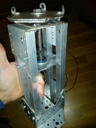
![20150131_152651]() I took a steel plate, gave U-shaped and placed on top of the 4 aluminum bars looking down, so the first part of the vertical axis was ready.
I took a steel plate, gave U-shaped and placed on top of the 4 aluminum bars looking down, so the first part of the vertical axis was ready.The second shaft portion beginning with the other motor plate and the housing, cutting four aluminum profiles 10 x 10 mm length of 15cm and placing them inside the cylinder. to have much more resistance I put two X-shaped pillas at the base, making it tight.
At the end of this vertical axis i cut and placed another sheet steel, for attachment to pillars I used a Meccano brackets.
![]()
-
2Step 2
Joints
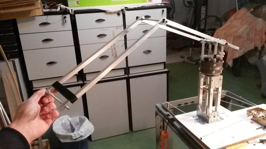
The arm is already taking shape, now the joints. I installed 3 joints, one of those is the wrist that need an entire post.
![20141214_204508]()
At first I thought of making a telescopic extension. The idea was a square profile with a nut anchored go through a cylindrical profile. A threaded rod would rotate to move the square profile.
This system easily solved several problems but getting engines that could move the bar quickly was almost impossible, so I switched to a 3-point joints, hereafter ‘Shoulder’, ‘Elbow’ and ‘wrist’.
![20150208_215339]()
The profiles are rectangular aluminum of 12 x 10 mm.
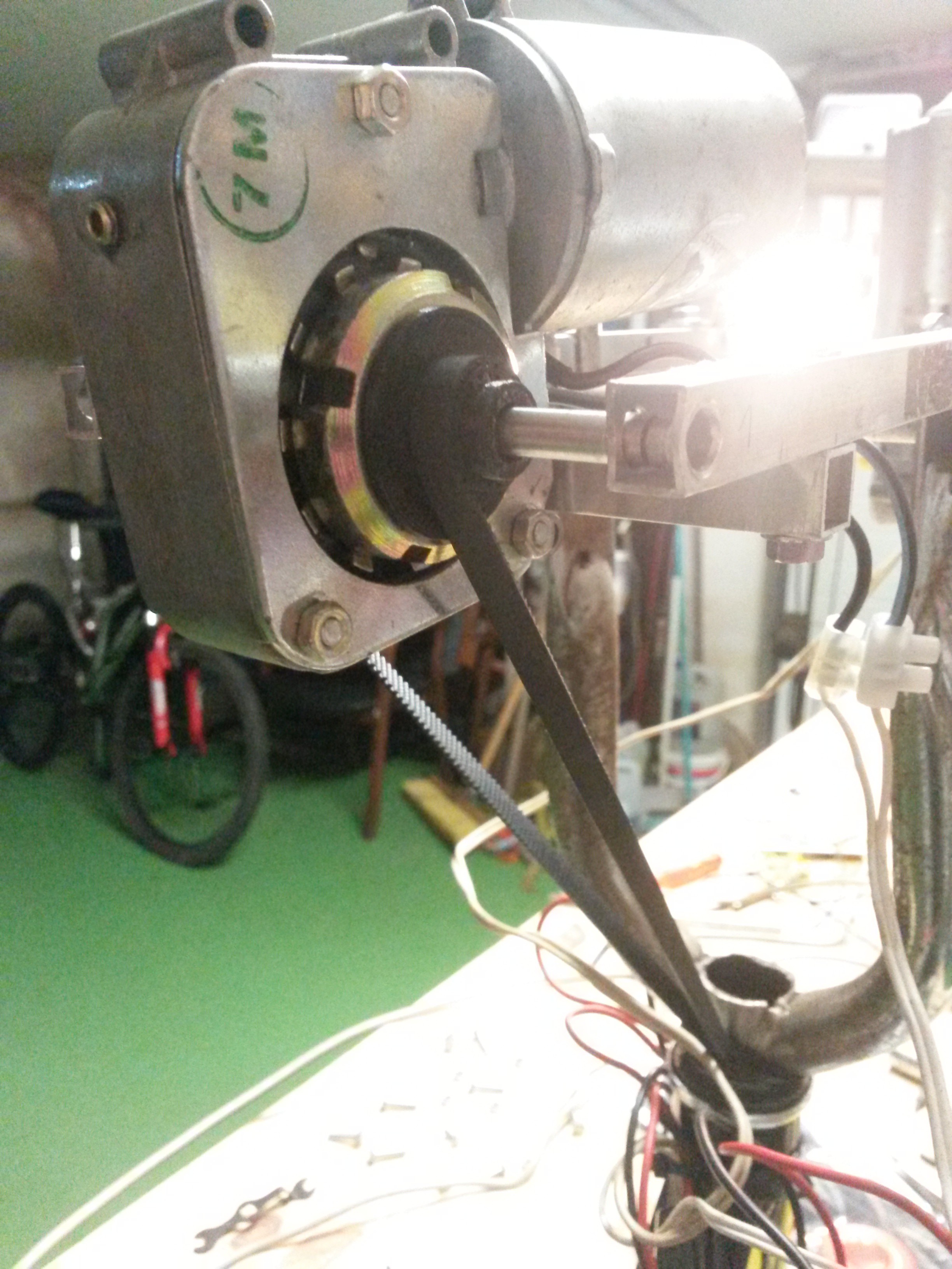
Now that were already in place came the part of the movement .Luckily, a friend had just cleaned the attic and had given me several things, including two power windows car engines. These motors are 12V DC and have the characteristic of having much torque, just what I need.
![20151004_005544]()
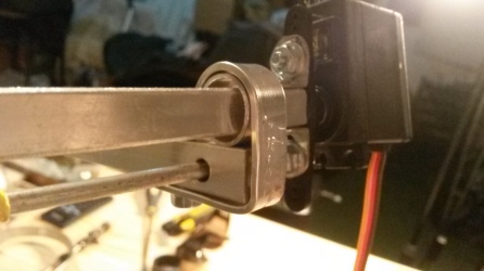
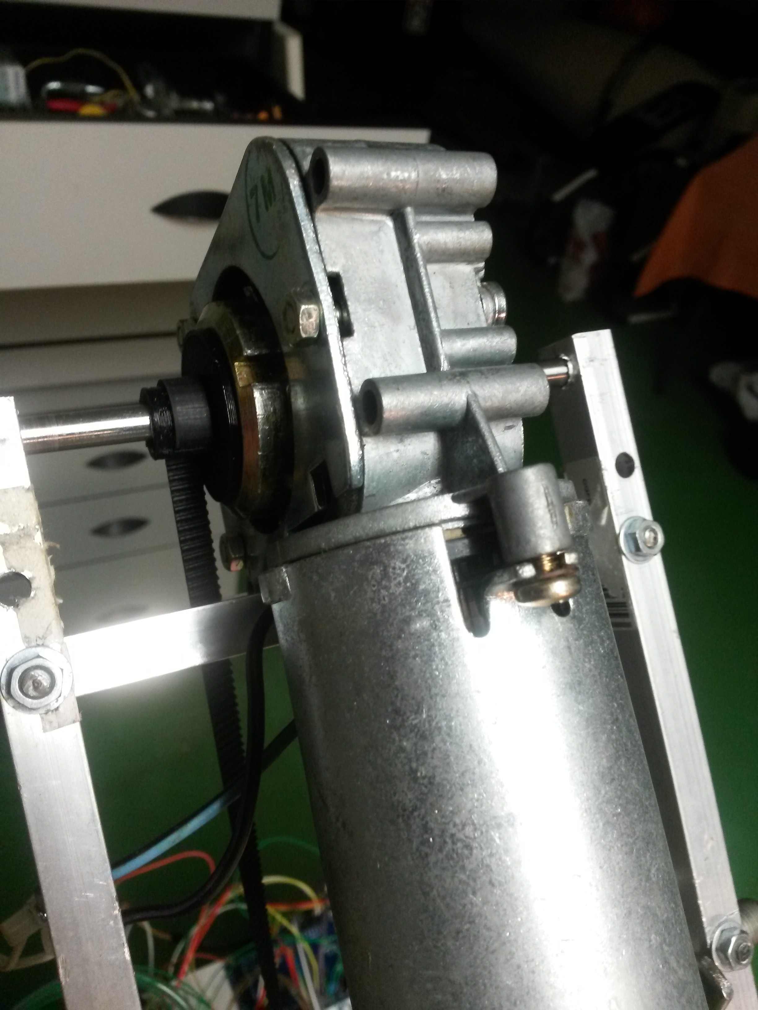
The motors are hooked by aluminum frame to the structure. In the third picture the square frame(which makes motor shaft) inside cylindrical frame. It’s like a tread. This assembly is wrapped by a sheet of aluminum of 10 x 2 mm.
To transmit the movement thought of using ropes, but only temporarily, because they have the disadvantage of stretching the load weight, a situation to be avoided in a system designed to be accurate. In the future they will be changed by metal chains.
And just it left wrist, but that deserves a separate post.
-
3Step 3
Wrist
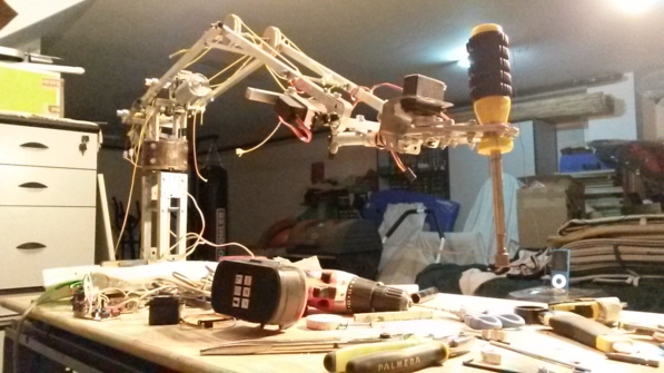
![20150922_215537]() We have reached the last mechanical phase of dimmer, i will explain how I made the wrist.
We have reached the last mechanical phase of dimmer, i will explain how I made the wrist.This part took me a lot of work, since the arm had to pick up one kg but moving with precision. To do this, I designed the wrist with two axes. One of rotation and other to go up or down.
![20150923_162151]()
I joined the clamp (bought by Internet, looking robot gripper) with a square profile of 10 x 10 millimeters. This frame will go inside of a cylindrical frame, and this frame is hold to the other frame that goes up and down.
After this i joined the servos. For vertical movement I used two Hd 1501 MG servos, with a torque of 17 kg-cm, while I used two MG995 servos of 11 kg-cm of torque for rotation.
Finally, I attached Hd 1501 MG servos to the structure and set the MG 995 to the cylindrical frame.
See you soon!
![20151004_005557]()
-
4Step 4
Horizontal movement
Hello there!
![20151128_222627.jpg]()
few days before the OSHWDem still could not take the horizontal movement, so I was trying out some new techniques with the bad luck that one of the most essential parts broke. I tried to replace with two steel plates but did not have the same hardness.
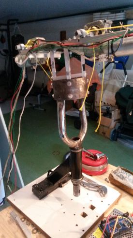
For lack of time I could not make the vertical axis again, so i thougt to use a bicycle fork that was reserved for another project.![IMG-20151101-WA0002.jpeg]() With OSHWDem almost upon grabbed the angle grinder, I cut the part I needed and attach to the base.
With OSHWDem almost upon grabbed the angle grinder, I cut the part I needed and attach to the base.
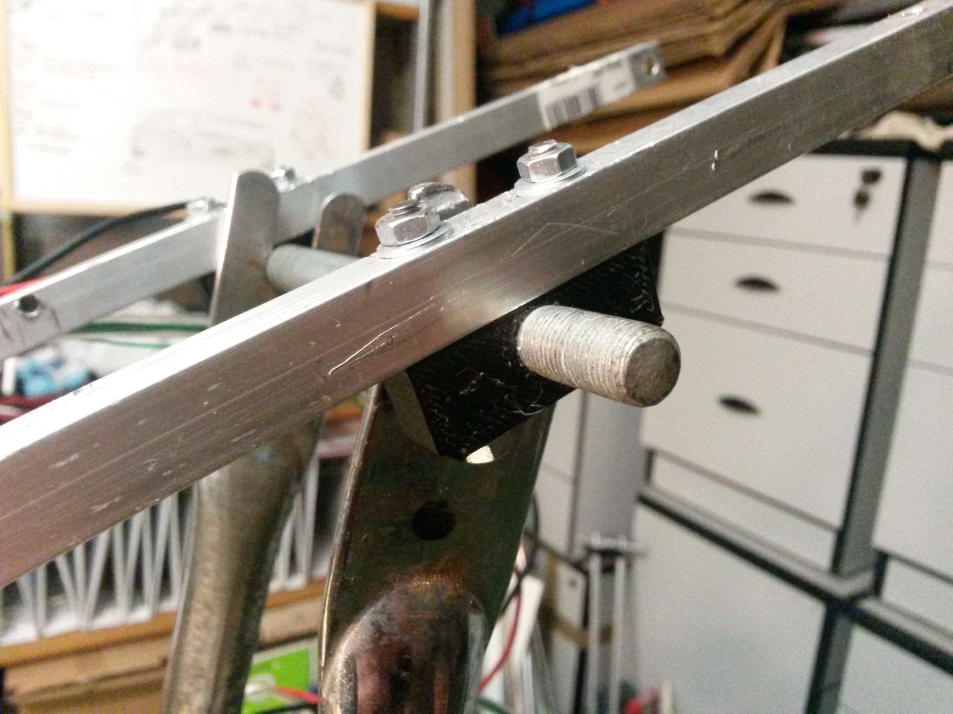
With this new base it could move easily, with the bearings of the fork. Now it was time to think about how to move it… I knew I needed a powerful low-speed motor to not move too fast.
Had an old engine of a broken printer that had long brought Geared shafts, and a further reduction designed with pieces of Meccano. To join this axis with the fork of the bicycle I used a piece made of aluminum foil.
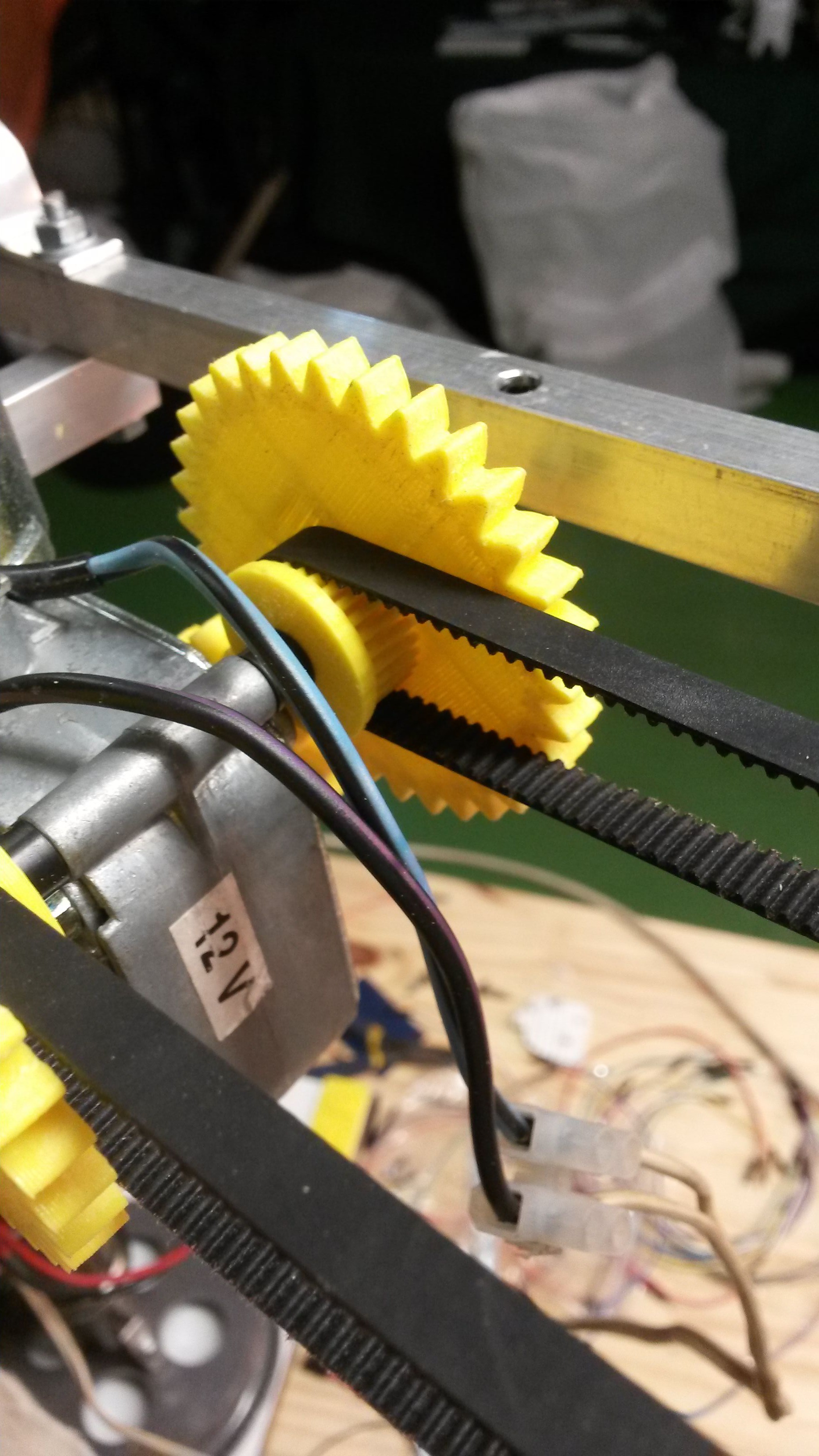
At the end of OSHWDem I could develop a less noisy system, more accurate and consumes less energy (printer engine was 24 V and needed a power supply of 5 A).For this I took a pair of gears with his belt and joined the shaft with aluminum sheets. I use now a MG995 360 degrees servo.
-
5Step 5
Electronic
Electronic is responsible for receiving the signals we send, processes, and acts on the different motors to move DIMER as we want.
Shopping list:
- Arduino Mega
- 2 9g servos
- 2 speed controller h10143
- 2 plate 4 servos / 1 contact
- Several potentiometers 10k ohm
- parallel port
- Wire 1 mm section.
- Data Wire
- Parallel Wire
- Power supply 12 V / 20 Amp
- Power supply 5 V / 3 Amps
- Joystick
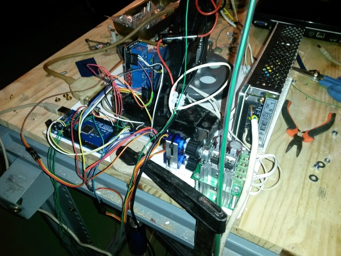
![20151128_210804.jpg]()
I used a usual joystick, I changed all potentiometers for a 10 k to have a more linear signals. The fact of using a parallel port is because i need to get six signals plus 4 power wires and parallel ports have 25 wires.I put a parallel connection to plug and unplug the joystick, so we can transport it in a simpler way.
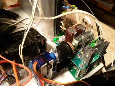
![20151128_210305.jpg]() There are two speed controller to change the speed of the windows motors. To send signals from the Arduino to these drivers I’ve had to use two servos 9g to rotate the drive potentiometer, then the current will go through the relay depending on whether the direction you want to activate the motor.
There are two speed controller to change the speed of the windows motors. To send signals from the Arduino to these drivers I’ve had to use two servos 9g to rotate the drive potentiometer, then the current will go through the relay depending on whether the direction you want to activate the motor.The power supply is 12V is for windows motors, while the 5-volt supply is to a common line of 5 volts to feed the servos, the Arduino and the joystick.
![20151128_210329.jpg]()
The signals to the servo from the Arduino are send from PWM pin. This data line will independently from the power line, to have less noise in the signal. Finally, the wires are fixed to the horizontal joints with flanges.
-
6Step 6
Hello there!
In Christmas I had a little more time to improve DIMER, improvements have been mainly two; motor drivers and two potentiometers to know their position and power programming.
Drivers:
In Bilbao maker fair another maker told me he had just found a few drivers with high power and could be controlled from the aruino directly.
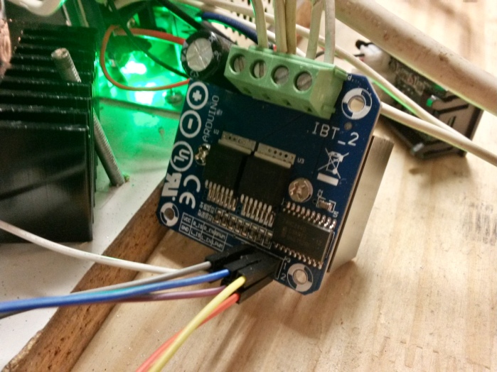
Turns out they were the IBT-2, these drivers can be find on many websites and can get it for about $ 9.
According to the sheet the maximun intesity is 30 amps and 27 volts, also making the change of direction of motor, all directly from PWM.
![20160106_011612_Richtone(HDR)]()
So I bought it and searched for some code to move. it is very easy, just send 0-255 values for PWM channel while the other put it to 0. So I replaced the old drivers quickly, they were much worse, and besides saving me from the servos moving potentiometer of the driver and relays for changing direction. So now the base is clearer.
![20151115_235210]()
(before and after driver changes)
![20160106_011624]()
Potentiometers:
Obviously I need DIMER can be programmed to do repetitive tasks or certain actions, so I needed to know their position at all times. For this I put a few potentiometers in the shoulder and elbow angles, I use potentiometers because they are very easy to use and also none of my angles is greater than 180 degrees.
So put the two he needed, the elbow is much more accessible than the shoulder, since you can tie directly to the shaft as shown in the image.
![20160106_011643]() The shoulder was a little more complicated, finally had to put an aluminum foil and hot glue to secure it to the shaft, this is because they did not have any parts on hand to hook, but I will make a 3D part.
The shoulder was a little more complicated, finally had to put an aluminum foil and hot glue to secure it to the shaft, this is because they did not have any parts on hand to hook, but I will make a 3D part.![20160106_011635]() Here you have the first video I made with the code, it moves from one angle to another of the shoulder.
Here you have the first video I made with the code, it moves from one angle to another of the shoulder.The code is very simple, you you indicate that joint angles and want to move, with a couple of simple loops DIMER knows how much has to move and in which direction. Part I found it online and then adapted it to my needs.
I leave here, I probably another way to do it more efficiently to happen, but for now it works and part of debugging code and the will to finish it all.
With this development is DIMER updated.
See you soon!
// Only share Void loop, the setup is simply declare variables and start the Serial 9600.
//lectura posicion codo
posicion2 = map(analogRead(A4), 0, 1023, 180, 0);
posicion3 = map(analogRead(A7), 0, 1023, 0, 180);
Serial.print(" H ");
Serial.print(posicion3, DEC);
Serial.print(" C ");
Serial.println(posicion2, DEC);//programacion movimientos:
if(Serial.available() >= 1)
{
/*
1- Leer un numero entero por serial
2- Calculamos su modulo por 10 (sera el numero del motor)
3- Dividir el entero inicial por 10
4- Lo que quede, sera la posicion del motor
*/
enviado = Serial.parseInt();
num = enviado%10;
enviado = enviado/10;
posicion = enviado;//aqui bajamos el codo hasta que llega al angulo correcto
if(num == 1) //quiere decir que queremos mover el codo
{
if(posicion>posicion2){
do{
analogWrite(LPWM_Output, 0);
analogWrite(RPWM_Output, 50);
posicion2 = map(analogRead(A4), 0, 1023, 180, 0);
Serial.print("bajando hombro ");
Serial.println(posicion2, DEC);
}
while(posicion2 < posicion);
}//aqui subimos el codo hasta que llega al angulo correcto
if(posicion<posicion2){
do{
analogWrite(LPWM_Output, 50);
analogWrite(RPWM_Output, 0);
posicion2 = map(analogRead(A4), 0, 1023, 180, 0);
Serial.print("subiendo codo ");
Serial.println(posicion2, DEC);
}
while(posicion2 > posicion);
}//aqui paramos los motores al llegar al angulo correcto
analogWrite(LPWM_Output, 0);
analogWrite(RPWM_Output, 0);
}if(num == 2)//quiere decir que qeuremos mover el hombro
{//aqui bajamos el hombro hasta que llega al angulo correcto
if(posicion>posicion3){
do{
analogWrite(LPWM_Output2, 0);
analogWrite(RPWM_Output2, 50);
posicion3 = map(analogRead(A7), 0, 1023, 180, 0);
Serial.print("bajando hombro ");
Serial.println(posicion3, DEC);
}
while(posicion3-5 < posicion);
}//aqui subimos el hombro hasta que llega al angulo correcto
if(posicion<posicion3){
do{
analogWrite(LPWM_Output2, 50);
analogWrite(RPWM_Output2, 0);
posicion3 = map(analogRead(A7), 0, 1023, 180, 0);
Serial.print("subiendo hombro ");
Serial.println(posicion3, DEC);
}
while(posicion3-5 > posicion);
}
//aqui paramos los motores al llegar al angulo correcto
analogWrite(LPWM_Output2, 0);
analogWrite(RPWM_Output2, 0);
}//aqui paramos en caso de emergencia
if(num == 3) // parar todo
{
analogWrite(LPWM_Output, 0);
analogWrite(RPWM_Output, 0);
analogWrite(LPWM_Output2, 0);
analogWrite(RPWM_Output2, 0);
}}
-
7Step 7
Adding some 3D parts
I bought a 3D printer and started to design lots of pieces, i tried freecad, cause it's very easy, and then i discover openSCAD, so i studied how it works an desgin my own gears to DIMER, here's my final test, it's an example with 10% refill but it works great.
![]()
![]()
-
8Step 8
Improving accuracy
Hi everyone!
Since the last video (programmed movements) I've been thinking that had very little precision when lowered the arm. Analyzing the movement
![20160413_151636]() discovered that the craft that i made with two aluminum profiles were fine for a pinch, but it turns out that after many hours of use rubbing causes a lot of wear.
discovered that the craft that i made with two aluminum profiles were fine for a pinch, but it turns out that after many hours of use rubbing causes a lot of wear.So I took the piece that had previously made with profiles and put the shoulder directly attached to a spindle and this supported directly on the fork as you see in the picture.
Then I removed the motor shaft and designed one to print it in 3D. To put up with all the s
![20160420_140854]() trength to raise the arm, I made hollow. Inside is a metal bar I got from a printer. Besides pulling straps instead of ropes, this also gives a more fluid movement
trength to raise the arm, I made hollow. Inside is a metal bar I got from a printer. Besides pulling straps instead of ropes, this also gives a more fluid movementThis way is now mounted, with much more precision but still can improve a lot.
![]()
![]()
![]()
D.I.M.E.R PROJECT 6 DOF Robot Arm
This is my robot arm, with recycled materials, can pick 2 Kg and costs around 100$
 I used a base to anchor legs of a garden arbor and cut one aluminum profile 20 x 20 mm 1 meter long into 4 sections. I screwed these sections to the base and attach to a table, which in theory would be provisional.
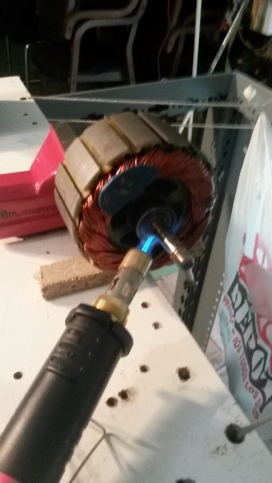 I took a steel plate, gave U-shaped and placed on top of the 4 aluminum bars looking down, so the first part of the vertical axis was ready.
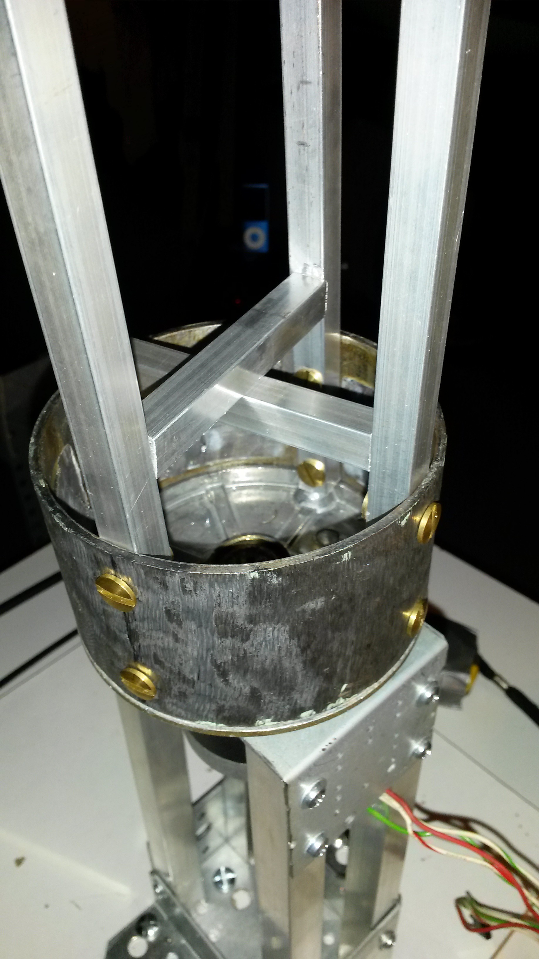


 We have reached the last mechanical phase of dimmer, i will explain how I made the wrist.
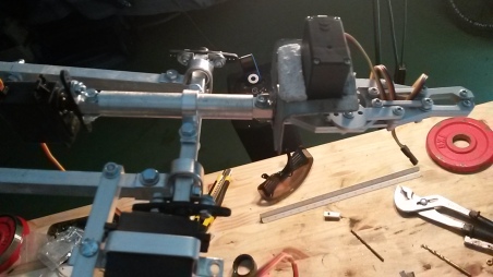
 With OSHWDem almost upon grabbed the angle grinder, I cut the part I needed and attach to the base.
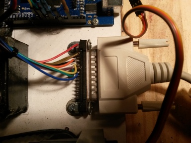
 There are two speed controller to change the speed of the windows motors. To send signals from the Arduino to these drivers I’ve had to use two servos 9g to rotate the drive potentiometer, then the current will go through the relay depending on whether the direction you want to activate the motor.
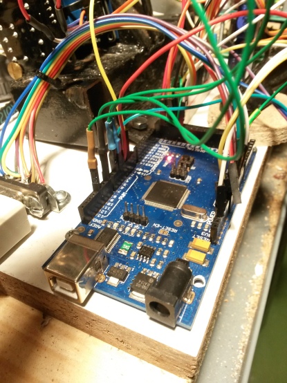

 The shoulder was a little more complicated, finally had to put an aluminum foil and hot glue to secure it to the shaft, this is because they did not have any parts on hand to hook, but I will make a 3D part.
 Here you have the first video I made with the code, it moves from one angle to another of the shoulder.
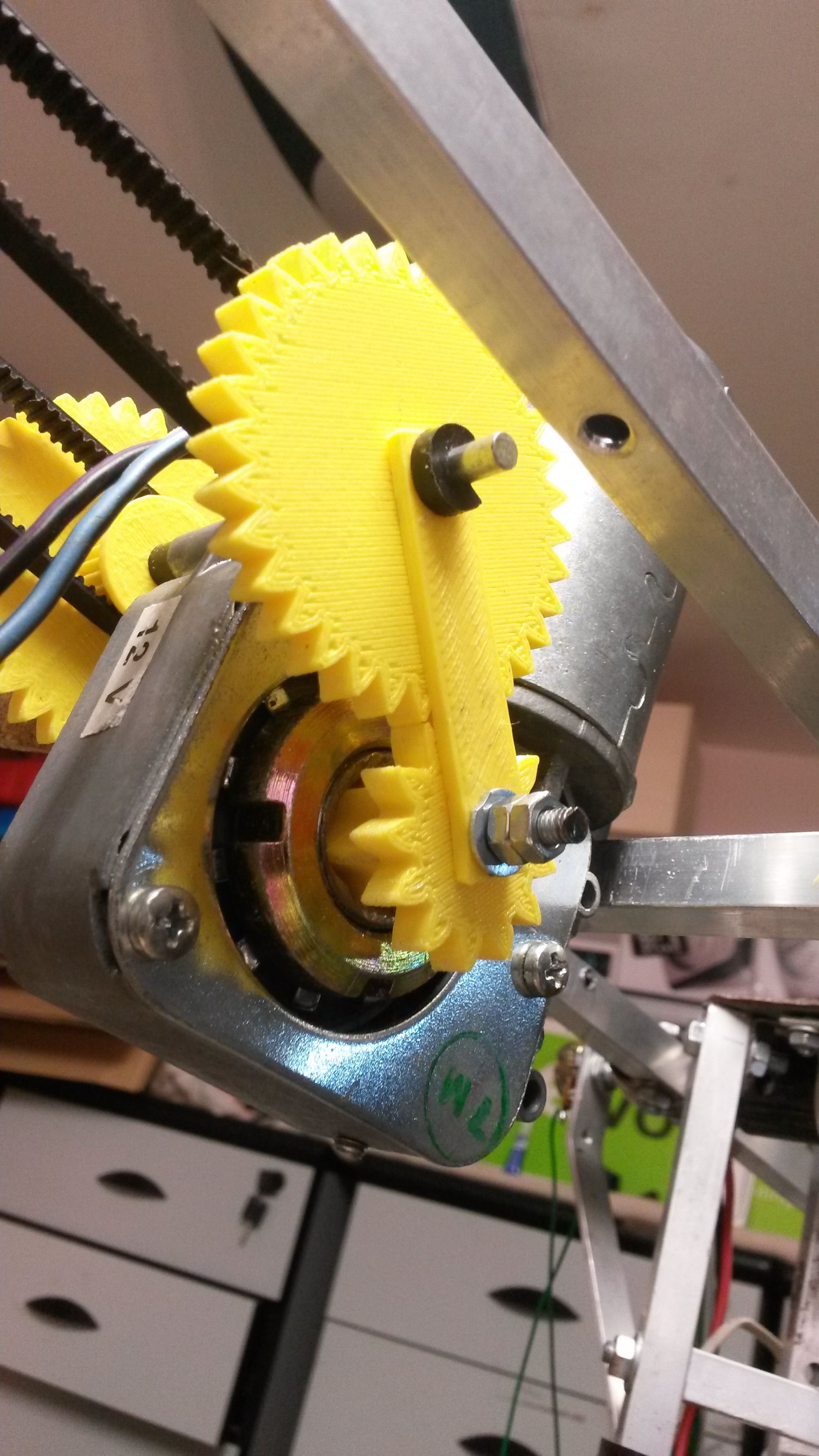
 discovered that the craft that i made with two aluminum profiles were fine for a pinch, but it turns out that after many hours of use rubbing causes a lot of wear.
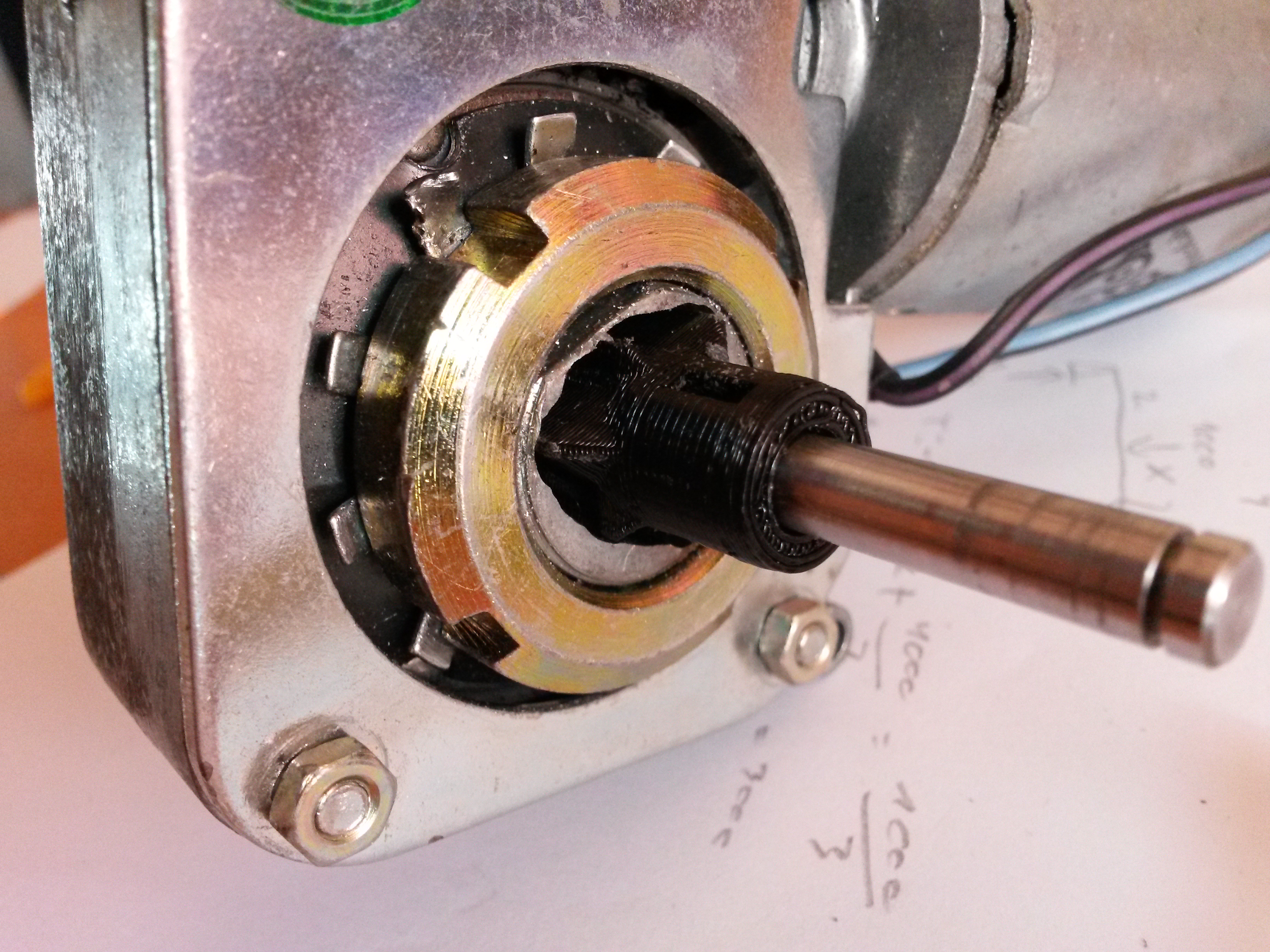 trength to raise the arm, I made hollow. Inside is a metal bar I got from a printer. Besides pulling straps instead of ropes, this also gives a more fluid movement
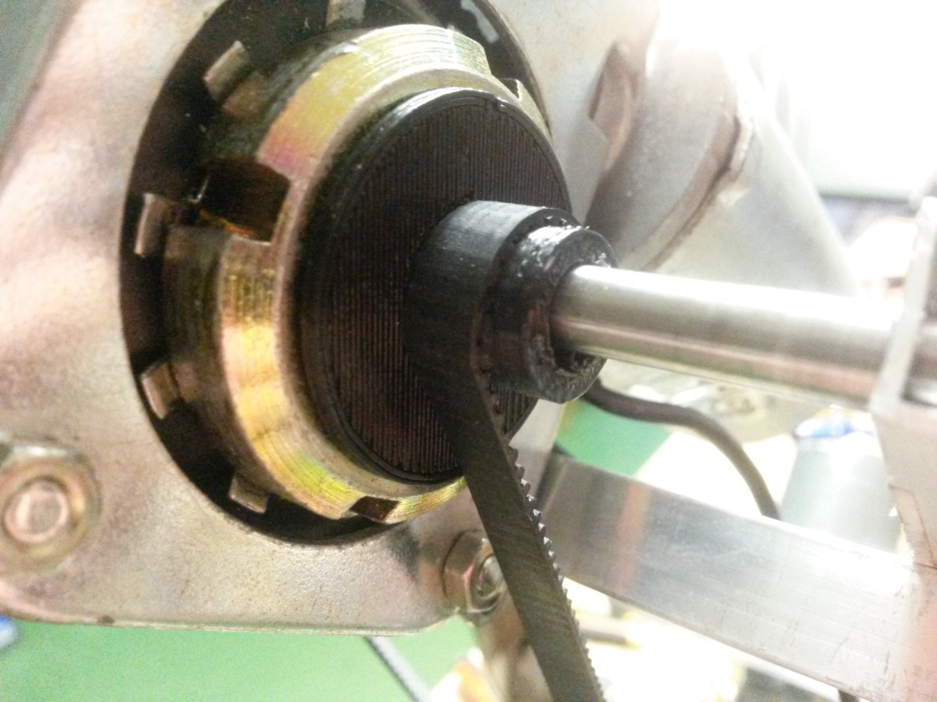
Discussions
Become a Hackaday.io Member
Create an account to leave a comment. Already have an account? Log In.