Alex
Alex-
tiny LEDs
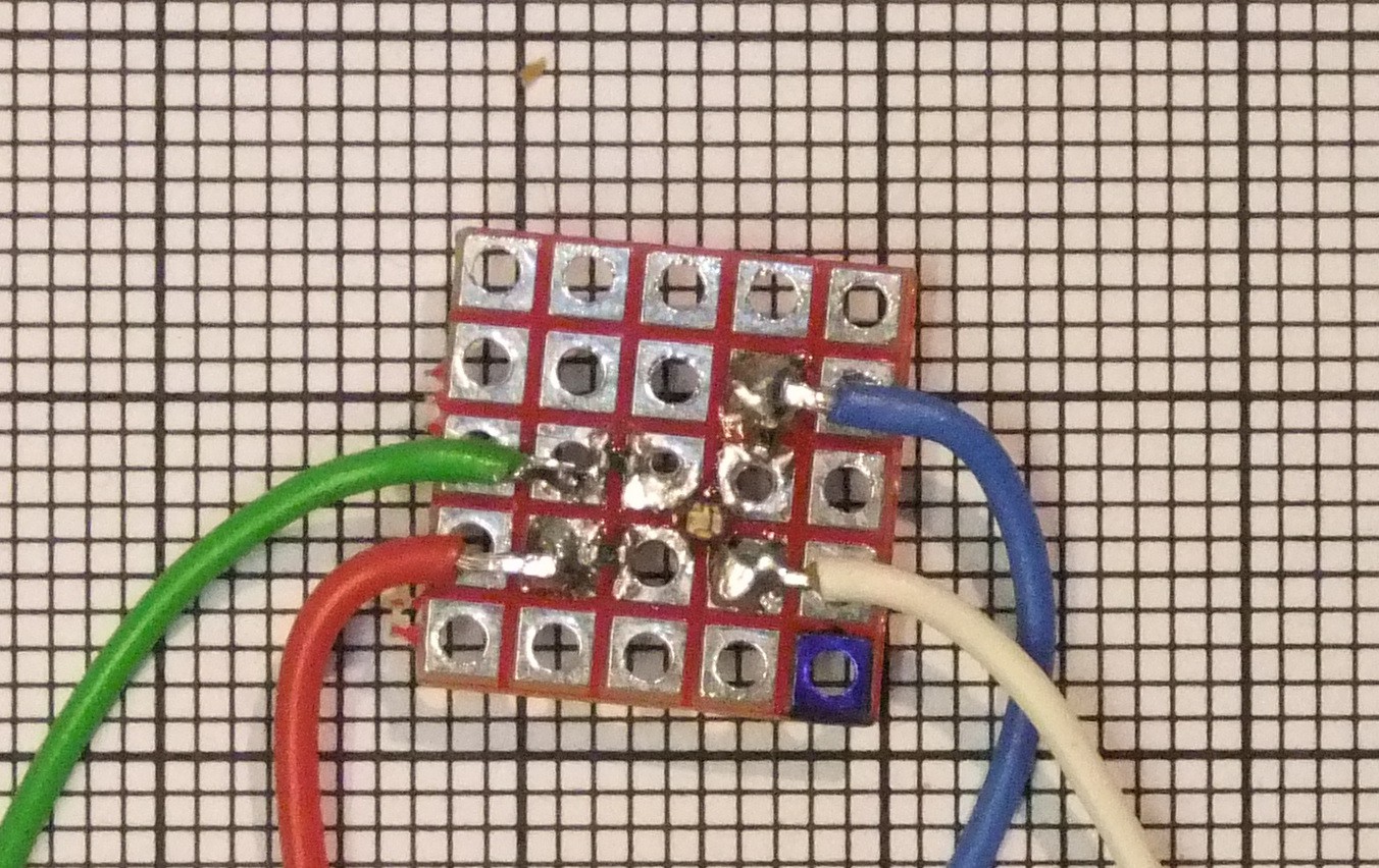
03/11/2016 at 15:00 • 2 commentsin reallife these 0404 RGB LEDs are very very small: (the Grid in background is 1mm)
![]() soldering this one on the bread board did work unexpected easy. The PCBs for this project did not arrived yet, but the stencil did arrived. I am happy about the decision ordering the stencil. With it soldering the LEDs could be possibel.
soldering this one on the bread board did work unexpected easy. The PCBs for this project did not arrived yet, but the stencil did arrived. I am happy about the decision ordering the stencil. With it soldering the LEDs could be possibel. -
PCBs, stencil and parts orderd
02/22/2016 at 16:31 • 7 commentsI did just orderd the last missing parts. Now everything should be ordered to built one (or two perhaps)! I did also ordered a SMD stencil for the first time. With this the solder paste dispensing should be faster and better. And only the LEDs do have 512 pads. For the PCB I did chose black solder mask this time to get high contrast to the LEDs.
-
More final PCB design & Changed number of LEDs
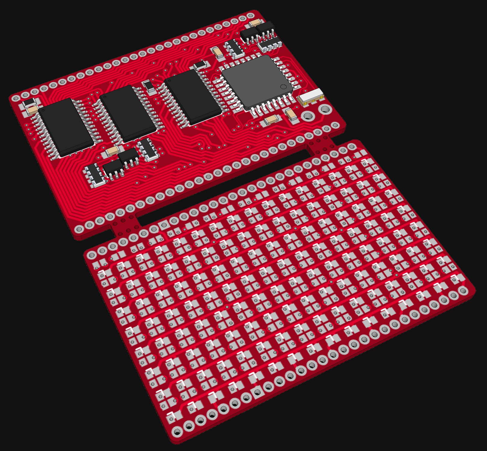
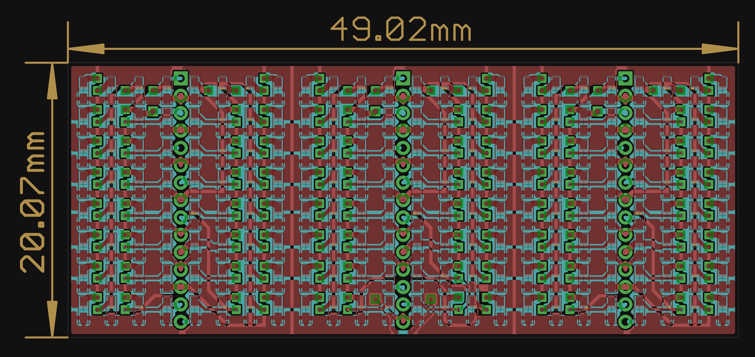
02/20/2016 at 16:57 • 1 commentI did decide to use just 128 RGB LEDs in a 8*16 Matrix. This reduces the the circuit to drive them. I think I will use one 16Bit shift register (MBI5026 or compatible) for each color and multiplex over the lines. The current for each color can than bes set independent.
For controlling everything there is as Atmega xx8 on the PCB. I think I will use a ATmega328p, because they can run at 20MHz and I do have some left. This panel does fit in 5*5cm so PCB manufacturing is cheap. The two PCBs wil be stacked on each other.![]()
I will update details and description of this project to this revison. I think this will be near the final one. At least I am not planing to change the number of LEDs. -
Idea: More LEDs - More Colors
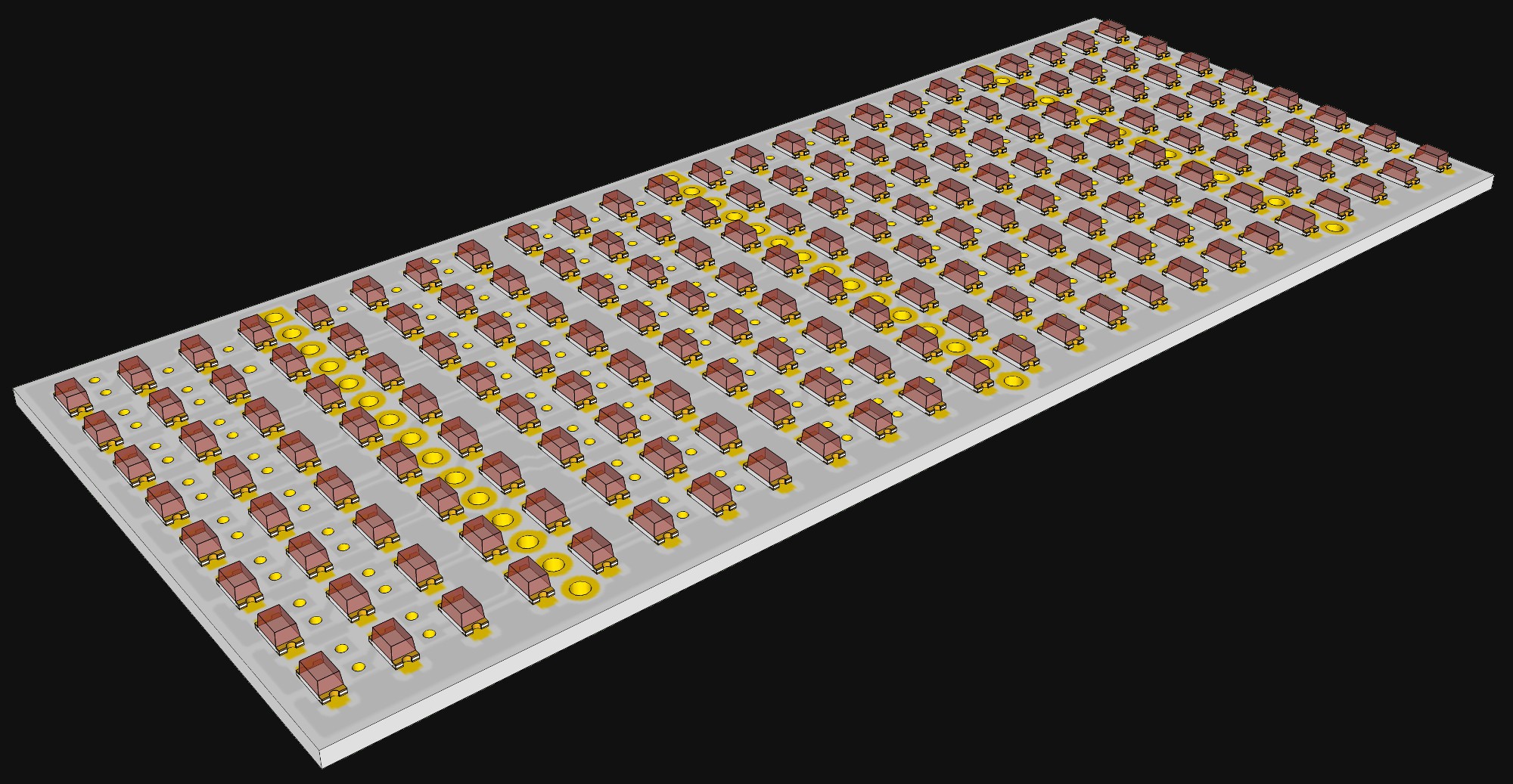
02/15/2016 at 20:13 • 1 commentSome time ago while talking with someone else about this project, the idea came to use RGB LEDs. And there are small suitable RGB LEDs available: 0404 RGB LEDs. So this is what I came up with: 21*8 RGB LEDs ( =168 RGB LEDs or 504 single LED chips):
![]()
Problem here is how to control so many LEDs? I am not sure yet but I am planing to multiplex the lines. And driving the columns via some (21*3=63 Bit!) shift registers. I am also thinking of using a Microcontroller which is faster than a ATmega to get a acceptable refresh rate on the Matrix.
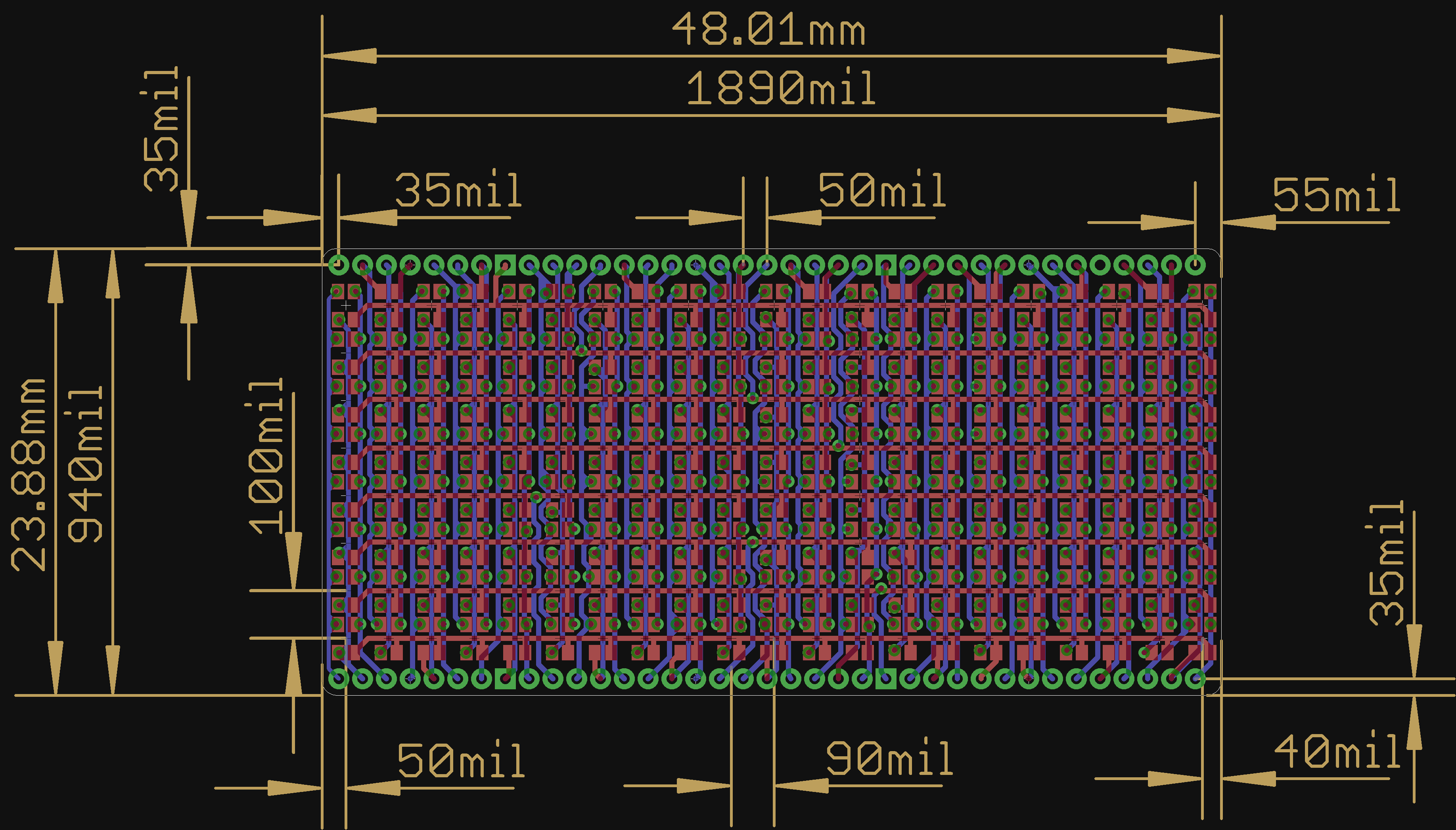
The PCBs measurements did not changed much. The goal is still to fit this and a control PCB of the same size into 5x5cm:
![]()
Because this project is still in early stage it is possible that I will return to a single color version ( or never built one ).
-
further progress
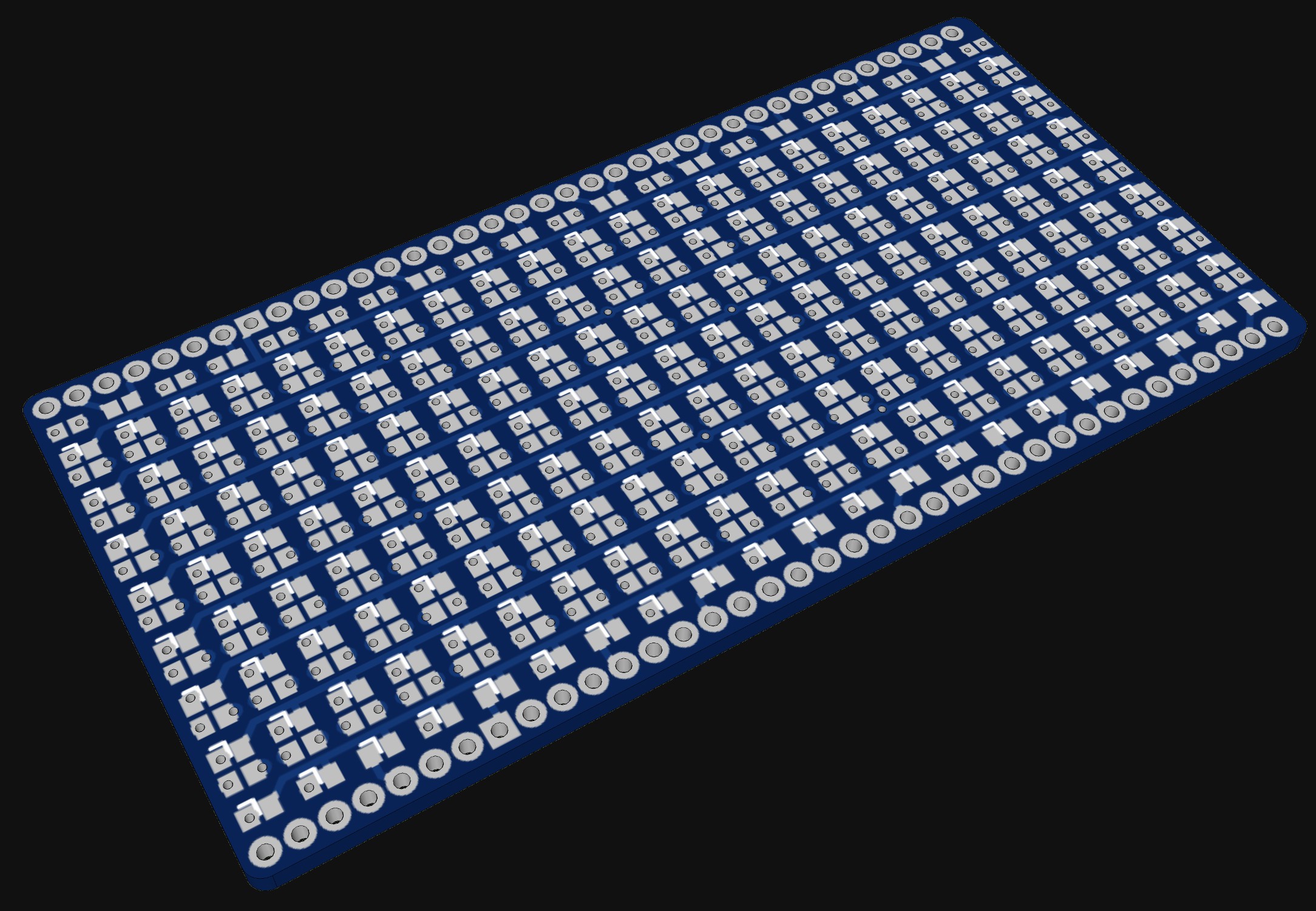
12/22/2015 at 16:46 • 0 commentsI did change the number oft LEDs. I think I will use even more than 140. I do now think I will use 192 LEDs arranged in a 24x8 matrix. The LED-PCB could than look like this:
![]()
![]()
This would still fit including a control PCB of the same size inside 5cm x 5cm. I do also have some first idea about this control PCB. I did found two LED drivers witch I could imagine to use for that:
- 24 channel LED sink driver controlled by built in 24 Bit shift register. With this I would power the columns. The row would be multiplexed and driven by discrete transistors. Possible parts:
- STP24DP05BTR
- TLC5947
- MBI5368
- Two 16 channel LED driver (8 outputs unused) . Similar as above but maybe cheaper possible parts:
- MBI5026
- TLC5928 / TLC59282 / TLC5926
- MAX6971
- STP16C596
- A6279
- Three 8 channel driver similar as above
- MBI5168 ... MBI5171
- CAT4008
- TLC5916/7
- AS1109
- HT1632C: all in one driver for big LED matrix. Controlled by SPI interface.
Additional to the LED driver I would also include an microcontroller.Although this would be optional if using the HT1632C. But so you can implement stand alone applications and different interfaces (uart, i2c, parallel). Depending on the LED driver and interfaces (== the number of needed IOs / peripherals) I will probably use an ATmega 8a, 328p, 16 or 32.
- 24 channel LED sink driver controlled by built in 24 Bit shift register. With this I would power the columns. The row would be multiplexed and driven by discrete transistors. Possible parts:
384:LED
Mini (1.44'' x 0.94'' or 24mm x 37mm) 8X16 RGB LED Array. 128 RGB LEDs with three LED chip each gives 384.
 soldering this one on the bread board did work unexpected easy. The PCBs for this project did not arrived yet, but the stencil did arrived. I am happy about the decision ordering the stencil. With it soldering the LEDs could be possibel.