-
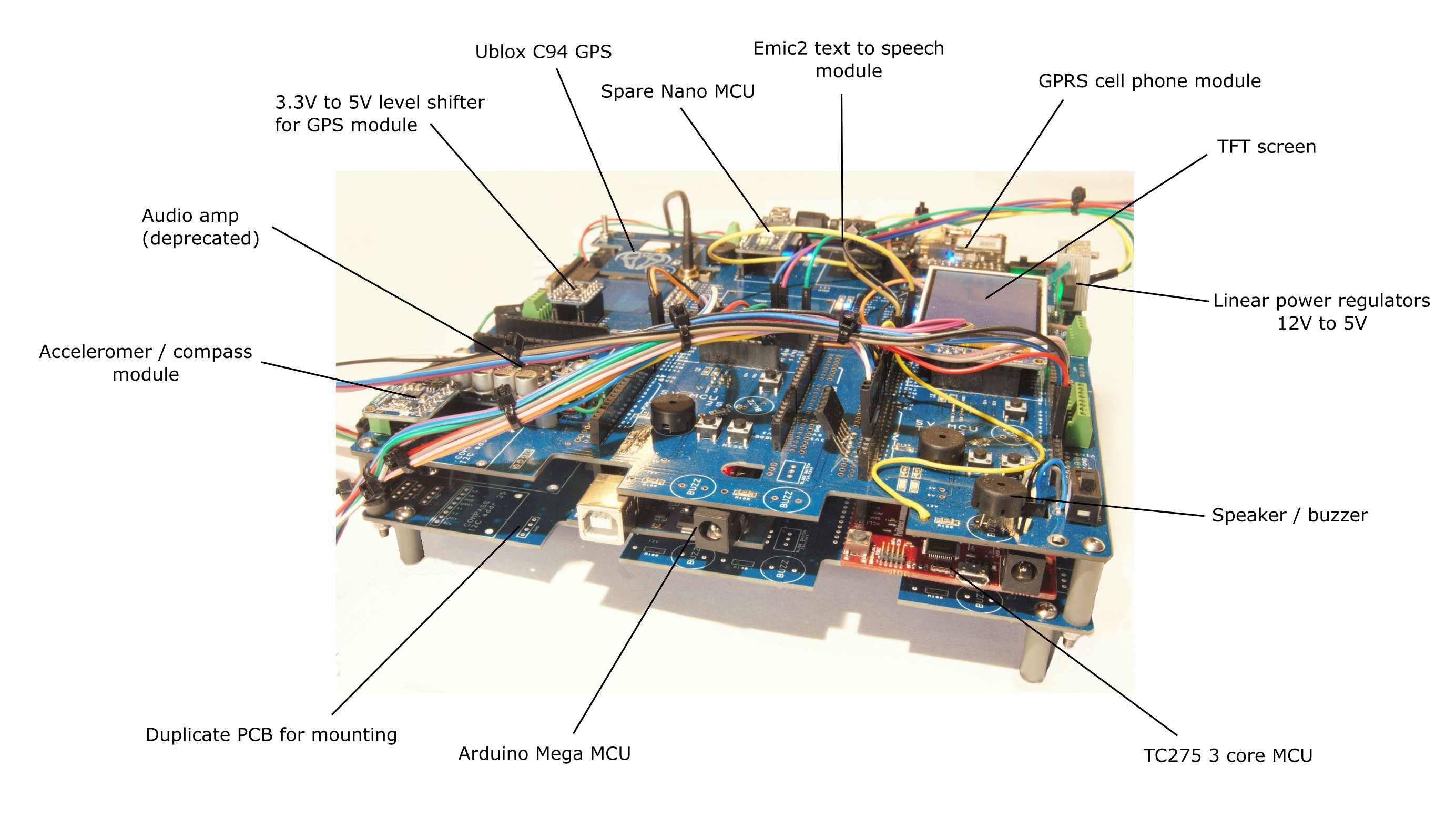
1Annotated Diagram
![]()
-
2Surface Mount Soldering
![]()
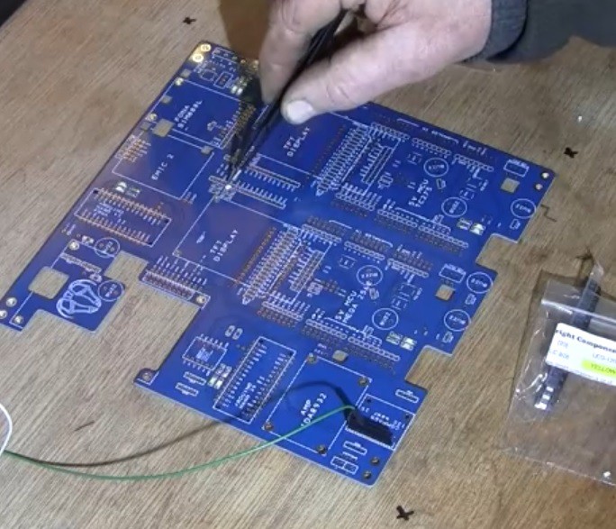
First thing is to solder all the 1206 components - resistors, LEDs and capacitors. No stencil is required - just a small amount of solder paste and a reflow heat gun. Fear not - soldering this size SMT is easy!
Sometimes it's difficult to spot the polarity of the LEDs so it's a good idea to have a flying 5v power supply to check that the LEDs work before applying the final heat. Lay the LED in the solder on the pads and test they work.
The green LEDs require a higher resistor than the others so 2k is used with these and 1k with the others.
The 0 ohm resistors can be left off - they give options to connect the SIM800 to the MEGA 2560 instead of a NANO. The 2560 tends to be more stable in operation.
-
3Mount the Buzzers, switches, regulators, screw terminals
![]()
![]()
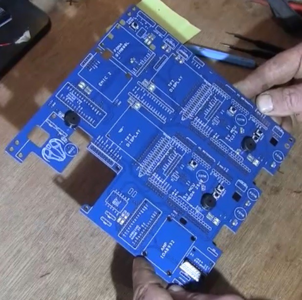
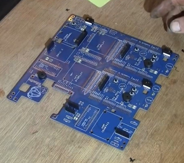
These items are very robust, so need to be soldered next. Screw connectors are very useful where there is any vibration in the machine as they are pretty solid. Otherwise there are female connectors for flying leads on the stackable pins on the MCUs. The buzzers require 100 ohm resistors to protect the MCU from supplying too much current and burning out the pin circuit.
There are some random locations for ground and 5v screw terminals which are very useful. The 12V screw terminals are all 5.08 mm pitch.
NB. The Ublox Rover module can be connected to the PCB 12v supply or to a 10 to 30 VDC battery which is useful for keeping it 'live'.
-
4Wire on the SIM800 battery
![]()
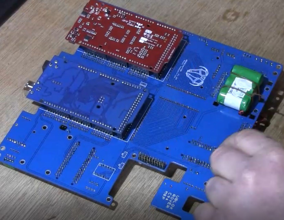
The SIM800 wont work without a battery and it is wired onto the underside of the PCB, but not connected to the PCB ie not soldered, just tied on. There are special holes in the PCB for this.
-
5Solder on the Headers
![]()
![]()
The headers for the Nanos, compass, Ublox, Emic TFT and SIM800 are all standard male - female 0.1" pitch and are relatively easy to solder - so do these first.
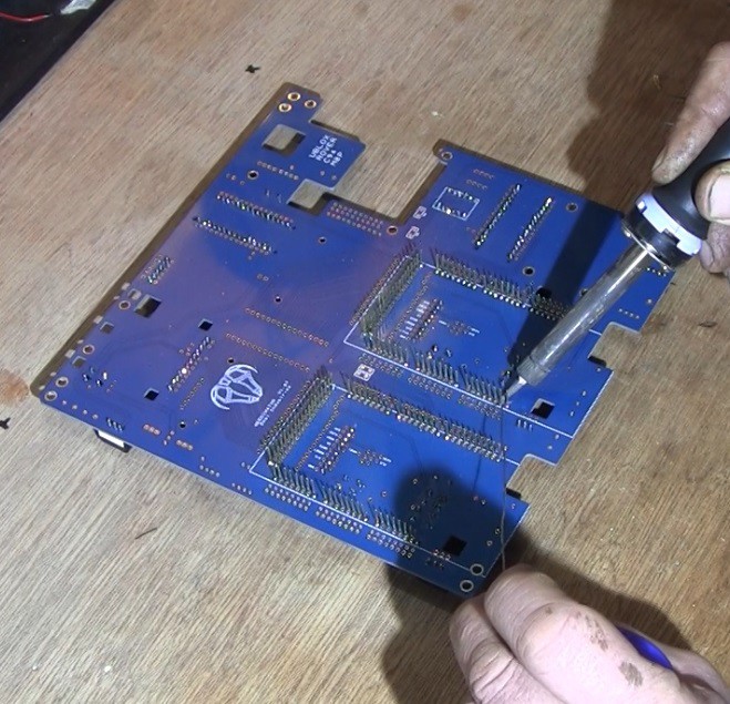
The main 2 MCUs push onto the underside of the PCB and the headers for the MEGA 2560 and TC275 are more difficult and harder to find. They are special stackable male - female headers with long male legs that go through the PCB and allow the MCUs to be attached on the lower side. They are very difficult to solder and it's strongly advised to practise on a spare unpopulated PCB until the MEGA 2560 pushes on and off with ease. To make things even more difficult, there's some 6 way male - female headers in the middle of the MCU footprint that also need soldering. These headers MUST be compatible with the MCU pins and are the same type used on the Nanos etc - don't buy the 2 x 3 blocks with round holes!
Solder the stackable headers one MCU at a time as it's easy to bend the pins when trying to fit each MCU. Get an old MEGA 2560 and squirt WD40 into the female sockets and use this to 'ease' the pins by attaching / detaching a few times. Finally, fit the TC275, which needs an incredible amount of care as - trust me - it's very easy to crack the main chip. This chip covers a very large amount of surface area on the board so if you bend the board - ping - you crack the chip! ....... And these boards are very expensive. It took me about 2 hours just to attach these two MCUs on the last build.
The PCBs can be tested at this stage. First check there are no shorts to ground by checking resistance between 5v to ground and then 12V to ground. 12V to ground should give about 4000 ohms.
-
6Bolt on Modules
![]()
The Ublox bolts onto the underside of the PCB and all the others on the top. Push them all into place and check that they work OK. The TC275 TFT screen will not work unless the EMIC2 serial1 in AND out are connected. Serial 1 is normally right next to the SDA pins, but may also be denoted RX2 / TX2 on the PCB itself. A bit of trial and error may be needed to get the EMIC2 to work properly. Sin connects to TX and Sout to Rx.
Once everything is working, use 3mm and 2mm bolts and appropriate plastic spacer cylinders to secure the modules in place. The EMIC2 has no bolt holes :(
-
7Attach to Motor Drives
The motors themselves each have their own power supplies and sophisticated 'Drives' which are normally interfaced to the MCUs by 5V PWM logic. A basic test can be done with just one connection to 'STEP' or 'PULSE' on the drive to the relevant pin on the MCU ... and ground to ground. Make sure that the motor is securely clamped / bolted down and test! Some of the more complicated servo motors need to be tuned, but that is another story!
-
8Set up Ublox Base and Rover Devices
![]()
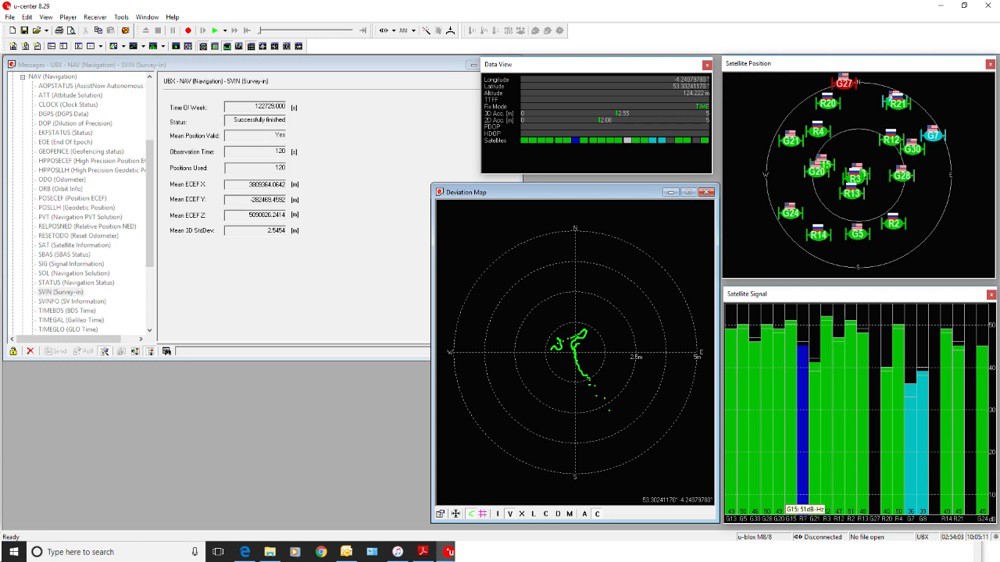
The base station remains static in one location and transmits a signal via a radio link to enable error correction for the Rover, as long as the radios are in range of each other. Ublox supply an excellent bit of software for showing satellite information and configuring the two devices (C94 M8P). For convenience, I've created 3 configuration files that can be uploaded with UCenter software straight to the devices.
For an initial test, use the quick 2 minute 'survey in' file: https://cdn.hackaday.io/files/900573852998688/Ublox%20Base%20%202%20minutes.txt
For accurate, repeatable, results use the 24 hour version - be warned - it takes 24 hours before you can use the devices! : https://cdn.hackaday.io/files/900573852998688/Ublox%20Base%20%2024%20hours%20.txt
The Rover uses the same config file whatever: https://cdn.hackaday.io/files/900573852998688/Ublox%20Rover.txt
Just upload the files into non-volatile flash using tools > GNSS config > GNSS > FILE. If you want to see the actual survey in status go to View > Messages > UBX > NAV > SVIN and right click 'enable'.
It's worth mentioning that these Ublox devices are 3.3V logic and using them on a 5V MCU without logic level shifters may destroy them.
-
9Arduino MEGA 2560 code
The code for this MCU is here: https://cdn.hackaday.io/files/900573852998688/Weedinator_NMEA_MEGA_36.ino
This MCU currently hosts a magnetic compass and receives NMEA data from the Ublox network. It's connected to the TC275 MCU as a slave on I2C bus. There are numerous libraries required to run this code, including NeoGPS by SlashDevin : https://github.com/SlashDevin/NeoGPS
The code also accepts long and lat data from the GPRS module and calculates a heading and distance for transmitting onto the TC275 master.
It's very much in development so please expect major changes in the near future!
Upload the code and libraries to the MCU in the normal way. The orange LED and buzzer indicate that valid, uncorrupted, NMEA data has been received and the blue LED flashes to indicate that the MCU is still working.
-
10Arduino Nano Code
This MCU controls the SIM800 GPRS module, sending / recieving 'AT' commands and downloading data from an online database. Code is here: https://cdn.hackaday.io/files/900573852998688/Weedinator_Fona_Nano_13censored.ino
It also receives data from the TC275 regarding which waypoint is currently active so that it can get the correct line of information from the table in the database. It then sends details of latitude and longitude to TC275.
Autonomous Agri-robot Control System
Controlling autonomous robots the size of a small tractor for planting, weeding and harvesting
 Capt. Flatus O'Flaherty ☠


Discussions
Become a Hackaday.io Member
Create an account to leave a comment. Already have an account? Log In.