Laetitia BEL
-
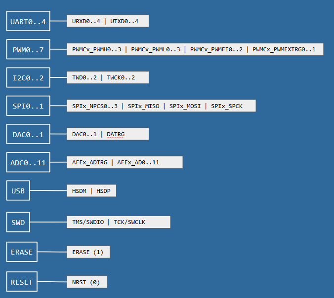
SAME70 USED SIGNALS
03/21/2018 at 16:06 • 0 commentsThe list of signals used in the projects, I didn't describe them before, while using the schematics.
They are eigther exposed using connectors, or simply linking modules.
For almost all the signals the Vcc=3V3.
Mapping of the DAC and ADCThe selected mapping of I2C/UART/SPI
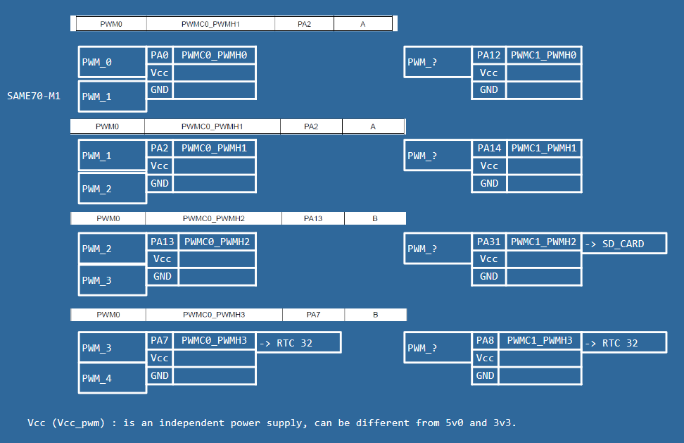
Mapping of the PWM
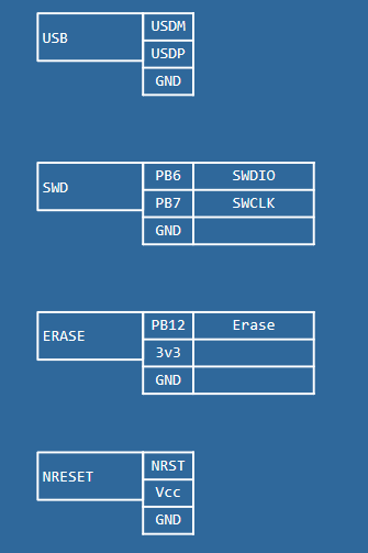
And now the USB, SWD, Erase button and Reset button.
I forgot to point the fact that all the SAME70 will have their SWD port for debuging. -
DRONI SAME70Pi / 1.ELECTRONICS / REMOTE CONTROLLER
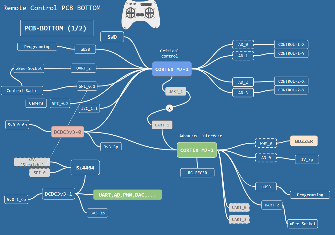
03/21/2018 at 00:38 • 0 commentsThe idea is to have a hackable remote controller with a bunch of functionnalities without constraints on the real time transmission for manual control.
Again there will be SAME70 every where!
The remote controller will have two PCBs TOP and BOTTOM, same principle.
Only this time we put all the power, calcullation and communication modules in the BOTTOM PCB.
We the TOP PCB for buttons/leds/stick .
We keep almost the same architecture.
Behind this choice is having the same SDK that can program the drone and also the remote controller.
The remote controller will be programmed using the uUSB (x2) in the board.
It will be possible to plug the remote controller to the compute to exchange data (route map, instructions,...)
We use the same LiPo 11v1 but with less power.
The rational behind the 11v1 is the use in case of camera feed reception.
We use the same architecture as the BOTTOM PCB of the flying part.
You can power the remote controller using the uUSB if plugged to a computer (not the video part).
The link between the PCB TOP and BOTTOM of the remote controller is done using a PFC, not decided yet if it is a 30pin or 22pin. Let's assume 30pin and check during the detailed design if things go ok.
The sticks will be directly plugged to the PCB BOTTOM.
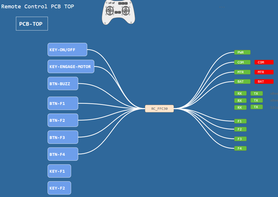
The TOP PCB will display some LEDs and have some functional buttons.
Display:
- Battery status
- communication status
- motors armed
- ...
Buttons:
- on/off drone
- buzzer
- arming the motors
-.... -
DRONI SAME70Pi / 1.ELECTRONICS / BUZZER & MISC
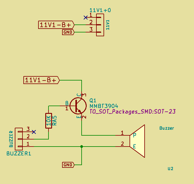
03/21/2018 at 00:23 • 0 commentsBZZZZZZ
I also added a connector for 11v1 in case I need to power a camera with analog feed transmitter, or simply a feed transmitter to the Compute Module.
-
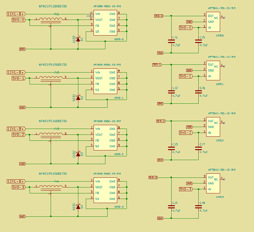
DRONI SAME70Pi / 1.ELECTRONICS / DC CONVERTERS (5V0/3V3)
03/21/2018 at 00:19 • 0 commentsThe PCB BOTTOM provides 5V0 and 3V3 from the LiPo.
I use a bench of DC converters for that.
I put filters at the input of the DC converters to avoid the noise coming from the motors consumption.
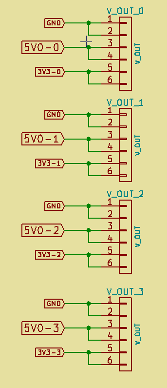
The 5V0 and 3V0 are sent to the TOP PCB using 6pins connectors -
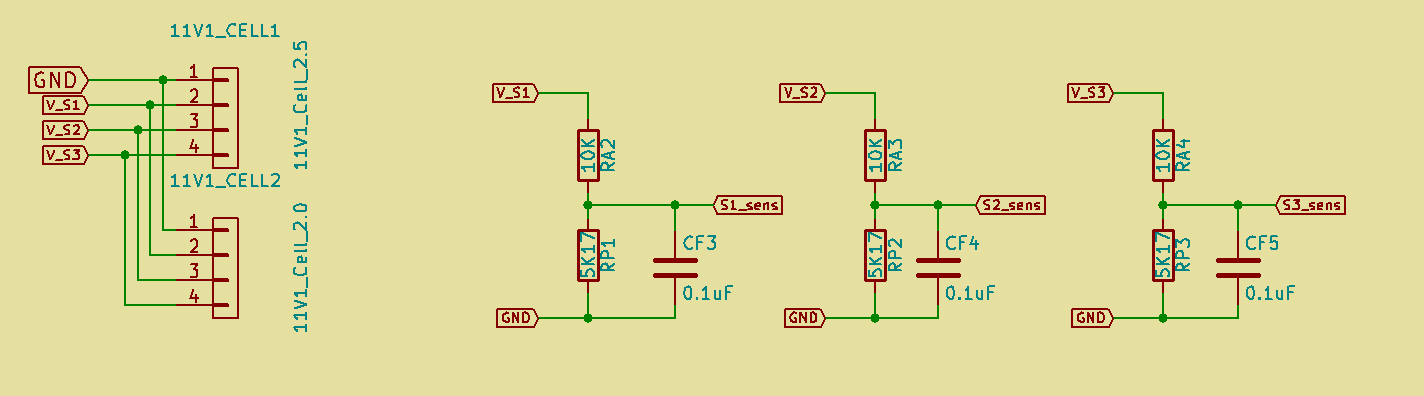
DRONI SAME70Pi / 1.ELECTRONICS / PCB BOTTOM LiPo CELL MEASURE
03/21/2018 at 00:16 • 0 commentsTo have the possibility to measure the remaining power of the LiPo it is more accurate to measure the voltage of each cell in parallel with the current.
A simple algo regarding the typical V=f(I) of the LiPo will give an idea about the remaining charge.With this circuit we measure the voltage of the three cells.
I need only to plug the cells connector to the PCB BOTTOM to have the info.
I also added a second connector in case you I want to charge the battery while it is connected to the PCB BOTTOM.The voltage of the cells, the current and voltage provided by the LiPo are sent to the PCB TOP using a 6pins connector.
-
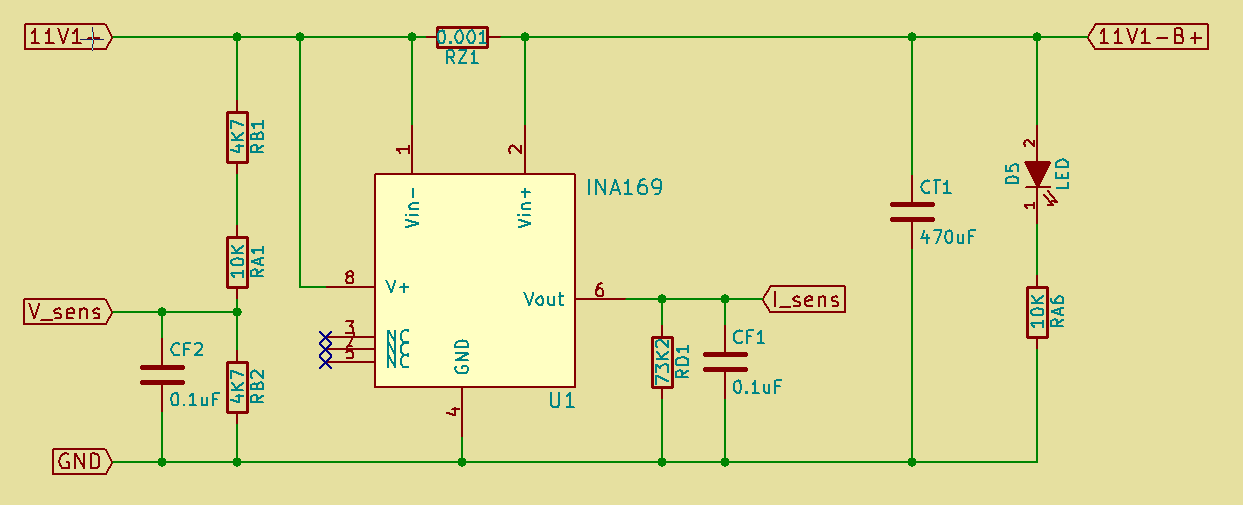
DRONI SAME70Pi / 1.ELECTRONICS / PCB BOTTOM CURRENT SENS
03/21/2018 at 00:06 • 0 commentsTo measure the current provided by the LiPo we use the INA169 chip with a 0.001 resistor.
We measure also the voltage.
It is configured to select a range between 0-50A. -
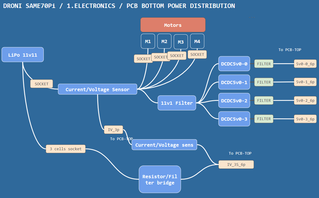
DRONI SAME70Pi / 1.ELECTRONICS / PCB BOTTOM POWER DISTRIBUTION
03/21/2018 at 00:04 • 0 commentsThe 5V0 voltage provided by the PCB BOTTOM is behind a filter.
The PCB BOTTOM provides 4x5V0.
There are multiple DC converters due to current limitation for each.The PCB bottom provides the voltage to the motors.
It has a current sensors using a 0.001 ohm resistor with INA aplifier.
It provides the voltage of the 3cells of the LiPo to the PCB TOP.
-
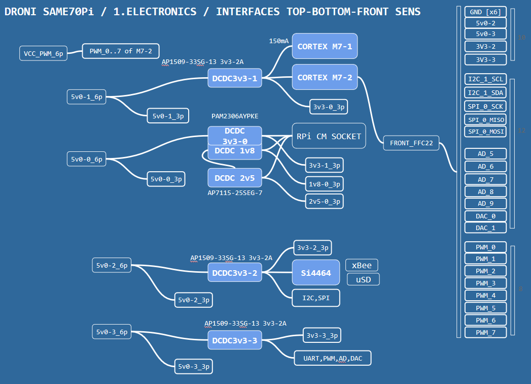
DRONI SAME70Pi / 1.ELECTRONICS / PCB-TOP POWER USE
03/20/2018 at 23:50 • 0 commentsHere is the interfaces regarding the power needs/uses and the front sens connector.
It describes the connector used in the TOP PCB.There are mainly three types of connectors:
- JST/Molex 1.25mm like 6p
- JST/Molex 1.25 like 3p
- PFC connectors for the RPI CAM sockets and for the front sens panel
The power of the RPi CAMs are not represented, they are directly distributed by the compute module.The SAME70-M1/M2 are powered with the same converter.
Each signal connector (UART, DAC,..etc) has GND/3V3/Signals, the 3V3 comes from a dedicated converter.
The communication modules are also powered by a dedicated converter. -
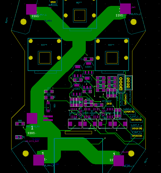
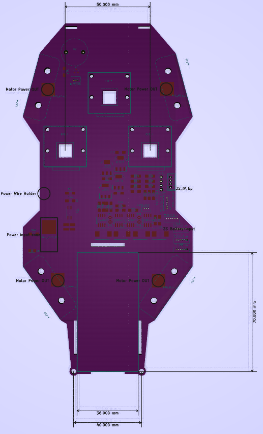
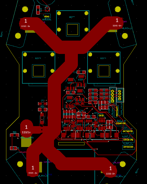
DRONI SAME70Pi / 1.ELECTRONICS / PCB BOTTOM DESIGN (Update)
03/20/2018 at 11:40 • 0 commentsHere is the PCB BOTTOM that handles the power distribution.
It has a current sensor, a buzzer, a bunch of DC converters and connectors, and the fixations of the Pi CAM!
Th
I sent them to manufacturing with the TOP PCB, hope getting them before this weekend to start the assembly :)
I distributed the +11V1 directly.
Located in the top layer of the Cu.The 0V of the LiPo is also distributed directly to avoid short cuts of a faulty isolation.
It is located in the bottom layer of the Cu.
The ESCs and LiPo are connected to the solder pads. -
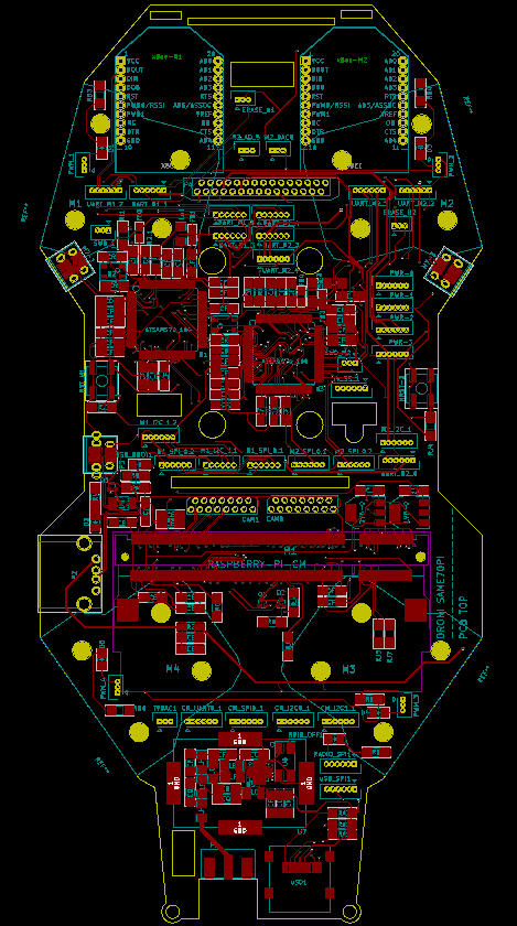
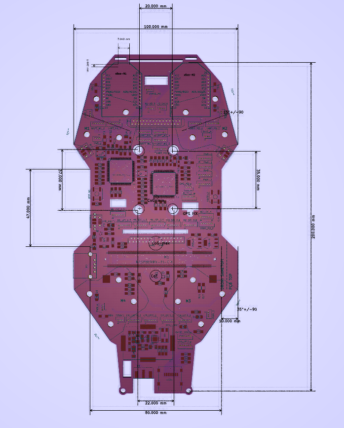
DRONI SAME70Pi / 1.ELECTRONICS / PCB TOP DESIGN (Update)
03/18/2018 at 19:58 • 0 commentsI took into account the dimensions of all the sensors, sockets, arms,...
The initial view is slightly modified.
I moved a little fast on the PCB to have an initial version to make some iterations and verifications in parallel.
Il will give more details about the angles of the arms in another Log.
I just finished the first draw of the PCB TOP that handles the computation and the communication.
The final dimensions will be 100x200mm.
Open Source All-In Drone-Droni SAME70Pi (Kopernik)
Yet another open source platform for drones, but this one is fully integrated and uses the SAME70@300Mhz x2 + a Pi Compute Module
 For almost all the signals the Vcc=3V3.
 The selected mapping of I2C/UART/SPI
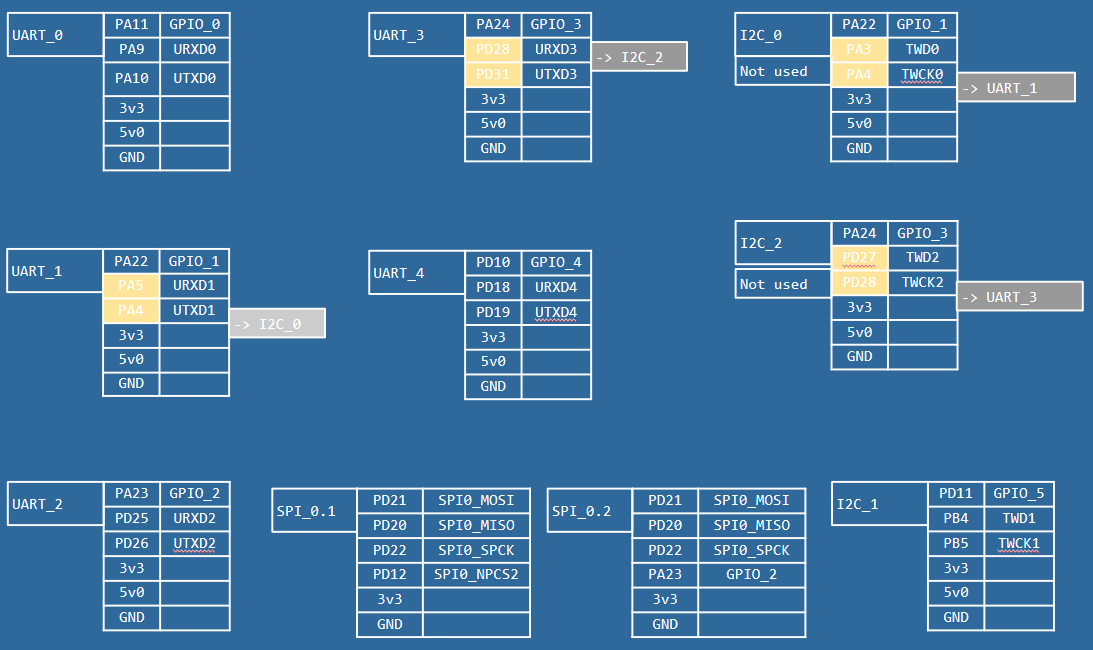
 We keep almost the same architecture.
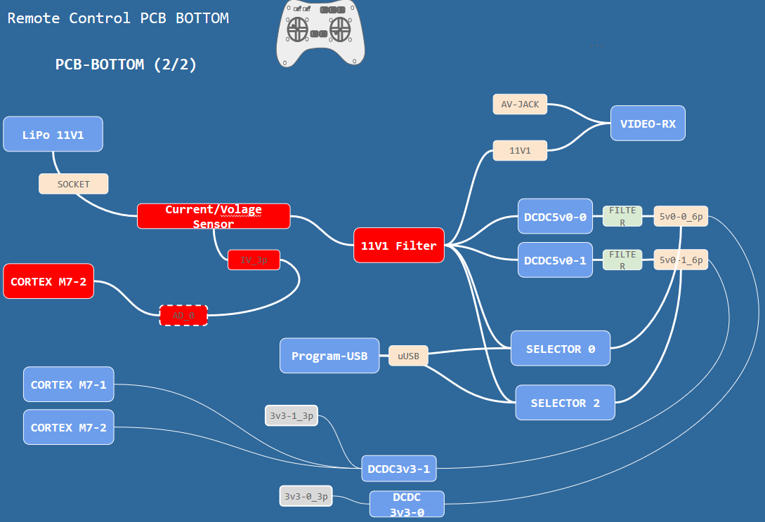
 With this circuit we measure the voltage of the three cells.
 The SAME70-M1/M2 are powered with the same converter.
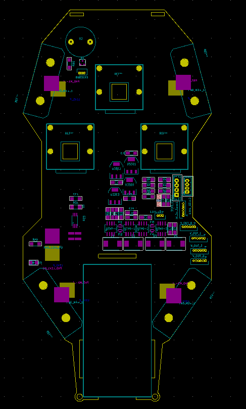
 The 0V of the LiPo is also distributed directly to avoid short cuts of a faulty isolation.