Close
0%
0%

easy-alarm-clock

Improvements for the ubiquitous alarm clock

Public Chat
Similar projects worth following
An alarm clock that gets rid of the annoyances associated with standard alarm clocks.
Some of the annoyances are:
* Only one alarm time for all days of the week. Everyone encounters being woken because you forgot to turn off the alarm for the weekend.
* The alarm time is not visible by default. You have to push some buttons to see it.
* The digits are too bright at night, preventing me to sleep.
* The digits are too small. The designers might have forgotten that people don't wear glasses at night.
* A little dot showing AM/PM. What is what?
* Setting the alarm doesn't turn it on.
* It takes two hands to set it. Was that a safety precaution?
* The buzzer sound is annoying as hell. Who wants to start a day like that?
* Some people complain that the standard alarm clocks are not loud enough.
* In case of power outage, the alarm doesn't sound.
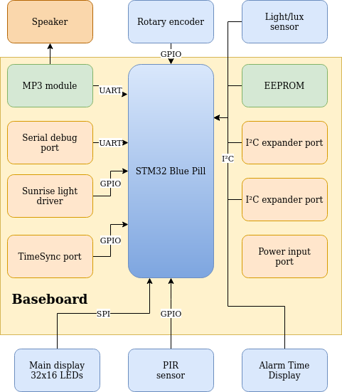
As derived from the block diagram's complexity, it's not easy to build something that is easy to use.

Features

Automatic time synchronization with German atomic clock. No user action required
Automatic switch over to daylight savings time.
Sunrise simulation with rotary encoder to configure the final brightness.  During alarms the light will begin lighting gradually starting 30mins before the scheduled alarm.  The COB-LED array is mounted on the back of the housing to avoid shining the bright light on the sleeping people.  The indirect light of the wall produces a more enjoyable light.
Large LED display : readable without glasses.
Auto brightness for displays and buttons.

  • The brightness of the displays and LEDs is adjusted according the the ambient light.
  • When dark, the displays and LEDs will turn off after 15s so that you can sleep in complete darkness.
  • Movement detection : display will turn on again when movement is detected, which is helpful to find the way to the bathroom and back.

Rubber feet (so it doesn't slide from your closet)
Weekdays setting : the alarm can be configured for separate days of the week. So there's no longer a need to turn your alarm off on Fridays to avoid being woken on Saturday mornings.
✔ Wake-up sound from MP3 (2.5W in a 4ohm speaker) : song selection and volume button controlled by rotary encoder.
One-handed configuration
❌ USB charge port output : It should be discouraged to take a smartphone or tablet to your bedroom.  Give your mind some rest.
❌ Backup supply in case of power outage, powerful enough to sound the alarm. The provisions are there in hardware. Some peripherals can be switched off to save power, but there's no firmware support for it.
USB-B Connector power input.

  • allows for use of decent USB-cables (at least AWG24 for the power pair is required.)
  • Even my grandma will be able to plug this in.  The same can not be said from a USB micro connector, used on the Blaupunkt BT16CLOCK (that's not the only reason to avoid this clock.  Try to turn on the FM radio without using the manual.  Good luck...  The UI is not very intuitive.) 
  • Update (Feb 12 2019) : Micro USB of BT16CLOCK has bad connection.  It's no longer possible to charge the clock. The micro usb connector has been replaced by a standard USB B connector.

Apparently Craig Bonsignore had about the same annoyances with standard clocks, that's why he built his own version.  I'll start off from that design: adding features I miss and scraping off costs where needed.
Modular design in hardware as well as software.  Several components can easily be reused in other projects.

Block diagram

There has been chosen for a modular approach.  The individual modules are small, cheap (<€1/pce) and can be reused in other projects.  
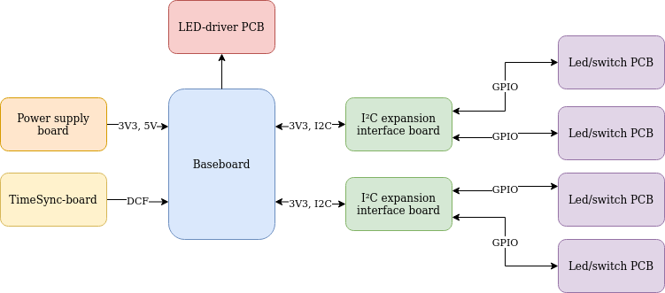
Diagram showing custom designed PCBs for this project

Let's dig a little deeper into the different custom modules:

Electronics ready for mounting
All electronics + Nucleo debugger - power supply board (https://cdn.hackaday.io/images/8356521609096432554.jpg)

Future extensions (unplanned)

  • Wake up module, to be placed under the pillow.  Its vibrations will wake you, even if you're deaf.  It's a nice alternative to a very loud alarm which you're bed partner is not likely to appreciate.
  • Wireless functionality to sync slave clocks around the house.  Bluetooth GATT CTS (Current Time Service) may be of some use here.

Front_panel_Laser_cut.pdf

Laser cutting profile for front panel

Adobe Portable Document Format - 8.23 kB - 05/27/2021 at 18:25

Preview

BRD191226_R1.pdf

Schematic, Assembly Drawing and BoM of the baseboard, revsion R1

Adobe Portable Document Format - 482.45 kB - 08/21/2020 at 08:38

Preview

YX5200-24SSʹÓÃ˵Ã÷ÊéV1.6.zh-CN.en.pdf

Datasheet for the MP3-IC on the DFPlayer Mini module, autotranslated from chinese.

Adobe Portable Document Format - 1.87 MB - 12/27/2019 at 21:30

Preview

  • IO Expansion

    Christoph Tack05/21/2020 at 14:25 0 comments

    There's more IO needed than the BluePill can handle.  The following user IO needs to be controlled :

    • 11 LEDs
    • 11 buttons
    • 1 switch
    • 1 rotary encoder

    So we need an IO expander.  The original setup used a MCP23017 to handle all of this.  It turned out to be not such a good idea.  See below.

    Other options exist:

    1. Use 2 SX1509 boards
    2. 1x SX1509 for button inputs + 1x TLC59711 or TLC5940 for LEDs (expensive)
    3. GPIO for inputs ( 3 rows + 4 columns). 1 TLC59711 for LED output

    16 channel SPI LED driver, non-dimmable : TLC5925 | STP16CPC26 | CAT4016 | MAX6969: 16 outputs, integrated current source, Digikey €1/pce.  Advantage of using these is that charlieplexing is no longer needed.

    • SX1509
      • More than just an I²C IO-expander
        • Keypad scan engine on Rows : IO0 - IO7, Columns :  IO8 - IO15
        • PWM dimming engine for GPIOs
      • Sparkfun
        • pin spacing : 0.6" x 10pin (2x12p DIP socket could be used : Digikey ED3051-5-ND)
        • I²C connection could be made through 1x5pin socket strip
      • power supply : 1V8, 3V3 (not 5V, but IO is 5V tolerant)
      • LED driving capability
        • 15mA sinking/pin
        • 8mA sourcing/pin
    • MCP23017
      • basic I²C IO-expander, not much extra functionality
      • AliExpress module : €0.76
      • Used by Adafruit
      • 25mA push/pull
      • I²C
      • 2 IRQ pins
      • level triggered interrupts, edge triggered interrupts (no distinction between falling and rising edge interrupts)
      • 16bit
      • 3V3, 5V compatible
      • available in SOIC28
      • This device has no internal keypad scanning engine, unlike the SX1509.  So you'll have to drive the rows & columns yourself when using a matrix keypad.  This causes a lot of I²C interrupts and overhead for the MCU.
      • The IO expander also controls the 15 LEDs in this setup using charlieplexing.  A charlieplexing library for the MCP23017 has been developed, loosely based on the Chaplex library
      • Key scanning combined with charlie plexing the LEDs, causes flickering on the LEDs.  Moreover the intensity of the LEDs can't be controlled.
    • MCP23S17
      • SPI version of the MCP23017
    • PCF8574
      • 8bit
    • PCF8575
      • 16bit
      • asymmetrical output driver: 1mA source, 25mA sink

    PCB Design

    The I²C expansion board can control 8LED/switches.  The LED/switch-PCBs have four LED/switches.  If the I²C expander would be incorporated on the LED/switch PCB, effectively 50% of the I²C expander would be wasted.

    All FFC connectors are the same to reduce BoM-cost and lead time.  For the 3V3/I²C-connector, this means that some pins are not really used.

  • LED-switch panel

    Christoph Tack05/21/2020 at 12:43 0 comments

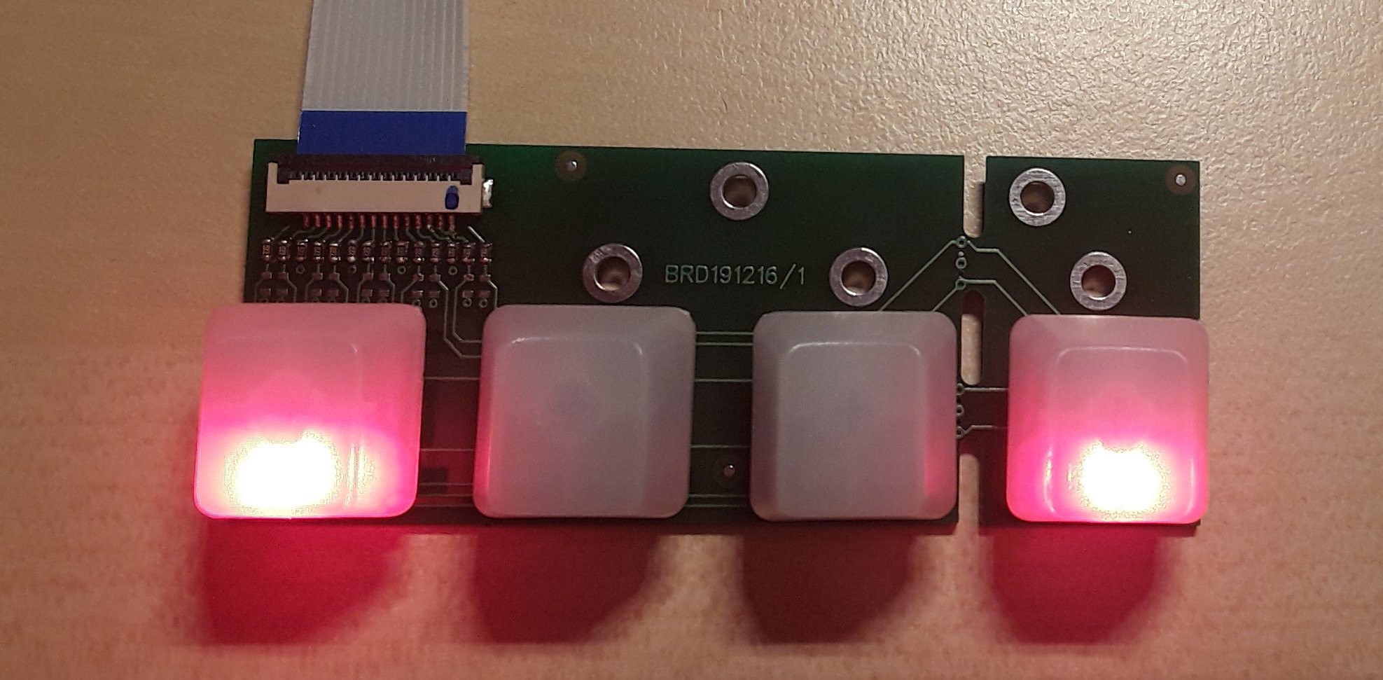
    Yes, it's finally there!

    Design

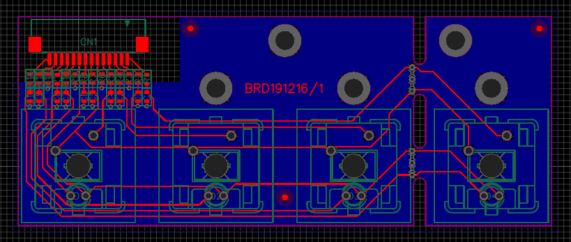
    The PCB has been designed using EasyEDA.  You can find the design there.

    The design needed to be compact, so that multiple of these boards can be connected next to each other while keeping the same spacing between the buttons.  The rightmost button can be snapped off, if needed.

    EMC precautions : resistors and capacitors for filtering, ground plane for signal return.  One third of the FFC pins is GND.  The ground plane on the rightmost switch is poorly connected to the other ground plane.  We'll see what it brings.

    Component choices

    Interconnection

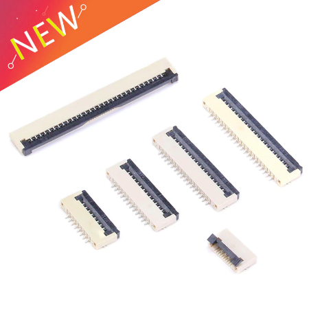
    Requirements for the connectors : cheap, small, easy to solder.  Which brings to to the 1.0mm pitch FFC cable.

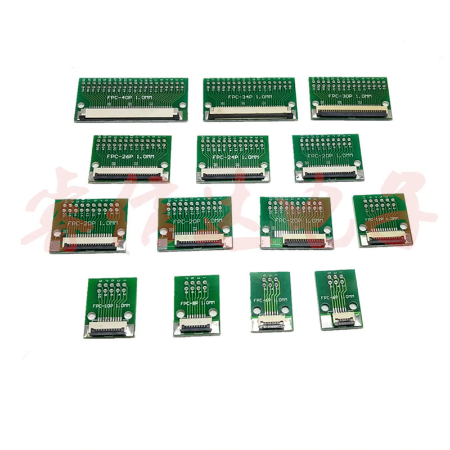
    A little search on AliExpress "ffc 14 pin", brings up a source that can deliver the cables for €0.10/pce.The matching connectors can be had for about €0.05/pce.For debugging, AliExpress also provides breakout boards at €0.91/pce.
    Remark that the breakout comes in dual row, so it's not breadboard friendly.

    Buttons

    Requirements : big buttons, should be able to handle lots of operations, visual feedback (through LED).  The selection can be found on a separate page.

    Bonus facts

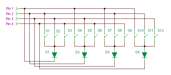
    The I²C-expander uses matrix keyboard scanning.  This requires 8 IO lines for 15 switches.  If not enough IO lines had been available, there would be an alternative approach as described by Mosaic Industries:

    This technique would require only 5 IO lines for 15 switches (max. 20 switches).  The downside is that 5 diodes need to be added.  This probably won't work with an SX1509 or similar which has a built in keypad scanning engine.

  • Baseboard

    Christoph Tack05/21/2020 at 12:35 0 comments

    Diagram

    The diagram above gives an overview of the baseboard.  The yellow background represents the baseboard and the functionality present onto it.  The other modules (speaker, rotary encoder, sensors, displays) are external modules.

    Old data:
    Rev.0: IO Panel : LCDs, switches, IO expansion, LED array, light sensor all integrated on one PCB

    Verifying interfacing to peripherals

    • ☑ MP3 module
    • ☑ Serial debug port
    • ☑ Main display 32x16 LEDs
    • ☑ 2x I²C expander port : Unfortunately, both connectors should have been 14pins FFC instead of 10pins FFC now.  I solved it by cutting off three tracks of the FFC-connector.  It would have been a cleaner workaround to replace the FFC-connectors on the I²C-expansion boards by 10pin types.  But then I would also have to buy 10pin FFC-cables.
    • ☑ EEPROM
    • ☑ Rotary encoder
    • ☑ Time sync port
    • ☑ PIR sensor
    • ☑ Alarm time display
    • ☑ Light sensor
    • ☑ Sunrise simulation

  • Firmware

    Christoph Tack01/26/2019 at 21:10 0 comments

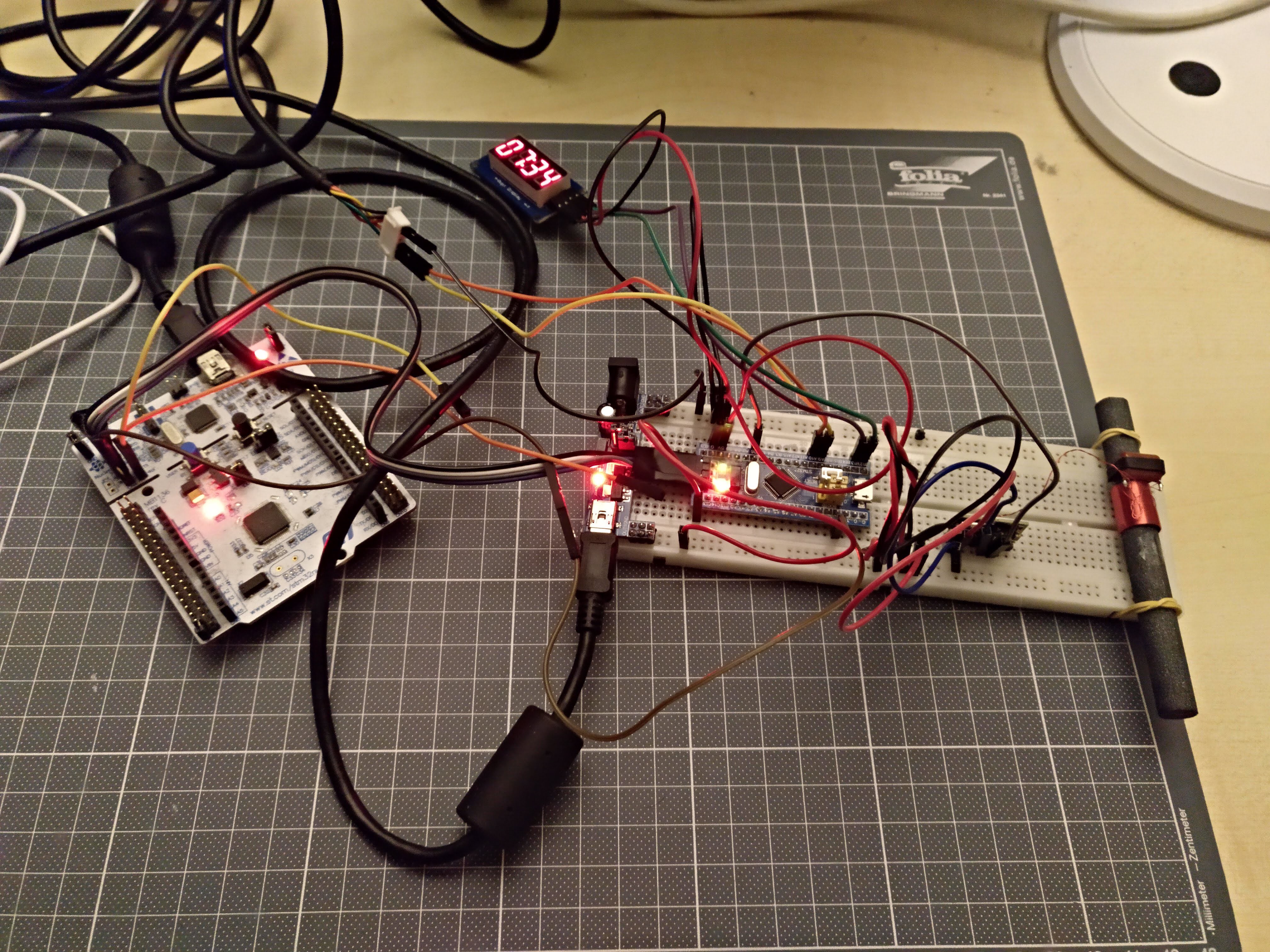
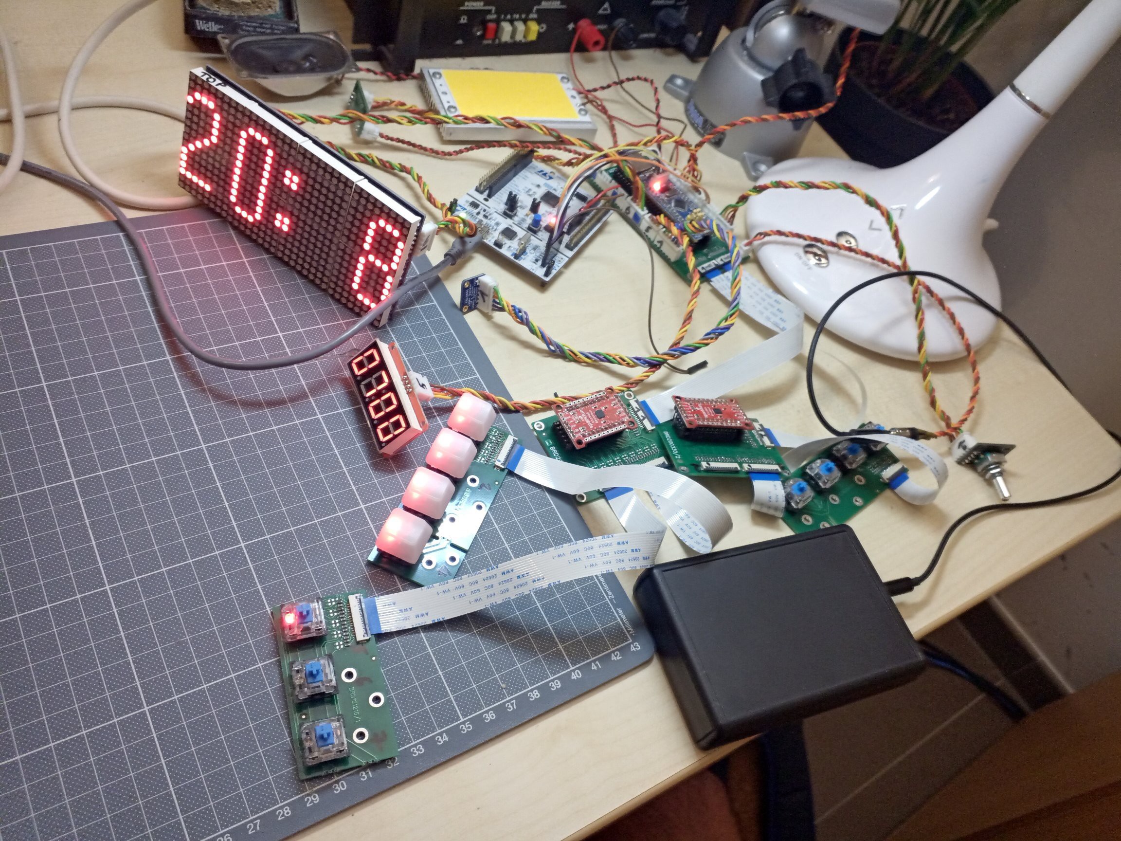
    Test hardware

    Big mess o' wires : don't repeat my mistake, instead put the antenna and the DCF receiver on a separate breadboard.

    This setup has the BluePill on the breadboard, connected to a Nucleo debugger (white PCB on the left).  The 7segment module on top connects to two GPIOs of the BluePill.  The BluePill receives its DCF-pulse info from a DCF-receiver on the breadboard.  That DCF-receiver is connected to a DCF-antenna, attached with rubber bands to the breadboard.

    DCF-signals are very weak.  Making breadboard connections with relatively long wires as done here, makes the BluePill a fairly good RF noise radiator.  So with the setup as shown here, it's nearly impossible to get a correct DCF-reading.  The picture was actually taken around 9PM.  The DCF-library makes a best guess of the data it receives.  There's no reliability threshold, so wrong data might be shown in the event of a useless signal.  Most of the times, even with a bad signal, the clock recovers and finds the correct time.

    I faced the same problems with the BluePill when trying to receive FM-RDS.  Using a Nucleo, results were a little bit better, even with the same mess of wires.

    Code can be found on Github.

    DCF signal quality for the same setup the next day, on Sunday, about the same time of day was much better.  No easy explanation about what caused such an interference on Saturday night.


    Parameter setup

    This design has quite a lot of parameters that can be set.  It's challenging to find a way to set these all up easily using only a 32x16 display.  The display can only show 10 characters at a time.

    Menu input would be limited to using a rotary encoder or a few switches.

    I have tried a few menu libraries for Arduino : Arduino Menu System, Arduino_LCD_Menu and ArduinoMenu.  They all suffer from the same problems:

    • Requiring a lot of key presses for setting up parameters
    • Difficulty of displaying the menu hierarchy in a way that is simple to grasp.  E.g.  setting the weekdays for the alarms are four levels deep in the menu.  Without a menu overview, it will be hard to keep track of what you're setting up.

    Let's take the Google clock app for Android as a reference.  This app allows to setup more or less the same parameters as listed below.  Using the app, an alarm can be setup in less than 30s.  This would be nearly impossible to do with a 32x16 LED array and four buttons.

    Solution

    Parameter setup will be done using physical switches.  A combination of DIP switches and rotary switches will be used. 

    Advantages:

    • Each parameter can be set without having to browse through the other parameters, speeding up the parameter setup process
    • Parameter status is indicated by the physical state of the switch.  This doesn't require power and doesn't cause undesirable light output at night.
    • Depending on the target audience, the switch functionality can be implemented using DIP-switches and rotary switches or with panel mount toggle switches and rotary switches that allow for older people to control the device.

    Disadvantages:

    • Adds cost, because it requires a lot of extra hardware
    • No other means for setup of parameters (e.g. through bluetooth) because the switches would no longer reflect the current settings.  A way to circumvent this, would be to replace the rotary switches by rotary encoders & 7segment displays and replacing the dip switches by momentary switches and LEDs.

    The input panel will be implemented on a separate PCB, allow for upgrade, changes in a future stage.

    Menu structure

    • Alarm 1 (Alarm 2 has the same menu structure).  The menu item is dynamic.  An icon shows if the alarm is enabled or not, followed by the alarm time
      • Activation
        • On
        • Off
      • Time
        • HH:mm
          • minutes can only be set in 5min. steps.  It allows to set up time faster.  Nobody wants to get up at...
    Read more »

  • Housing

    Christoph Tack01/20/2019 at 11:50 0 comments

    Main housing

    There are multiple options for creating a housing for an electronics project.  I don't have interest in learning a decent program like Fusion360 for creating laser cut drawings.  The one-time cost of a standard box doesn't weigh up against all the hours invested in learning a new tool.  So I'll settle for a standard housing.  The OKW P/4.9-AL (drawing) might be a good choice:

    • cheap (around €10)
    • dimensions are ok (215 x 130 x 77mm).  Wide enough, so that it doesn't easily fall over.
    • front panel can be replaced by a PCB, or laser cut panel.
      • The front panel is a thin aluminium sheet.  I milled the needed slots in it using a Dremel multifunctional rotary tool, but the result isn't very clean.
      • The original front panel is too flexible now with all the cutouts.

    To be fair, it would have been better if the housing was 10mm higher and 10mm narrower.  That would have allowed for a nicer placement of the alarm LCD.

    Material

    Because of the sunrise simulation, the housing, or a least a major part of it must be translucent or transparent.  Translucent materials are preferred as the diffusion of the light will make the housing light up as a whole.  It's an option to use transparent materials for the housing and stick a translucent film onto it.

    • Acrylic : can be laser cut

    Box design

    Online file generators for laser cutting

    Manufacturers

    Antenna enclosure

    There's a chance that the electronics of the generate too much EM-noise, so that the antenna and receiver need to be placed in a separate housing.

    A suitable housing is the Hammond 1593NBK (Farnell €2.75).

    If you want to build a really cheap enclosure for your antenna with hot glue and some scrap piping, have a look here.

    Further reading

    Adafruit : Laser cut enclosure design

    Front panel

    This still leaves options for the front panel.  An aluminium front panel is nice, but expensive (Front Panel Designer).  An alternative would be to create the front panel instead as a (non functional) PCB.

    Open source CAM tools

    https://github.com/geobruce/FabLab/blob/master/CAM-tools-CNC.md

  • Power supply

    Christoph Tack06/28/2018 at 11:41 0 comments

    Requirements

    If no sunrise LED is needed, then the electronics could be powered from a 5W USB wall charger.  The sunrise LED will probably need about an extra 10W.

    Cable

    Not all USB cables are made equal.  I read about it in the past and I ran into the same problem.  The cable I originally used, had an AWG28 for power.  I lost more than 1V over it when the light of the circuit was on.  Only 3.13V remained at the 5V signal (the power supply also has internal resistance).  This resulted in unstable behavior with the MP3 player.
    Switching it with a AWG24 cable, which had a much lower internal resistance fixed my problem.  USB Cables of AWG22 and AWG20 also exist, but these tend to be longer or much more expensive.

    Backup

    The common solution is to use a goldcap as back up power supply.  The limitations of goldcaps are:

    • limited energy storage capacity
    • high internal resistance
    • voltage decreases linearly with respect to the current being drawn.

    All of this makes that in case of power outage the goldcap can't be used to sound the alarm to wake the user.

    An alternative approach will be used here.  A cheap alkaline AA-cell will power a MCP1640 boost converter that will step up the voltage to the required 3V3.  As long as the normal power is supplied, the MCP1640 can be disconnected from the AA-cell.

    Filtering

    DCF-communication is susceptible to noise.  Proper filtering is needed to reduce the risk of bad signal reception.

    Connector

    USB-C connector

    USB-C allows for a maximum power transfer of 20V/5A.  This would be more than enough for this project.

    The advantage of using a USB-C connector would be that a power adapter with USB-C could be used.  These will probably be quite standard in the near future.  At the time of writing (2018) these are still expensive.

    There are more drawbacks: to get the 20V/5A, the device delivering the power and the device sinking the power must communicate with each other using BMC-coding.  This is implemented in the Richtek RT1715 and the TI TUSB32x family.  These devices are still rather expensive.  The SMD packages are small and hard to solder by hand.

    Using this connector would be a typical case of over engineering.  There's no real advantage is using USB-C only for powering a device.  The exception could be for powering an electric razor.  You could use your phone charger to power it.  It saves you one power adapter in your luggage.

    DC jack

    Cheap, readily available, reliable...  The drawback is that there's no guarantee about the voltage level and polarity.  The user can connect whatever (s)he likes.  It's up to the powered device to cope with this.

  • Sunrise LED

    Christoph Tack06/24/2018 at 16:12 0 comments

    Background

    A gradually brighter light can mimic the sun rise.  It will allow for gentle wake-up in the morning.  

    Experience with the Philips HF3463 showed me that you shouldn't count on it to get up on time.  I sometimes find myself waking up by the alarm sound and facing the alarm clock in full brightness.  When you're sleeping on your side and the light is behind you, it won't wake you either.

    LED driver modules

    The plan is to power the clock from a 5V USB power adapter.  The LEDs require about 12V/500mA.  So we need a boosting LED module, not a buck module.

    If we decide to make the module ourselves, we need to select an IC:

    • easy to solder : SOT23 is ok, QFN isn't
    • over voltage protection (when LED is not connected or broken).  Proper solutions directly sense the output voltage using an extra pin.  This brings the minimum number of pins for the IC to 6 : gnd, vin, vout, sw, fb, en.
    • VIN min < 5V
    • VIN max > 5V
    • VOUT min > 12V
    • IOUT > 1A (we need 500mA).  Don't confuse this with the switch current.  The input current of a boost converter is essentially the inductor current.  When the boost converter switch is conducting, the input current is equal to the switch current.  If we need 6W at the output, we need at least 8W at the input.  The switch current should be at least 2A to be safe.
    • low power.  Remark that the output LEDs continue to draw current when the LED module is in shutdown.  External circuitry is needed to fully shut down the LED module.
    • dimming capability (analog & digital dimming are explained in the MP3202 datasheet)

    Digikey selection (for 1A switch current): RT4533GJ6 and MP3202 (pin compatible), TP61165 (not pin compatible)

    In the hindsight, the LM3410 would have been a better option, because it allows for larger drive currents.

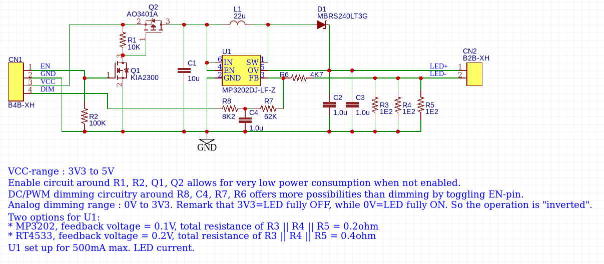
    Revision 1.0

    Details about this circuit can be found on EasyEDA.

    The circuitry above has some issues:

    • Thick wires must be used for VCC & GND because they have to carry up 1.1A.  These wires will probably too thick to fit in the JST-XH.  For debug, I soldered thicker wires on bottom side.
    • The current is set for 500mA, but only about 400mA is being drawn.  The feedback voltage never reached 200mV.  The 0.4ohm sense resistor combination had to be replaced by a 0.5ohm (2x 1ohm) resistor combination.
    • Value of the resistors for analog dimming are too big.  As the PCB is quite small, they pick up some noise.  Making them a factor of 10 smaller improves it a lot.

    The RT4533 announces itself as boost converter for 10W LEDs 10 WLEDs.  It's important where you put the space.  Richtek means you can drive 10 white LEDs.  It's easy to misread it as : "RT4533 can drive 10W LEDs".

    It may well be possible to drive LEDs, but not at 10W.  Let me explain:

    1. The maximum input voltage for the RT4533 is 5.5V
    2. The maximum switch current is 1.2A.  For a boost regulator, this is also the maximum current through the inductor.  The current through the inductor is essentially the input current to the circuit.
    3. So maximum input power is 5.5 * 1.2 = 6.6W
    4. Let's be optimistic and assume the output power is 80% of the input power : 5.3W, which is far from the advertized 10W.
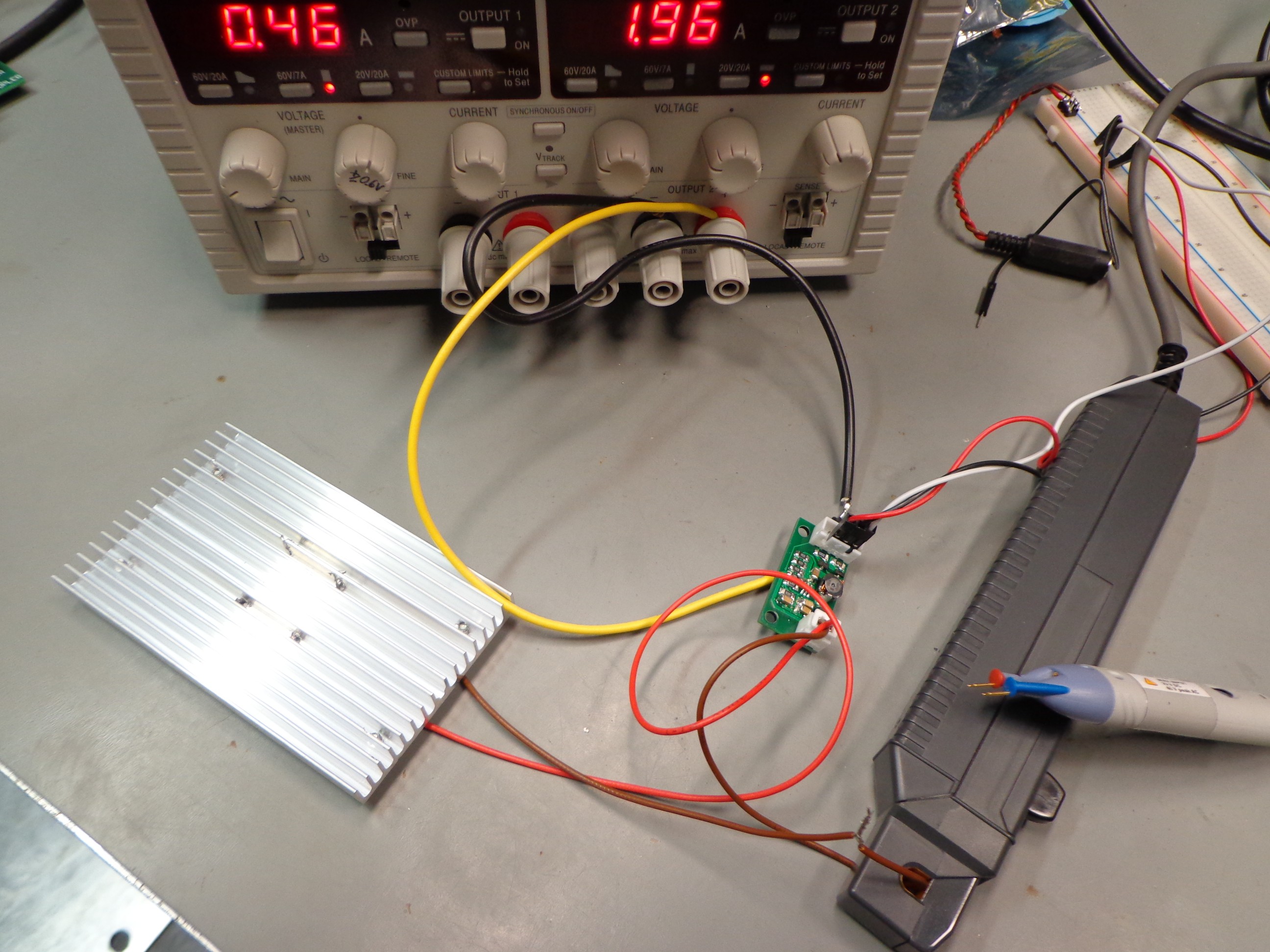
    Measurement setup: dual power supply (set to max. 1.96A. Voltage output was disabled when picture was taken), R&S Current probe, R&S differential voltage probe.

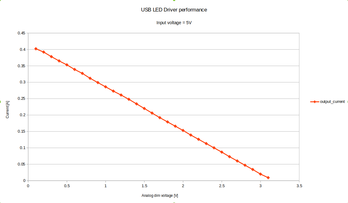
    Measurement results

    The output current drops linearly with the control voltage, as expected.

    Efficiency is around 80%, as shown on the RT4533 datasheet.

    The module already saw a second use as a replacement driver for lighting the christmas tree. The original driver was specified for 32V/100mA. Setting the two sense resistors to 3.9ohm and you're done.  Power draw on the 5V power supply was about 800mA.

    Dimming the light using PWM

    Earlier experiments with dimming LEDs showed me that 8bits is not enough to generate smooth transitions. ...

    Read more »

  • Inspirational clocks

    Christoph Tack05/10/2018 at 20:30 0 comments

    LED animations are nice, but they shouldn't stand in the way of functionality.  The DOTKLOK has very long time transition animations.  This will get annoying real soon.

    Some of the clocks show the time up to second resolution.  For a bed side alarm clock, I don't see a point in doing that.  Besides, how accurate is the clock anyway?  If the clock is not regularly synced to some time source, the shown seconds will be incorrect.  Second resolution is useful in timers (for cooking etc.), but an alarm clock is not a timer.

    O-Led Morphing clock

    Nice animations

    link

    Harifun's Morphing Digital Clock

    Nice animation, (too) big LED array, too bright, blue color will keep you awake

    Harifun's Morphing Digital Clock

    Craig Bonsignore's Open Clock Project

    Nice clock, but without a manual, you can't properly operate it.  Sometimes digits are green and sometimes red.

    Craig Bonsignore's Open Clock Project, also on Hackaday.io

    Xronos Clock

    Xronos Clock
    The idea of the arcade buttons is good, but the menu navigation is quite unusual.  The black button cycles through the menu items of the top hierarchy level.  The red button is used to go from top hierarchy to the level second level.  Then it cycles through the menu items of that second level.  The white button finally is used to change user settings.  As there are only three buttons, you can only cycle in one direction through the items.  For setting the year or the minutes of the hour, that's quite annoying.  A fourth button would have made menu navigation a lot more intuitive: up, down, select & back.

    See how long it takes and how many key presses are needed to set it all up?

    Nice housing

    Matrix Clock

    Nice animations

    Matrix Clock (technical data can be downloaded here)

    DOTKLOK

    Nice animations

    DOTKLOK

    Alpha Clock Five

    • Simple housing
    • Expensive LED display.
    • Acrylic housing (laser cut)

    Alpha Clock Five

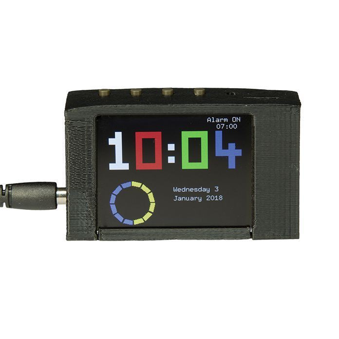
    3-Way Display Alarm with 2.2" TFT

    • Has a brightness setting for day, night and allows setting brightness level for day/night transition.
    • It's personal taste, but :
      • I dislike the use of a different color for each digit.
      • Why design & 3D-print a RECTANGULAR housing?  Choose a COTS-housing, design your electronics to fit that housing, make cutouts in the housing where needed.

View all 8 project logs

Enjoy this project?

Share

Discussions

Christoph Tack wrote 06/05/2021 at 08:48 point

Hi Christoph,

Your clock looks great!  The Nextion display was a good idea as an HMI.  It reduced the complexity for the firmware in as much that you were able to use a Arduino Micro to control it.  It's great to see how much features can be set up on the display.  Personally, I would limit the number of settings or hide some of them in an "advanced" menu.  Many users won't need them, but that's personal taste.

The bulk of the development time on my project was spent on developing the UI.  If I had to do it again, I would use an ESP32, clock sync through NTP and parameter setup through web pages with the ESP32 as webserver.  This limits hardware costs and development time, but the user needs a smartphone, wifi and knowledge of how to access a webpage.  This easy-alarm-clock can be setup by a 6 year old kid.  When taking the ESP32 approach, the intended audience would be different.

  Are you sure? yes | no

Chris B wrote 06/04/2021 at 20:29 point

Hi Christoph, 
my name is Christoph and I am annoyed by all the ubiquitous alarm clocks that are so far from fulfilling everyone's needs (Or may I just have special requirements to them? :D ) - so I started building my own. Reading your wanted special features for the clock it seems like we have more in common than just our first name. :D
I like your approach - seems similar to my second-last "ultimate clock"-project. You can have a look at my last one here: https://hackaday.io/project/164713-ultimate-alarm-clock
In the end I decided to use a touch-display to reduce the number of HMI and display interfaces as this made the project very (= too) complex. If I had time for another "ultimate clock" version I probably would use a touchscreen on top of a RasPi as a base as there are already a power-USB connector, WiFi for the current time (and maybe even alarm songs) and an audio output available. 
Maybe my project site could inspire you a bit? I wish you good luck and success for your project!

  Are you sure? yes | no

Similar Projects

Does this project spark your interest?

Become a member to follow this project and never miss any updates