There's more IO needed than the BluePill can handle. The following user IO needs to be controlled :
11 LEDs
11 buttons
1 switch
1 rotary encoder
So we need an IO expander. The original setup used a MCP23017 to handle all of this. It turned out to be not such a good idea. See below.
Other options exist:
Use 2 SX1509 boards
1x SX1509 for button inputs + 1x TLC59711 or TLC5940 for LEDs (expensive)
GPIO for inputs ( 3 rows + 4 columns). 1 TLC59711 for LED output
16 channel SPI LED driver, non-dimmable : TLC5925 | STP16CPC26 | CAT4016 | MAX6969: 16 outputs, integrated current source, Digikey €1/pce. Advantage of using these is that charlieplexing is no longer needed.
level triggered interrupts, edge triggered interrupts (no distinction between falling and rising edge interrupts)
16bit
3V3, 5V compatible
available in SOIC28
This device has no internal keypad scanning engine, unlike the SX1509. So you'll have to drive the rows & columns yourself when using a matrix keypad. This causes a lot of I²C interrupts and overhead for the MCU.
The IO expander also controls the 15 LEDs in this setup using charlieplexing. A charlieplexing library for the MCP23017 has been
developed, loosely based on the Chaplex library.
Key scanning combined with charlie plexing the LEDs, causes flickering on the LEDs. Moreover the intensity of the LEDs can't be controlled.
MCP23S17
SPI version of the MCP23017
PCF8574
8bit
PCF8575
16bit
asymmetrical output driver: 1mA source, 25mA sink
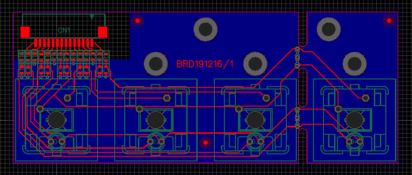
PCB Design
The I²C expansion board can control 8LED/switches. The LED/switch-PCBs have four LED/switches. If the I²C expander would be incorporated on the LED/switch PCB, effectively 50% of the I²C expander would be wasted.
All FFC connectors are the same to reduce BoM-cost and lead time. For the 3V3/I²C-connector, this means that some pins are not really used.
The PCB has been designed using EasyEDA. You can find the design there.
The design needed to be compact, so that multiple of these boards can be connected next to each other while keeping the same spacing between the buttons. The rightmost button can be snapped off, if needed.
EMC precautions : resistors and capacitors for filtering, ground plane for signal return. One third of the FFC pins is GND. The ground plane on the rightmost switch is poorly connected to the other ground plane. We'll see what it brings.
Component choices
Interconnection
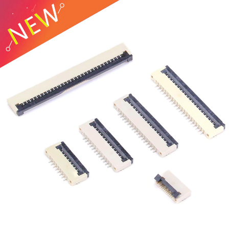
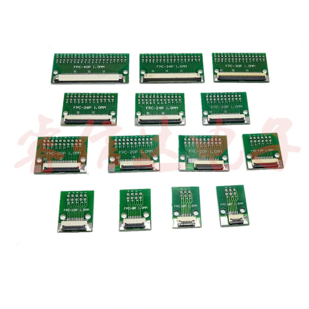
Requirements for the connectors : cheap, small, easy to solder. Which brings to to the 1.0mm pitch FFC cable.
The matching connectors can be had for about €0.05/pce.
For debugging, AliExpress also provides breakout boards at €0.91/pce. Remark that the breakout comes in dual row, so it's not breadboard friendly.
Buttons
Requirements : big buttons, should be able to handle lots of operations, visual feedback (through LED). The selection can be found on a separate page.
Bonus facts
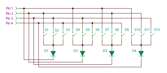
The I²C-expander uses matrix keyboard scanning. This requires 8 IO lines for 15 switches. If not enough IO lines had been available, there would be an alternative approach as described by Mosaic Industries:
This technique would require only 5 IO lines for 15 switches (max. 20 switches). The downside is that 5 diodes need to be added. This probably won't work with an SX1509 or similar which has a built in keypad scanning engine.
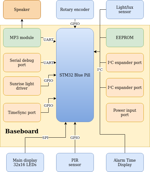
The diagram above gives an overview of the baseboard. The yellow background represents the baseboard and the functionality present onto it. The other modules (speaker, rotary encoder, sensors, displays) are external modules.
Old data: Rev.0: IO Panel : LCDs, switches, IO expansion, LED array, light sensor all integrated on one PCB
Verifying interfacing to peripherals
☑ MP3 module
☑ Serial debug port
☑ Main display 32x16 LEDs
☑ 2x I²C expander port : Unfortunately, both connectors should have been 14pins FFC instead of 10pins FFC now. I solved it by cutting off three tracks of the FFC-connector. It would have been a cleaner workaround to replace the FFC-connectors on the I²C-expansion boards by 10pin types. But then I would also have to buy 10pin FFC-cables.
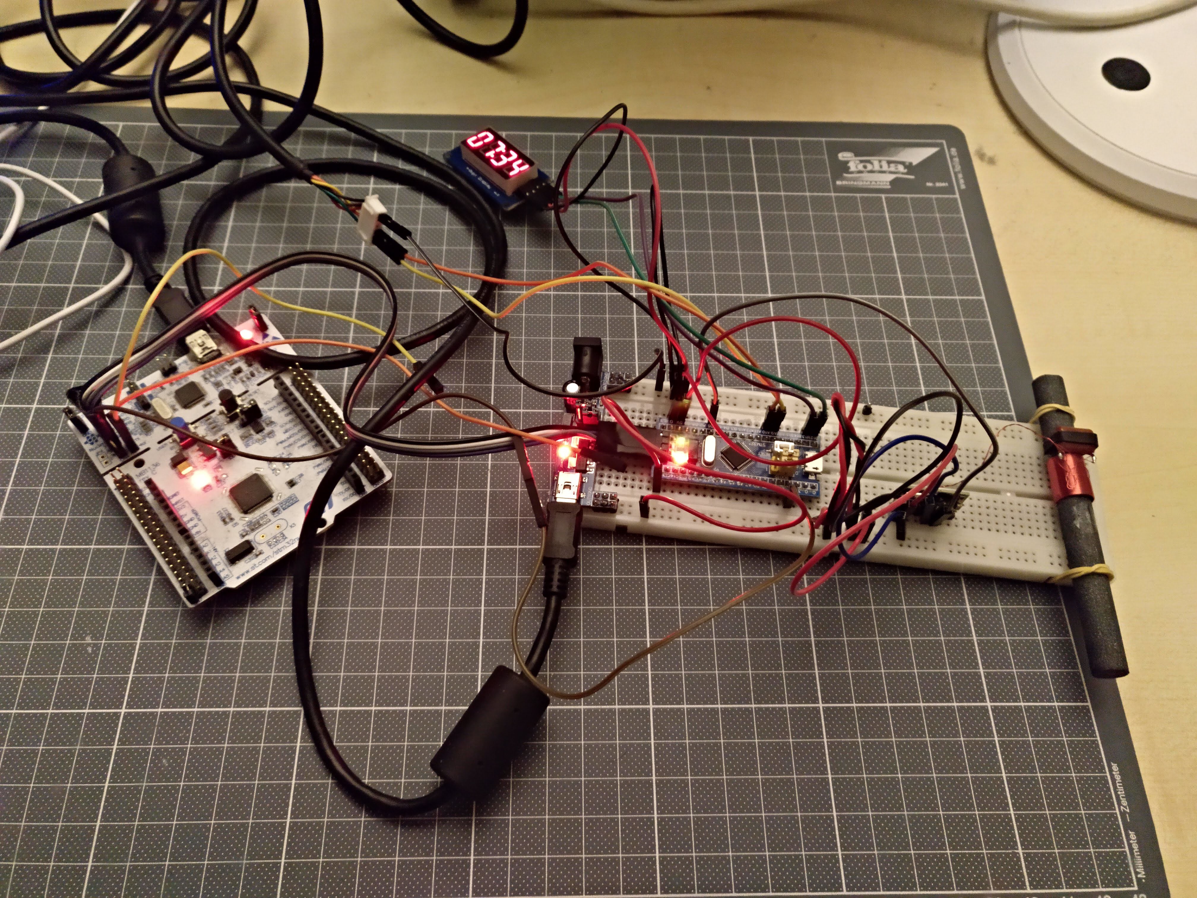
Big mess o' wires : don't repeat my mistake, instead put the antenna and the DCF receiver on a separate breadboard.
This setup has the BluePill on the breadboard, connected to a Nucleo debugger (white PCB on the left). The 7segment module on top connects to two GPIOs of the BluePill. The BluePill receives its DCF-pulse info from a DCF-receiver on the breadboard. That DCF-receiver is connected to a DCF-antenna, attached with rubber bands to the breadboard.
DCF-signals are very weak. Making breadboard connections with relatively long wires as done here, makes the BluePill a fairly good RF noise radiator. So with the setup as shown here, it's nearly impossible to get a correct DCF-reading. The picture was actually taken around 9PM. The DCF-library makes a best guess of the data it receives. There's no reliability threshold, so wrong data might be shown in the event of a useless signal. Most of the times, even with a bad signal, the clock recovers and finds the correct time.
I faced the same problems with the BluePill when trying to receive FM-RDS. Using a Nucleo, results were a little bit better, even with the same mess of wires.
DCF signal quality for the same setup the next day, on Sunday, about the same time of day was much better. No easy explanation about what caused such an interference on Saturday night.
Parameter setup
This design has quite a lot of parameters that can be set. It's challenging to find a way to set these all up easily using only a 32x16 display. The display can only show 10 characters at a time.
Menu input would be limited to using a rotary encoder or a few switches.
Requiring a lot of key presses for setting up parameters
Difficulty of displaying the menu hierarchy in a way that is simple to grasp. E.g. setting the weekdays for the alarms are four levels deep in the menu. Without a menu overview, it will be hard to keep track of what you're setting up.
Let's take the Google clock app for Android as a reference. This app allows to setup more or less the same parameters as listed below. Using the app, an alarm can be setup in less than 30s. This would be nearly impossible to do with a 32x16 LED array and four buttons.
Solution
Parameter setup will be done using physical switches. A combination of DIP switches and rotary switches will be used.
Advantages:
Each parameter can be set without having to browse through the other parameters, speeding up the parameter setup process
Parameter status is indicated by the physical state of the switch. This doesn't require power and doesn't cause undesirable light output at night.
Depending on the target audience, the switch functionality can be implemented using DIP-switches and rotary switches or with panel mount toggle switches and rotary switches that allow for older people to control the device.
Disadvantages:
Adds cost, because it requires a lot of extra hardware
No other means for setup of parameters (e.g. through bluetooth) because the switches would no longer reflect the current settings. A way to circumvent this, would be to replace the rotary switches by rotary encoders & 7segment displays and replacing the dip switches by momentary switches and LEDs.
The input panel will be implemented on a separate PCB, allow for upgrade, changes in a future stage.
Menu structure
Alarm 1 (Alarm 2 has the same menu structure). The menu item is dynamic. An icon shows if the alarm is enabled or not, followed by the alarm time
Activation
On
Off
Time
HH:mm
minutes can only be set in 5min. steps. It allows to set up time faster. Nobody wants to get up at three minutes past seven anyway.
Repeat
Once
Weekly
M, T, W, T, F, S, S
Daily
Type
SND + LIGHT
SOUND ONLY
LIGHT ONLY
Sound (only when sound is enabled)
Bamboo
Jazz
Guitar
Piano
Volume (only when sound is enabled)
0 to 100>#/li###
Light (only when light is enabled)
0 to 100>#/li###
Navigation
The Nokia 3310 features an elegant way of navigating the menu. Three buttons are involved:
A two-way switch for scrolling through the menu.
A "select" button to accept a certain choice
A "back" button to cancel.
Time keeping
STM32 RTC
The STM32F103 on the BluePill has a built-in RTC. Luckily, there's already a library for it, so it should be a breeze to implement it. Or not...
Using code as is
To check the accuracy of the RTC, I wrote an application that can receive UTC epoch time from the serial port. The application also reports the difference with a newly sent UTC epoch time. Sending UTC time to the BluePill as follows:
echo -ne $(date +%s) > /dev/ttyACM0
Serial output from the BluePill:
PC epoch - RTC epoch = -553
Number of seconds RTC is running: 1910
PC epoch should be equal to RTC epoch, which it clearly isn't.
Checking up on the 32K crystal with an oscilloscope showed me that it isn't running. I measure 50Hz. Another BluePill from a different batch has the same problem.
Either the crystal is not properly setup in software, or it's a hardware malfunction.
By default, the example code of the library doesn't use the external 32K crystal (LSE), but the internal low frequency oscillator (LSI).
The LSE must be used as RTC clock source.
The code was first run on a Nucleo64 F103. The RTC should work properly on that official hardware:
PC epoch - RTC epoch = 0 Number of seconds RTC is running: 607
Running the code on a BluePill made me happy:
PC epoch - RTC epoch = 0
Number of seconds RTC is running: 30838
Beware of Chinese quality!
On another Blue Pill, when running the same code, the RTC lags about 8s/min. It's useless.
Time keeping in software
MCU keeps track of UTC, not local time
The MCU will keep time in UTC, not in local time. Yes, it involves a conversion each time the current time is shown to the user, but it least it's unambiguous. In western Europe, daylight savings time is still used. This means that at the last Sunday of October 3AM, we turn the clock back for one hour.
Suppose only local time is used and an event happens at 2.30AM that last Sunday morning of October, it can't be determined unambiguously when it happened. Was it at 2.30AM Summer Time or 2.30AM Winter Time? You can't tell because that day counts 25 hours and 2.30AM occurs twice.
The alarms in the clock are treated as events in a calendar. It's possible to set up three types of events according to the frequency of occurrence : once only, weekly or daily. Pat Deegan's Chronos library offers functionality for that.
The calendar is only some kind of database that pins events to time. The calendar has no knowledge of the current time.
The calendar can return the soonest event that will occur after a given time stamp. The time of this calendar event is then programmed into the RTC. As such, the application could go to sleep and only wake up when the time of the event is reached.
Alarm IO panel
LED control
The MCP23017 is used for charlieplexing 15 LEDs. Using the Chaplex library and replacing pinMode and digitalWrite functions by their MCP23017 counterparts is simply too slow. The LEDs are visibly flashing.
The solution was to adapt the Adafruit MCP23017 library and the Chaplex library. The MCP23017 library now opens up some internal functionality, such as setting pin direction for eight pins at once. The Chaplex library now prepares two registers for the the MCP23017 : pin direction and pin value. When these are ready, they can be sent over the (slow) I²C bus to the MCP23017. This dramatically reduces the number of I²C bus operations. There's no longer visible LED flashing.
Switch reading
The reading of the switches is done using the common matrix technique. Each "row" is sequentially pulled low while pullups are connected to the "columns". The delay caused by the I²C commands is beneficial here, as it removes the need for switch debouncing measures.
Rotary encoder reading
A common technique to read rotary encoders uses pin change interrupts. When a falling edge occurs in the green signal in the picture, then the level of the blue signal is read. If the blue signal is low, then rotation is clockwise. If the blue signal is high at the falling edge of the green signal, then rotation is counterclockwise (or vice versa). When directly connected to an MCU, implementing this is quite straightforward. In this design, the MCP23017 creates a delay, which might be a challenge. The blue signal only keeps its state for about 7ms after the falling edge.
Rotary encoder output during reasonably fast rotation to the right
After some time debugging my code for MCP23017 interrupts, I found out that the MCP23017 only supports three interrupt types : pin change, pin high and pin low. There's no support for making distinction between falling edge and rising edge pin interrupts. If you configure the MCP23017 for interrupt on pin high (DEVALx=0, INTCONx=1, GPINTENx=1), the MCP23017 will generate interrupts as long as the pin is high. This is a level triggered interrupt, not an edge triggered interrupt. The datasheet is quite misleading in this regard.
The firmware uses MCP23017 pin change interrupts. Interrupts are generated on falling and rising edges on one of the two switch contacts. The STM32 is setup to generate interrupts at the falling edges of the IRQ line from the MCP23017. The interrupt routine on the STM32 reads the state of the two rotary encoder contacts. Rotating clockwise yields: 00,11,00,11,... Rotating counterclockwise yields 01,10,01,10,...
Menu rendering
This describes how the internal parameters of the clock will be shown to the user using the three output devices on the clock io panel : LED matrix panel, seven segment display and LEDs inside the switches.
Field
Fields are display elements that can show a value. The value can be changed in predefined steps between lower and upper limits. For the LED matrix panel, a bar graph drawing element is used. For implementation on the seven segment display, two fields, each consisting of two digits can be shown.
Select
"Select" is a display element that allows to select one out of many. It's only implemented on the LED matrix panel. A moving dot corresponds to the currently selected item
Toggle
"Toggle" is a display element that shows the status of a boolean. Only two states here: on or off. This is implemented for the switches alongside the edges of the clock io panel.
There are multiple options for creating a housing for an electronics project. I don't have interest in learning a decent program like Fusion360 for creating laser cut drawings. The one-time cost of a standard box doesn't weigh up against all the hours invested in learning a new tool. So I'll settle for a standard housing. The OKW P/4.9-AL (drawing) might be a good choice:
cheap (around €10)
dimensions are ok (215 x 130 x 77mm). Wide enough, so that it doesn't easily fall over.
front panel can be replaced by a PCB, or laser cut panel.
The front panel is a thin aluminium sheet. I milled the needed slots in it using a Dremel multifunctional rotary tool, but the result isn't very clean.
The original front panel is too flexible now with all the cutouts.
To be fair, it would have been better if the housing was 10mm higher and 10mm narrower. That would have allowed for a nicer placement of the alarm LCD.
Material
Because of the sunrise simulation, the housing, or a least a major part of it must be translucent or transparent. Translucent materials are preferred as the diffusion of the light will make the housing light up as a whole. It's an option to use transparent materials for the housing and stick a translucent film onto it.
This still leaves options for the front panel. An aluminium front panel is nice, but expensive (Front Panel Designer). An alternative would be to create the front panel instead as a (non functional) PCB.
If no sunrise LED is needed, then the electronics could be powered from a 5W USB wall charger. The sunrise LED will probably need about an extra 10W.
Cable
Not all USB cables are made equal. I read about it in the past and I ran into the same problem. The cable I originally used, had an AWG28 for power. I lost more than 1V over it when the light of the circuit was on. Only 3.13V remained at the 5V signal (the power supply also has internal resistance). This resulted in unstable behavior with the MP3 player. Switching it with a AWG24 cable, which had a much lower internal resistance fixed my problem. USB Cables of AWG22 and AWG20 also exist, but these tend to be longer or much more expensive.
Backup
The common solution is to use a goldcap as back up power supply. The limitations of goldcaps are:
limited energy storage capacity
high internal resistance
voltage decreases linearly with respect to the current being drawn.
All of this makes that in case of power outage the goldcap can't be used to sound the alarm to wake the user.
An alternative approach will be used here. A cheap alkaline AA-cell will power a MCP1640 boost converter that will step up the voltage to the required 3V3. As long as the normal power is supplied, the MCP1640 can be disconnected from the AA-cell.
Filtering
DCF-communication is susceptible to noise. Proper filtering is needed to reduce the risk of bad signal reception.
USB-C allows for a maximum power transfer of 20V/5A. This would be more than enough for this project.
The advantage of using a USB-C connector would be that a power adapter with USB-C could be used. These will probably be quite standard in the near future. At the time of writing (2018) these are still expensive.
There are more drawbacks: to get the 20V/5A, the device delivering the power and the device sinking the power must communicate with each other using BMC-coding. This is implemented in the Richtek RT1715 and the TI TUSB32x family. These devices are still rather expensive. The SMD packages are small and hard to solder by hand.
Using this connector would be a typical case of over engineering. There's no real advantage is using USB-C only for powering a device. The exception could be for powering an electric razor. You could use your phone charger to power it. It saves you one power adapter in your luggage.
DC jack
Cheap, readily available, reliable... The drawback is that there's no guarantee about the voltage level and polarity. The user can connect whatever (s)he likes. It's up to the powered device to cope with this.
A gradually brighter light can mimic the sun rise. It will allow for gentle wake-up in the morning.
Experience with the Philips HF3463 showed me that you shouldn't count on it to get up on time. I sometimes find myself waking up by the alarm sound and facing the alarm clock in full brightness. When you're sleeping on your side and the light is behind you, it won't wake you either.
LED driver modules
The plan is to power the clock from a 5V USB power adapter. The LEDs require about 12V/500mA. So we need a boosting LED module, not a buck module.
If we decide to make the module ourselves, we need to select an IC:
easy to solder : SOT23 is ok, QFN isn't
over voltage protection (when LED is not connected or broken). Proper solutions directly sense the output voltage using an extra pin. This brings the minimum number of pins for the IC to 6 : gnd, vin, vout, sw, fb, en.
VIN min < 5V
VIN max > 5V
VOUT min > 12V
IOUT > 1A (we need 500mA). Don't confuse this with the switch current. The input current of a boost converter is essentially the inductor current. When the boost converter switch is conducting, the input current is equal to the switch current. If we need 6W at the output, we need at least 8W at the input. The switch current should be at least 2A to be safe.
low power. Remark that the output LEDs continue to draw current when the LED module is in shutdown. External circuitry is needed to fully shut down the LED module.
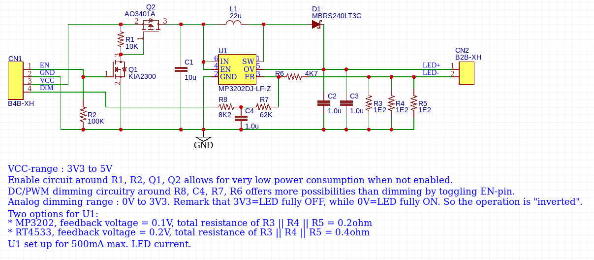
dimming capability (analog & digital dimming are explained in the MP3202 datasheet)
In the hindsight, the LM3410 would have been a better option, because it allows for larger drive currents.
Revision 1.0
Details about this circuit can be found on EasyEDA.
The circuitry above has some issues:
Thick wires must be used for VCC & GND because they have to carry up 1.1A. These wires will probably too thick to fit in the JST-XH. For debug, I soldered thicker wires on bottom side.
The current is set for 500mA, but only about 400mA is being drawn. The feedback voltage never reached 200mV. The 0.4ohm sense resistor combination had to be replaced by a 0.5ohm (2x 1ohm) resistor combination.
Value of the resistors for analog dimming are too big. As the PCB is quite small, they pick up some noise. Making them a factor of 10 smaller improves it a lot.
The RT4533 announces itself as boost converter for 10W LEDs 10 WLEDs. It's important where you put the space. Richtek means you can drive 10 white LEDs. It's easy to misread it as : "RT4533 can drive 10W LEDs".
It may well be possible to drive LEDs, but not at 10W. Let me explain:
The maximum input voltage for the RT4533 is 5.5V
The maximum switch current is 1.2A. For a boost regulator, this is also the maximum current through the inductor. The current through the inductor is essentially the input current to the circuit.
So maximum input power is 5.5 * 1.2 = 6.6W
Let's be optimistic and assume the output power is 80% of the input power : 5.3W, which is far from the advertized 10W.
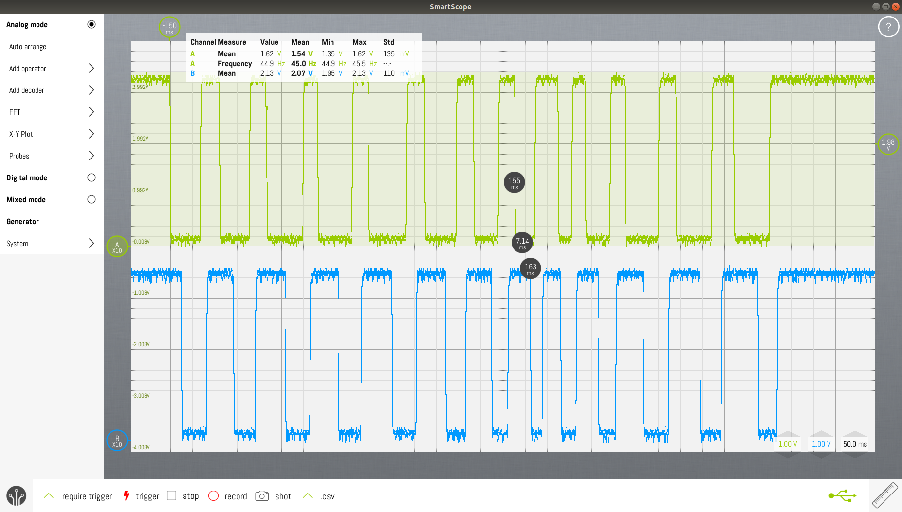
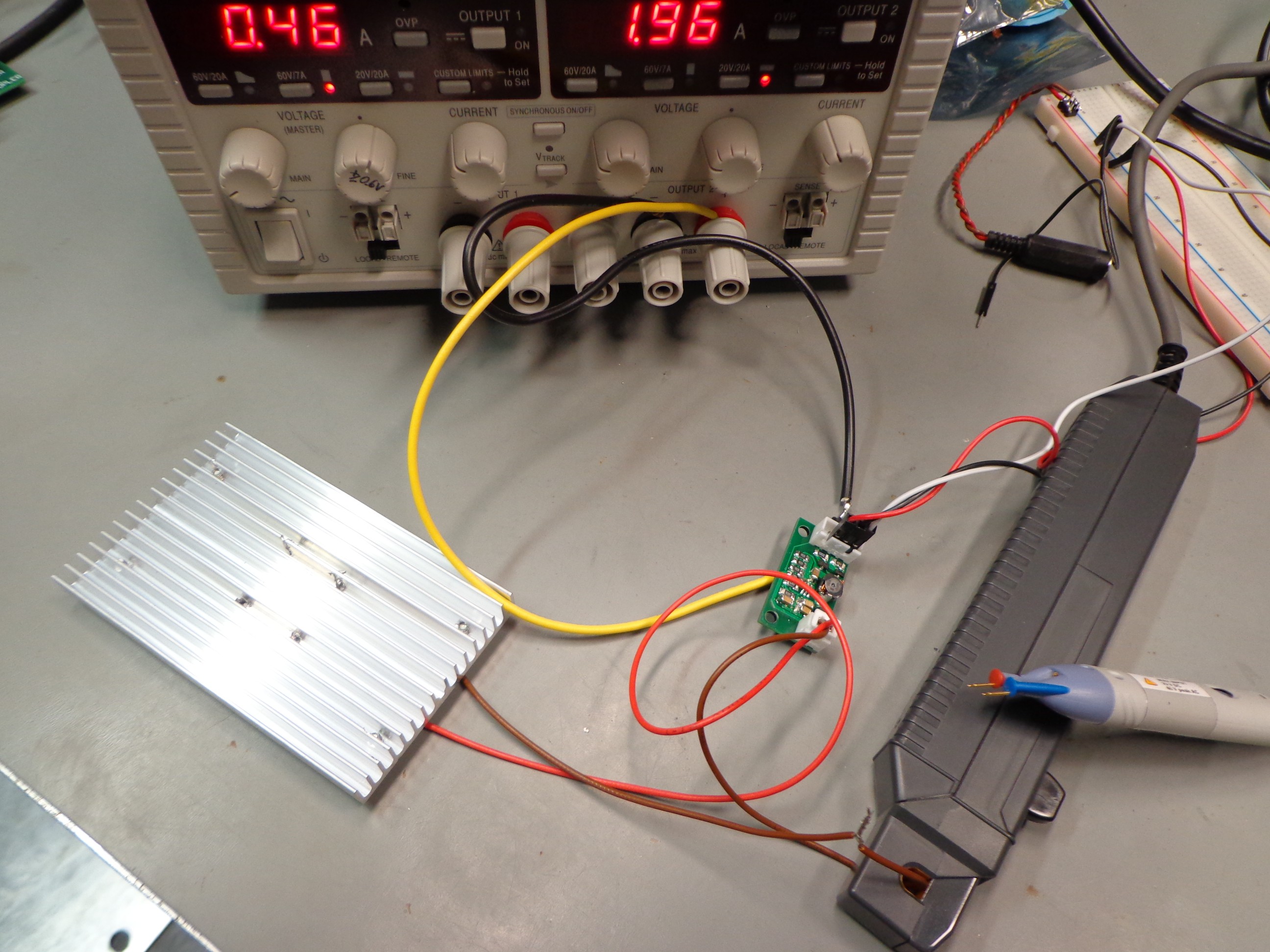
Measurement setup: dual power supply (set to max. 1.96A. Voltage output was disabled when picture was taken), R&S Current probe, R&S differential voltage probe.
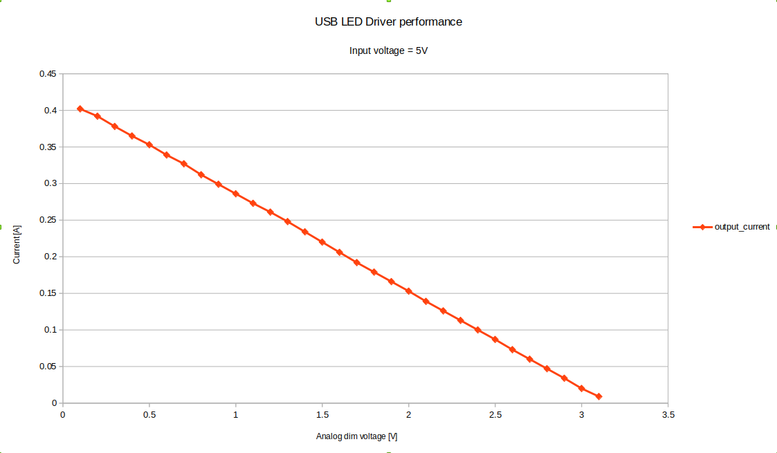
Measurement results
The output current drops linearly with the control voltage, as expected.
Efficiency is around 80%, as shown on the RT4533 datasheet.
The module already saw a second use as a replacement driver for lighting the christmas tree. The original driver was specified for 32V/100mA. Setting the two sense resistors to 3.9ohm and you're done. Power draw on the 5V power supply was about 800mA.
Dimming the light using PWM
Earlier experiments with dimming LEDs showed me that 8bits is not enough to generate smooth transitions. The step from 1/256 duty cycle to 2/256 is very noticeable. Once you're at duty cycle 200/256, increasing the duty cycle doesn't make much difference.
A simple way to increase the PWM resolution is to use two PWM channels, a dual RC-filter and an opamp. Hackaday already published an article about the subject.
Needed output power
A Philips HF3463 sunrise clock uses a Philps 100W 1200lm Softone lamp. Replacing the bulb with a 60W 700lm still gives enough light. So our light should also be able to output about 700lm.
Selection of the lighting source
Lumileds Luxeon 3535L & Lumileds Luxeon 3535L HE Plus
Disappointing output : 80Lux at 1m, I=500mA, U=17V
GU5.3 Base fitting for MR16 lamps
12V lamps
typically 500lm, which is rather limited
heatsink is part of the lamp
AliExpress has many on offer, very cheap
In a local store it was hard to find LED lights with a GU5.3 base. GU10 (230V) is the most common type of lamp. The best GU5.3 base LED lamp suitable for this application:
Philips
8W
12V AC/DC
€11.95 (no kidding)
630lm
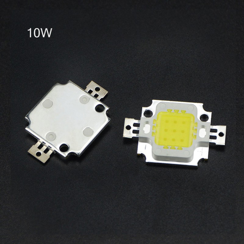
Wayjun Epistar 10W
available on AliExpress from many vendors
commonly used in floodlights
cheap : $0.29/pce (cheap version 900mA), $0.94 (real version 300mA)
A sample of each has been ordered. I received both but don't know which is which. I asked the seller and they replied that the "heavier" one is the real one. The "real" one is indeed about 4g heavier.
They were both announced as warm white, but the "real" one is cold white.
The warm white one has a terrible thermal efficiency. Without heat sink, the current needs to be lower than 100mA, or the LED will run too hot (>70°).
The light output of the warm white one is disappointing too.
The cold white LED performs a little better, but it's still disappointing. Too much of the power is lost in heat. These LEDs can't be used.
AliExpress "specs"
limited efficiency : 58lm/W (worst case for the cheap version)
11V, 1050mA, 675lm
heat sink needed
Backlight panel
expensive: 100x100mm = €3.84
limited light output
220V light with dimmer
requires 220V, which could be dangerous
consumes a lot of power because of the inefficient lamps
NeoPixel ring
No need for color changing the light
Controlling the room light
Standard light with controllable dimmer: You need a dimmer that can be remotely controlled
Philips Hue White Wireless bulbs : if you have a lot of money to spend
LED string
Inefficient because of the many series resistors in the string
Light source cooling
The above mentioned LED COB sources require that the aluminum substrate is not hotter than 70°C. If we want to maximize light output, we'll have to add a heat sink to get rid of the excessive heat.
There's no reliable info about the thermal resistance of the LEDs. Some tests will need to be done:
Attach thermo couple to the LED strip
Measure room temperature T1
Leave LED panel hanging in free air. Don't lie it flat on a table or other surface.
Attach current source to the LED and regulate current (I) so that steady state temperature of Al-substrate of LED is 70°C (T2)
Measure voltage over LED (U)
Calculate thermal resistance of LED panel = (70-T1)/ (U * I)
This is not the cheapest heat sink around. Care should be taken to the thermal resistance of the heat sink. The LEDs can work up to 85°C. Any hotter and their lifetime will decrease rapidly. At a room temperature of max. 40°C, this allows for an extra 45°C temperature rise due to LED heating. The total resistance of the thermal path should be smaller than 45°C / 10W = 4.5°C/W. The thermal resistance of the LED is already 1.4°C/W. This leaves about 3.1°C/W for the heat sink.
AliExpress vendors don't publish the thermal resistances of their heat sinks. We'll have to measure thermal resistance by ourselves.
Another way is to go with some simple rule of my old colleague : "If your heat sink is too hot to touch, then it's too small".
LED animations are nice, but they shouldn't stand in the way of functionality. The DOTKLOK has very long time transition animations. This will get annoying real soon.
Some of the clocks show the time up to second resolution. For a bed side alarm clock, I don't see a point in doing that. Besides, how accurate is the clock anyway? If the clock is not regularly synced to some time source, the shown seconds will be incorrect. Second resolution is useful in timers (for cooking etc.), but an alarm clock is not a timer.
Xronos Clock The idea of the arcade buttons is good, but the menu navigation is quite unusual. The black button cycles through the menu items of the top hierarchy level. The red button is used to go from top hierarchy to the level second level. Then it cycles through the menu items of that second level. The white button finally is used to change user settings. As there are only three buttons, you can only cycle in one direction through the items. For setting the year or the minutes of the hour, that's quite annoying. A fourth button would have made menu navigation a lot more intuitive: up, down, select & back.
See how long it takes and how many key presses are needed to set it all up?
Has a brightness setting for day, night and allows setting brightness level for day/night transition.
It's personal taste, but :
I dislike the use of a different color for each digit.
Why design & 3D-print a RECTANGULAR housing? Choose a COTS-housing, design your electronics to fit that housing, make cutouts in the housing where needed.
 Christoph Tack
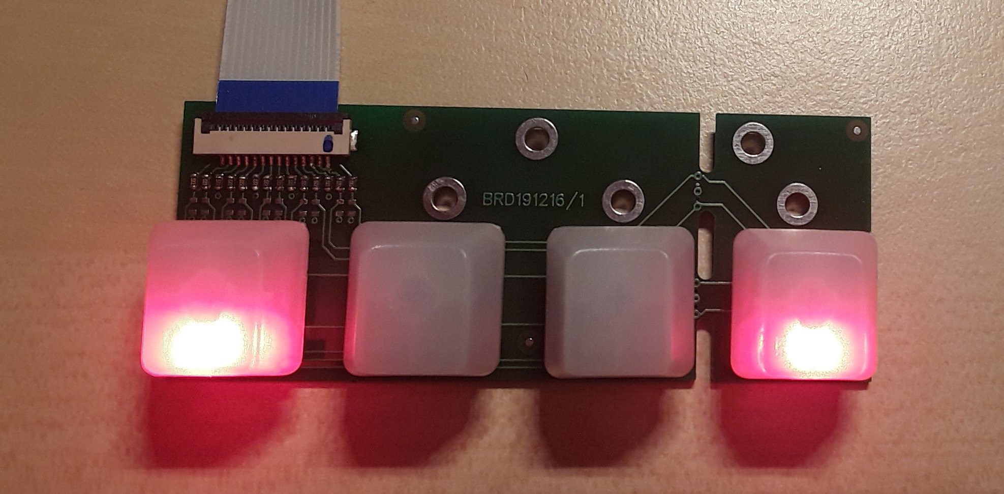

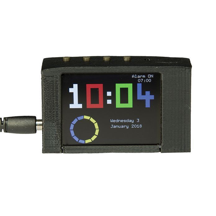
 3-Way Display Alarm with 2.2" TFT