Roman
Roman-
Data Representation in the Handheld Lab
02/24/2016 at 20:45 • 0 commentsData is stored and processed in a fixed-point representation. In a fixed-point processor, numbers are represented and manipulated in integer format. In a floating-point representation numbers are represented by the combination of a mantissa (or a fractional part) and an exponent part. In a fixed-point processor, one needs to be concerned with the dynamic range of numbers, since a much narrower range of numbers can be represented in integer format as compared to floating-point format.
Q-format Number Representation
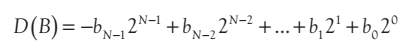
The decimal value of an N-bit 2’s-complement number, B = bN-1bN-2…b1b0, where bi is either 0 or 1, is given by
![]()
The 2’s-complement representation allows a processor to perform integer addition and subtraction by using the same hardware. When using the unsigned integer representation, the sign bit is treated as an extra bit. Since my device have to be able to measure positive, negative, as well as AC signals the numbers are represented in sign magnitude format. This allows me to keep track of AC signal for automatic switching between DC and AC measurements. Converting 2’s complement values to sign magnitude requires processing time, but with 16 MIPS speed (PIC24FJ256GA110) it is unnoticeable.
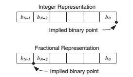
There is a limitation of the dynamic range. For the 24 bit data (MCP3911) maximum positive value is +8388607 and max negative value is -8388608. These values represent number of steps in positive and negative directions. Measured values are represented in Nano-Volts and Micro-Volts, this allows me to keep high resolution of a measurement. To display measurements in Volts I move decimal point accordingly. This representation scheme is referred to as the Q-format or fractional representation.
bN-1 2N-1. bN-2 2N-2 … b1 21 b0 20 Volts or Amps.
![]()
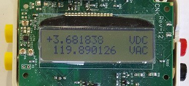
The binary number gets converted to a string of characters to be displayed.
![]()
-
PIC24FJ256GA110 ADC config file.
02/23/2016 at 03:07 • 0 commentsvoid ADCH0_init(void){ _ADSIDL = 0; //FORM<1:0>: Data Output Format bits _FORM0 = 0; _FORM1 = 0; //SSRC<2:0>: Conversion Trigger Source Select bits _SSRC0 = 1; _SSRC1 = 1; _SSRC2 = 1; _ASAM = 1; AD1CON2bits.VCFG = 0b000; // VR+ = AVDD, VR- = AVSS _CSCNA = 0; // 0 = Do not scan inputs. _BUFM = 0; AD1CON2bits.SMPI = 0; _ALTS = 0; _ADRC = 0b0; // 0 = Clock derived from system clock AD1CON3bits.SAMC = 0b00001; AD1CON3bits.ADCS = 0b00000000; AD1PCFGLbits.PCFG0 = 0; // Set AN0 as analog channel. _CH0SA = 0b00000; _AD1IE = 0; _SAMP = 1; //Start sampling }It looks like I get less then 500 ksps, need to go through the code and figure out why.
-
Input impedance verification test.
02/15/2016 at 18:05 • 0 commentsJust tested to verify the input impedance and it shows to be 10 Mega Ohm. Apparently the input low pass filter drops it from 20 Meg down to just a little over 10 Meg (2% above 10 Meg). Need to improve it. The goal is toget higher impedance, significantly above 10 Meg. My Fun continues.
-
Improvement of the calibration process.
02/11/2016 at 11:11 • 0 commentsThe current calibration procedure needs an improvement. I found that maximum deviation from a true reading can be as high as 0.69%. The goal is to get better than 0.2%. The current calibration procedure is done on computer. Computer takes voltage reads from the multimeter, stores them, then computes appropriate calibration values and writes them into nonvolatile memory in the instrument. I believe a more accurate calibration values can be obtained if the calibration process does not involve a computer. I t has to be done on the handheld device itself.
-
Bluetooth NRF51822 wireless link
02/07/2016 at 20:07 • 0 commentsI am starting to work on my wireless section of the project. I am planning on using NRF51822 Nordic chip. My choice of development software is Keil Development Tools uVision. Keil has a lot of examples for NRF51822 Bluetooth chip. I have my own board I have designed some time ago, but I am planning on using off the shelf board, something inexpensive.
Multimeter +
Dual input 24 bit Multimeter with USB interface, single channel 10 bit USB oscilloscope, PWM out, 2 Ch Data-logger, R, C, Digital sniffer.