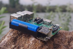
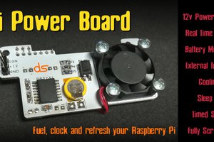
Update: I've got the final version 1.X design done. It removes a few minor mods and adds a direct battery port for my upcoming Pi Zero dual motor driver boards. V2 will have a battery "fuel gauge" for safer battery operation.
In my earlier logs, I mentioned a "version 2." I changed the numbering so that everything to date is a v 1.X.
Update: I do have a Pi Zero in hand now. I've also considerably reworked the design. I put a P channel MOSFET on the power line going into the MCP73831 LiPoly charger chip, which is the Pi 5 volt line. The power line out, has a Schottky diode, and then goes to the Pi 5 volt line. I use a comparitor across that diode to switch the input MOSFET on and off.
I put a P channel MOSFET on the power line going into the MCP73831 LiPoly charger chip, which is the Pi 5 volt line. The power line out, has a Schottky diode,and then goes to the Pi 5 volt line. I use a comparitor across that diode to switch the input MOSFET on and off.
If I'm running from the Pi, and charging the battery, the cathode of the diode has 5 volts, while the anode has the about 4 volts coming out of the charger chip, keeping the comparitor off. When I disconnect the Pi power supply, The anode has the 4 volts from the battery, and the Pi 5 volt line has that, less the voltage drop from the diode. This sets the comparitor, which turns off the MOSFET. That way, I won't be feeding a low voltage back into the charging chip when running from battery.
After the Schottky diode drop, I get about 3.7 volts on the Pi 5 volt line. That's enough for the 3.3 volt LDO regulator on the Pi. Most 5 volt peripherals won't be able to run, but the Pi and 3 volt peripherals will be fine.
[Pre update]
So... What were those assumptions I spoke of?
I assumed that, since the Pi is basically a 3.3 Volt device, I should put a regulator on my board and power the Pi via the 3.3 Volt line. With this being the case, I would run the 3.3 Volts on my board through a P-Channel MOSFET. The gate of the FET would be controlled by the 5 Volt power line. If the Pi has a 5 Volt supply, my board wouldn't supply power to the Pi. If not, it would.
What got me is that when you run power into the Pi 3.3 Volt line, there is still high enough voltage on the 5 Volt line to switch the MOSFET off.
With a bit of research and experimenting, I determined that the LiPoly batteries supply at a voltage level high enough to get through the Pi's low drop out 3.3 Volt regulator. Version 2 of my board removes the voltage regulator and puts in a comparitor to switch the MOSFET.
 Duane Benson


 Patrick Van Oosterwijck
 Giuseppe
 Dan Julio
No schematics? Would be great to take a peek