Like what you see? Support me on Patreon.
5+ Axis Robot Arm
Building an open source robot arm for makers and small businesses
Building an open source robot arm for makers and small businesses
To make the experience fit your profile, pick a username and tell us what interests you.
We found and based on your interests.
Like what you see? Support me on Patreon.
This project is now retired as I have moved (Since November 2018) to a 6 axis model. Please follow this link to find out more: https://hackaday.io/project/164755-sixi-2

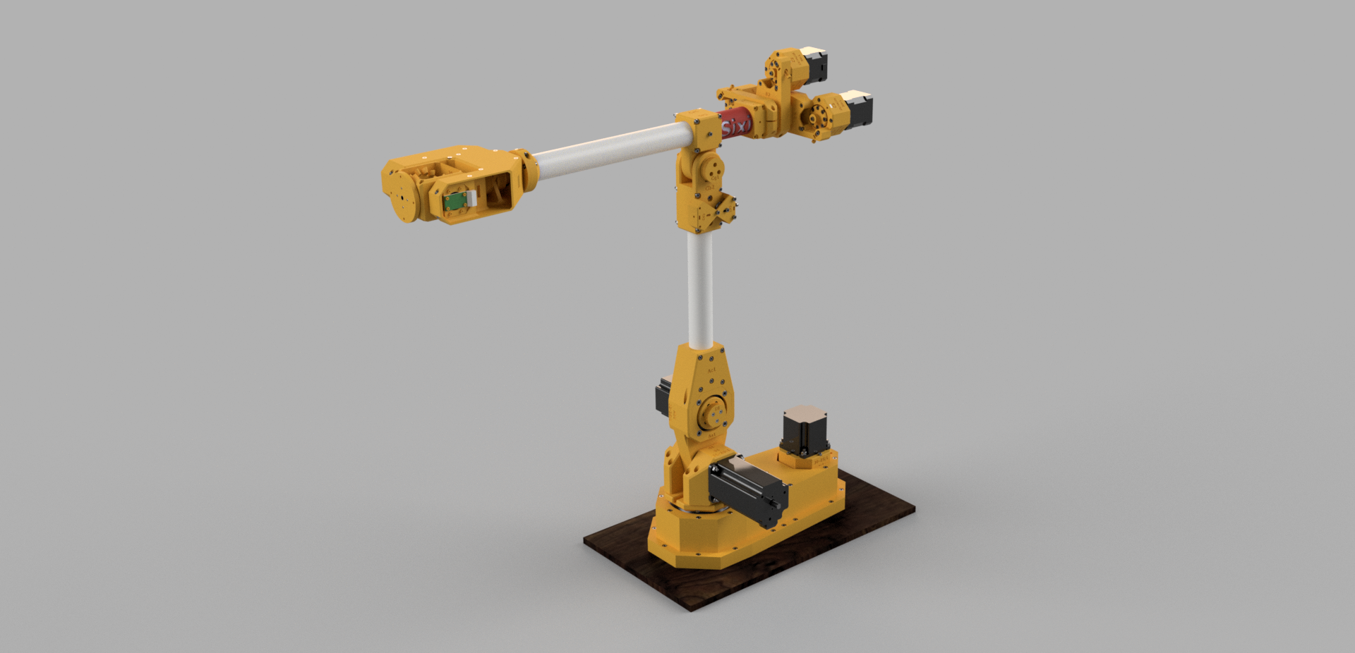
Thirsty for robots? Say no more! This is a render in Fusion360 of our up-to-date model of the Sixi 2 robot arm. All the Fusion360 files are available through my Patreon so you can get started making it today.
Also the Robot Overlord app has been updated to do IK and FK calculations on the arm, meaning it will be easy to train it for various applications. My first goal is to make it pour a beer. My second is to work on self assembly. If I can get these arms to assemble their sisters... it's the last time I'll build a robot by hand.
You can follow my weekly progress reports on my blog or through my youtube channel.
https://www.marginallyclever.com/2018/07/can-machine-learning-improve-robot-kinematics/
I'm trying to use Machine Learning for robot path finding. Read all about it at the link above.
I was up until 4:30am last night working on the fifth attempt to design the arm. Previous post on HAD.io were of (at best) study 4. I reached a point in the design where I'd found enough mistakes that it was easier to restart and use the existing design files as a reference to do a better job. I believe that - after three days of work - I've got something that solves all my previous issues and has fewer prints.
With lessons from the previous attempts, this time I built things in large passes:
place all the things that can't be negotiated (bearings, motors, screws in motor faces)
Speaking of BOM, here are some stats:
Cost for raw goods and DIY printed parts is matching my expectations. The long pole is the 8 larger bearings. I got them from VXB.com and they're about $250+shipping. Ugh!
So for day to day updates, follow me on Instagram.
Become one of my Patreon supporters today and you get early access to the Fusion360 files. Build this yourself! Contribute ideas! Automate all the things.
Bicep parts are all printed. I have to collect a number of missing fasteners and wait for bearings to be delivered. In the meantime I'm going to assemble the circuitry for the controller and run some tests on a rotation sensor idea that's staying under wraps for now.
Here are some pics from the 6 axis model I'm currently working on.
https://www.instagram.com/p/BaPQChtgkqp/?taken-by=imakerobots
https://www.instagram.com/p/BaK56pIg09m/?taken-by=imakerobots
https://www.instagram.com/p/BZuFjqrAWwr/?taken-by=imakerobots
As I print and assemble each part I check it against the model. More efficient than building an entire model in a vacuum and finding I made mistakes. Maybe it couldn't be done without an existing, purely-vacuum model as a reference. Hard to say from the other side!
The design files for this version are on Patreon. https://www.patreon.com/imakerobots
You can wait until it's for sale or chip in a little now, get the files early, and support development. Your call.
I'm always thinking about building the arm and life laughs at my plans.
I'm currently building several robots as commissions; running Marginally Clever.com; and spending a lot of coding time on Robot Overlord. I've got newly designed AS5045 sensors that work well, they now need to be integrated into an updated arm design. I may actually repurpose those sensors in another project first: A new Stewart Platform being built for a local science museum.
https://www.instagram.com/p/BOim_CBjiaU
The biggest problems with the last arm design all stemmed from poor sensor construction.
- the wires were exposed to users where they could catch, fall off, etc.
- the sensor and magnet have to be held in perfect alignment or the arm loses sensation and goes nuts.
To fix that I'm working on a single sensor unit that I can test independently and use as needed in my next arm.
I'm deep into preparing for a new product launch, and then finishing the Jigsolve. My winter project is to make a new arm and integrate it with Robot Overlord, which still needs a way to record/play back every robot it supports. I'm also putting together a team to build a new game based on my design doc, which should eat ~6 months and cost ~100k.
All of which is to say I'm really busy and I need all the help I can get. I'm looking for talent everywhere.
There is a growing number of open source robot arms, which is super. I only build one because I can't get one at an affordable price. So if you're making an arm, please let me add Robot Overlord support and together I hope we can achieve greater things.
Soon.
Create an account to leave a comment. Already have an account? Log In.
There's a more comprehensive video update on the effectiveness of prtototyped strain wave and hypocycloidal gears at https://hackaday.io/project/19405-strain-wave-gear-with-timing-belts/log/86936-catch-up
Hi Simon, impressive! I was wondering why you took the timing belt on your last attempt and did not print the teeth into the outer ring. I could imagine that The timing belt is useful for dampening the whole thing, but it might also increase the backlash.
I think backlash is definitely a concern but I think the wear will be less if we start with belt against printed cycloidal disc. If we use printed ring pins against printed discs, it will wear out faster.
True... Still I'm wondering why most of the hypocyloid drives work with pins instead of two simple gears, the fixed one with internal toothing and a regular one with the excentre in the middle. In total, this requires 4 bearings only and no pins (although I must admit that I did not yet build it yet)
Traditional gear teeth profiles aren't suitable for the hypocycloid motion - it's all curves. So making inner and outer gear teeth with those profiles is unlikely to suit traditional gear cutting tooling (I'm totally guessing here). Drilling or otherwise machining holes or slots and slotting a pin in to take care of the radius (at good precision and hardness and relatively low cost) is probably how pins ended up in these gears commercially. Total guesswork though!
I tried to design it in inventor (with involute curves instead of hypocyloid curves). What seems to work in our situation (diameter of 5cm, teeth height of at least 2mm (module 0,8) is a ratio of 120 teeth to 112 teeth which gives you 1:15 gear ratio after all. If I try to increase the gear ratio (my goal would be 1:20, since that is what I required in my bot Walter), either Inventor claims that the involute curves do cut themselves or the teeth need an unprintable small height. If you accept a diameter of 80cm, 1:20 is achievable.
BTW: do you consider to integrate an encoder?
50mm is pretty small, both for manufacturing with standard FDM and M3 hardware, but also for the pressure on your teeth and the strength limitations of using plastic gears. 80mm is more like it but I worry that even that will be unable to take e.g. 20 Nm (unless perhaps you use stronger filaments that are harder to print).
I did think about the encoder - see the link I posted above about the "hoverboard" motor and the BLDC I linked to below. Both would need encoders for phase control of the ESC. However, I think you're talking about an output shaft encoder for closed loop control. Thinking about this but I'm not actually making an arm, so it would really depend on the control system that each builder was using. There's definitely potential to build one in to the mechanism, away from the motor perhaps for a magnetic sensor.
my shoulder arm had a max torque of 30Nm, but I used T2.5 timing belts, meaning in average I had 40 teeth to take the force, equally distributed by the belt. But backlash is poor (arround 3°). I could compensate that with a closed loop via encoder and a fancy non-linear controller, but I never felt comfortable with electronic compensation of a mechanical issue. In my current sketch with 140 / 148 teeth typically 15 teeth would take the force, but very much relying on the print-precision, and not equally distributed. Finally, I think that your idea of a having a timing belt as internal gear would improve force-distribution across involed teeth a lot. I print with high-temperature ABS, never had an issue with broken teeth in T2.5
It would be interesting to see whether a change in belt profile from T2.5 to HTD or GT belts would make a difference on its own.
I agree it is far more satisfying to start with if you can explore the solution to mechanical issues with mechanical interventions but at some point the cost/benefit of the precision required for a given performance can make compensating electronics very attractive as a design investment!
It was interesting to hear about your belt gear setup but my point about the strength of printed parts was more to do with how you interface the torque output to the lever and load, not the strength of the teeth. On Walter and other arms, the diameter of the belt gears is quite large to achieve your desired ratio (so force of torque is reduced at increased diameter) but if you look at Dan's prototype hypocycloidal gear (https://www.instagram.com/p/BeTiii_gDm_/) if any of that was experiencing 20-30 Nm and was 3D printed I would worry about deformation of parts, especially holes where bolts go in. Increase the diameter and the forces naturally reduce, so we just need to be aware of those limitations for now. Perhaps if you hit upon a winning design you might go for resin casting or CNC machining from e.g. acetal/delrin or HDPE sheet.
Hi guys, if the 3d plastic is too weak, I can recommend to reenforce it with carbon rods that are glued into designed holes. I got this trick from the Dexter arm/Haddington. This makes it much stiffer and eases PID tuning, since this dampens the osscillation as well. I had a hard time in tuning the PID to different load-situation: tuning it with a small load is easy, but higher loads need different P&D factors. When gravity force varies as well due to joint angle this gets even worse.
@Jochen Alt thank you for the tip - it's great to hear from someone who has been through the whole design - realisation process. I'm still stuck on printing gears but your idea of reinforcement is definitely applicable if we start hitting the mechanical limit of printed gears before the motor stalls.
@Dan Royer have you considered these BLDC motors with planetary gearboxes and encoders?
The driver appears to be included, in that you control through PWM, direction logic line and start/enable logic line. Looking at the sizing, if you can live with lower RPM on your output stage, they would appear to be small/light for a given torque rating. For example, your 20Nm application might select the GSP42M530SH316. At 24V, rated for 18.8Nm at 3.8 RPM, with a max torque of 28Nm (presumably slower RPM/stall torque).
In comparison, I can't tell from your instagram post of the motors when they arrived but it looks like a geared NEMA 23, such as:
would be a torque equivalent(ish). It's 1.7kg vs 0.5kg for the BLDC. I think you're using this one at the shoulder(?) so the weight is less of an issue but that pattern probably scales down to the smaller units. Also don't know what RPM a 47.1 geared down NEMA 23 output shaft could achieve.
I realise that none of this addresses any potential backlash of the planetary gearboxes and you'd perhaps want to combine (ignore) the input encoder built into the BLDC with (in favour of) encoders on the joints for closed loop but they seem roughly the same cost ballpark and through reduced mass may help reduce the moments your lower(?) degree of freedom joints will have to overcome.
I appreciate that you put in all that research! At this time motor torque and arm moment are not yet an issue. The bones of my last design are two weak, the motor keys tear through the plastic. I have zero experience with tuning PIDs to get straight line motion with DC motors.
That's interesting - one advantage of a 3D printed hypocycloidal or strain wave gear is that it allows you to transfer torque without high forces near the axis. I'm sure a keyed shaft adapter wouldn't be too hard/expensive to make. Is that something near the top of your list?
And by "last design", are you talking about Study No.5?
I have no idea about PID tuning DC motor drivers either but I reckon it wouldn't be too hard (if you were to use what's already out there, building on the shoulders of giants etc). By "straight line" do you mean of the effector, i.e. the reverse kinematics part? Could it be set by encoder pulse inputs, rather than coordinating motor step output pulses?
Hi Dan, when you were coming up with your design, what did you think about strategies to move the motors further "back" to reduce the moments? Did the motor masses become less relevant once you set yourself a 2kg @ 50cm payload constraint, or could the mass help counterbalance the arm and payload?
iforce2d on YouTube has been attempting a design that you might find interesting.
One of the other reasons it might be worth using belts or concentric tube drive shafts to move the motors "back" is that you could remove the motor axle from the pivot axis at key joints and avoid those BoM-busting bearing prices!
For my part, I'm hoping to soon find time to video the latest (nearly a year old!) timing belt strain wave gear. It's OK but I'm not sure how much it will handle higher moments with rubber belts. I saw the recent AvE video on the hypocycloidal(?) Japanese gear and am inspired. Maybe a cnc plastic version with small deep groove bearings is feasible?
What I think is "how?" Either I use gearing, which doesn't work over long bones; or timing belt, which is hard (for me) to tension and (I'm told) adds a harmonic vibration that reduces overall performance.
What are "concentric tube drive shafts"? link, please.
No bearing is more than $30. they're not really that bad. total cost of motors is greater.
I'm trying to make something that nearly anyone can recreate. The easier it is to produce, the better. So I've accepted that 3D printing is OK, but most makers don't have CNCs to produce bearings or metal adapters. I may have to bend and make one or two metal parts for sale.
I admit I haven't tried to tension timing belt and wasn't aware of the harmonic vibration.
Not got links for the concentric shafts but given the hollow "bones" I thought it would be a good approach for rotational transmission. The idea is to nest one, say wood/carbon/fibreglass dowel or tube inside say a PVC or polycarbonate (slightly shorter) tube, separated by a radial/deep groove bearing. A second pair of larger bearings holds the outer tube in the arm. There's a motor coupler on one end of the inner shaft and a drive gear/pulley on the same end of the outer shaft.
On the "far" end of the inner shaft you could transfer rotation to the next bone, perhaps with a universal coupler (https://hobbyking.com/en_us/universal-drive-shaft-coupling-for-boat-23mm-x-3-17-4mm-2pc.html) and a drive gear/pulley on the outer tube to drive the joint at that location.
I've wondered about two similar shafts in parallel instead.
I see the bearings aren't individually expensive now.
Without going too off-topic, I know you are considering encoders in future. What kinds are you thinking would be on the shortlist?
This design has some interesting approaches to keeping the motor mass closer to the previous joint https://youtu.be/_j2eKYnCMvw
I think there's even a concentric drive in the forearm - see two steppers at the elbow.
Hey dan! Like the iterations in this! Curious about angular measurement, are you using any encoders? Or using steppers with encoders? And yes, printing iterations for tolerance is definitely annoying. I've just added it as a variable in my fusion360 designs :)
in my current iterations the robot is totally blind. once I've proven the basic mechanics I plan to add first some limit switches, then some encoders. One problem at a time :)
I also use a printerMargin value. I'm not in love with it. I'd love a CAM option to add tweaks after design and before printing, so it can be better tailored per-machine.
Right on :) Also, it looks like if you could cnc some of the bigger sections out of hdpe or something for quicker testing?
Nice Project! But I wonder if you are giving a way much strength and stiffness by using open cross section profiles (H and C) for the arm. In my experience constructions made out of plywood and with finger joints are much stiffer if they are closed all around. Holes in the walls are often not a big problem but missing walls weaken the parts notably - especially wrt (lateral) torsion.
It is a bit difficult to judge just from the pictures but it also seems that the different axis of the arm have different strengths - limiting the capabilities to the weak ones. Especially the NEMA17 motor for the first axis looks much weaker than the linear actuators for axis two and three, given that is also has to deal with the full length of the arm as a leaver.
It's a bit of a pity that you do not have a video with the arm under load or fast movement, so the strength and stiffness is more visible.
If you want it to be cheap use 3d printed pneumatics. Or just home built pneumatics from pvc pipe etc.
Counter-weights will get you more strength / $
they're in a zip in the Evil Overlord project so the arm can the rendered in 3D
Nice project dan. I am regular visitor to your marginally clever website to learn CNC basics and when i was looking for DIY robotic arm then i found you again here.. :)
Yes, It would be great if you post it to MC blog and link it to MC tutorials page.
Become a member to follow this project and never miss any updates

 Irene Sanz
 Kenny.Industries
 Rudolph
 Les Hall
Hi Simon what is the max payload of the robot?