Close
0%
0%

PiBoy-Zero

yet another portable console! ;-)
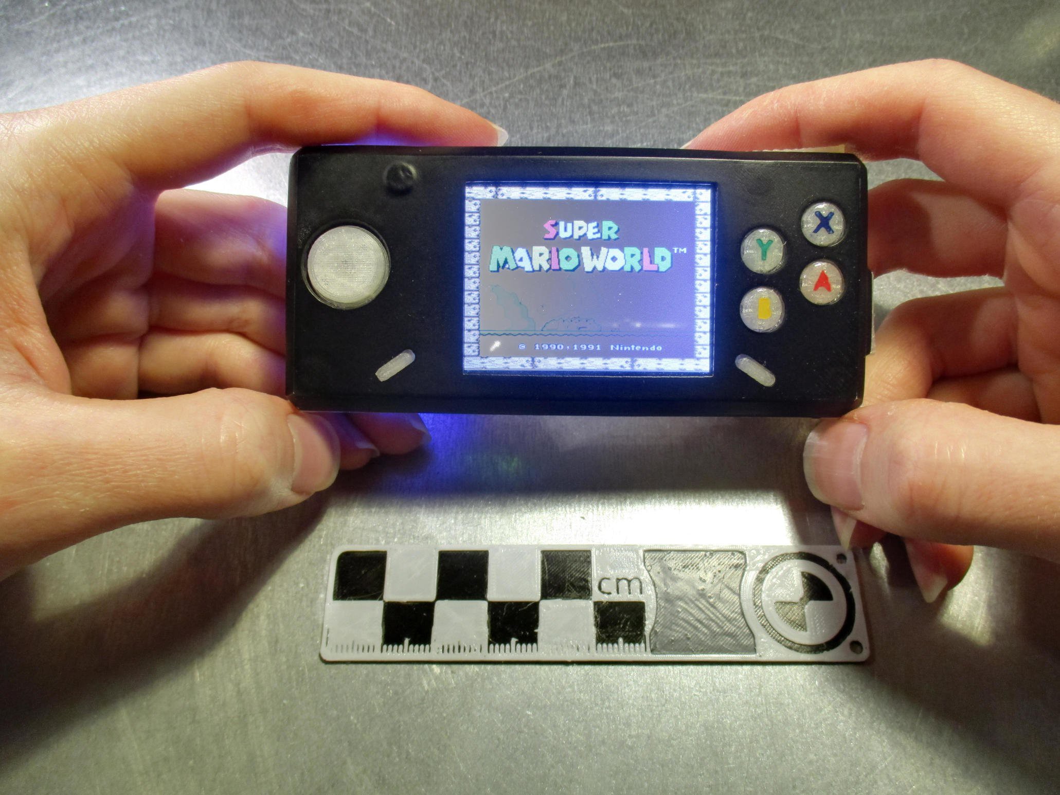
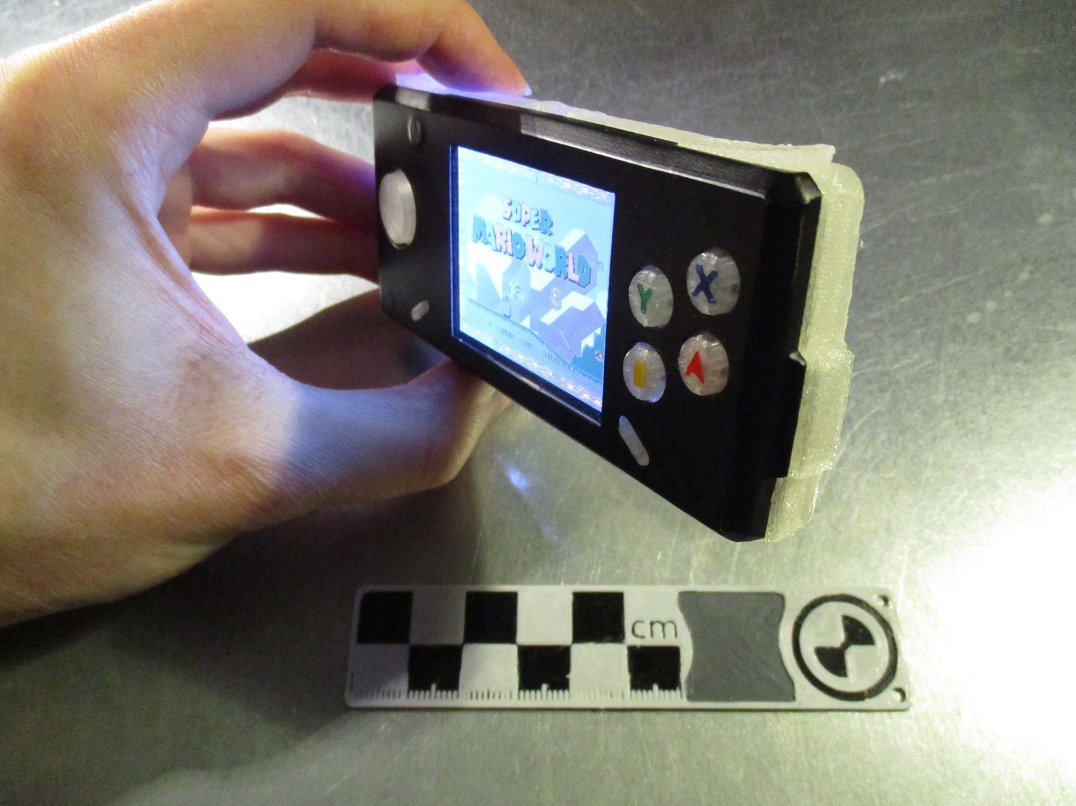
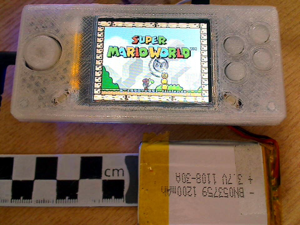
roughly the size of a gameboy micro, with a 2.2" display

Similar projects worth following
the idea is to build upon the great PiGrrl - a gameboy-like portable console that is raspberry-pi driven - but to use a single carrier pcb to reduce the size to a gameboy-micro like form-factor.

this project will build upon the open-source (thnx! :-D) plans for different adafruit products and their "learning"-resources to add the different features - and ultimately build a truly compact and portable console

some of the adafruit projects this is inspired by and will be based upon:
the original piggrl: https://learn.adafruit.com/pigrrl-raspberry-pi-gameboy
(its ancestor: https://learn.adafruit.com/game-grrl )
the pocket variant: https://learn.adafruit.com/pocket-pigrrl
and its second iteration: https://learn.adafruit.com/pigrrl-2


Design Goals:

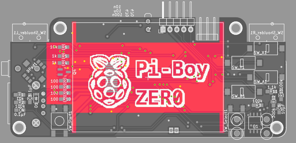
- reduce ratsnest of wires, done with a custom pcb

- use good-quality buttons with better "feel" instead of cheaper/harder 6mm tactile switches

- hand-solderable, using 0805 sized smd components and slightly longer pads on the pcb


Features:

- 2.2" 320x240 display (for comparison, the gameboy-micro had a 2"240×160 display)

- 3d printable case, with overall size: 48x103x21mm (gameboy-micro: 50x101x17.2 mm)

- power button, for controlled shutdown of the pi (via a pushbutton - push for on/off, hold to force off)

- audio-out (via pwm, like the raspberry 2)

- 1200mAh LiPo battery connected to an adafruit powerboost 500c

- USB-A socket (reusing the connector that comes with the powerboost pcb, connected to raspberry-zero testpads for USB)

- OS: raspbian running emulation-station (and some support daemons to tie in the hardware)


2016-03-13_BOM.csv.zip

x-zip-compressed - 1.08 kB - 03/14/2016 at 14:16

Download

2016-03-13_schematic.pdf

Adobe Portable Document Format - 163.38 kB - 03/14/2016 at 14:16

Preview

2016-04-02_pcb.pdf

Adobe Portable Document Format - 256.51 kB - 04/02/2016 at 14:20

Preview

View all 8 components

  • current state & ABXY buttons

    JohSchneider11/02/2016 at 18:14 0 comments

    been using the Pi-Boy on and off for the last couple of months - works beautifully :-)

    some things need to be redone though;

    - messed up front panel (heat-setting M3-thread *after* painting was a dumb idea...)

    - the power button needs a redesign (button-cap is missing)

    - have to add a bit material to the back/front to close the slight gap between the two


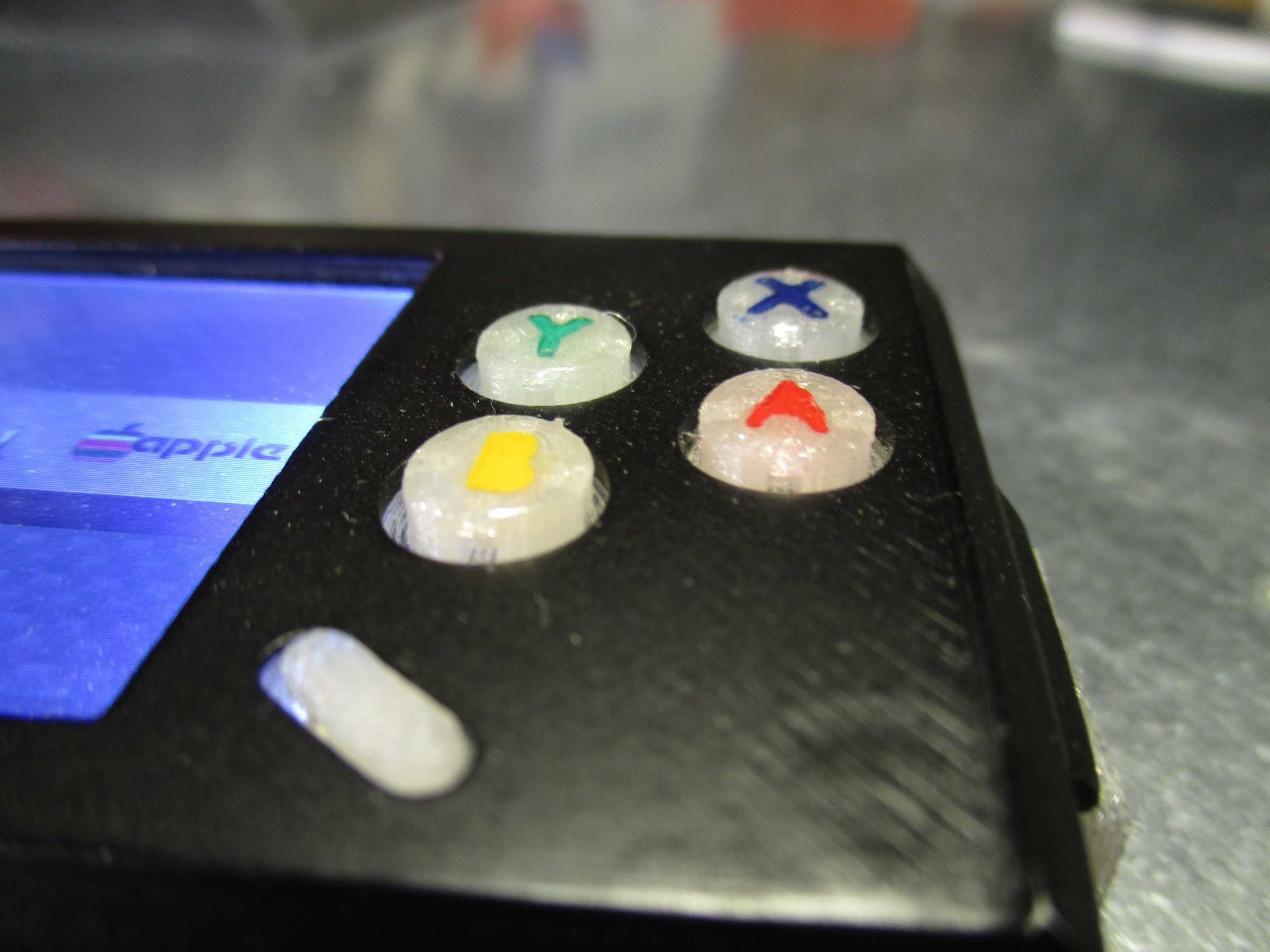
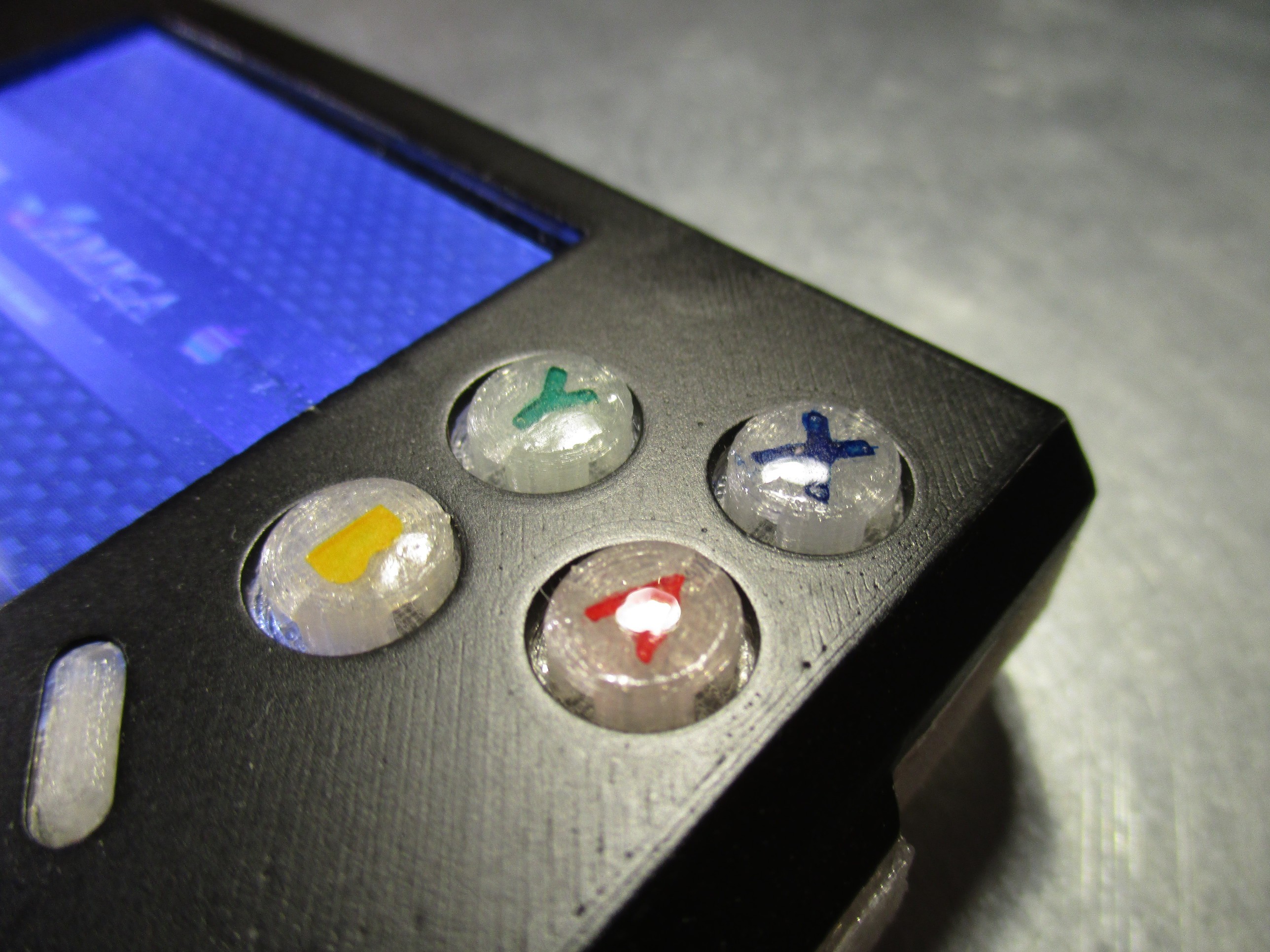
    on a side note: what turned out really well where the ABXY buttons - the combination of the soft-tactile omron switches plus a coat of epoxy feels just right while playing :-D

    the way i build them was:

    - print the button-piece (one part, all four are connected by a bridge - to ease assembly) with the letters indented

    - fill the letters with acrylic paint

    - put a drop of XTC-3D (some other epoxy might work too) on top to form a slight dome

  • milestone: it lives!

    JohSchneider04/09/2016 at 15:27 6 comments

    for the thirtieth log something special - it lives! :-D

    - battery: check

    - display: check

    - controls: check

    - sound: check

    all systems go:

    there are still many rough spots:

    - on the software side there are many daemons still missing (pwm back-light, power management, ...)

    - the system needs further configuration: the buttons currently only work in emulation-station menu, not the emulators (probably sth minor)

    - the case needs further refinement, lots of sanding, priming and a few layers of paint :-)

    - the setup/configuration steps need more documentation or better: scripted as far as possible (rough script already on github)

    - print and assembly instructions?

  • case prototyping

    JohSchneider04/09/2016 at 14:28 1 comment

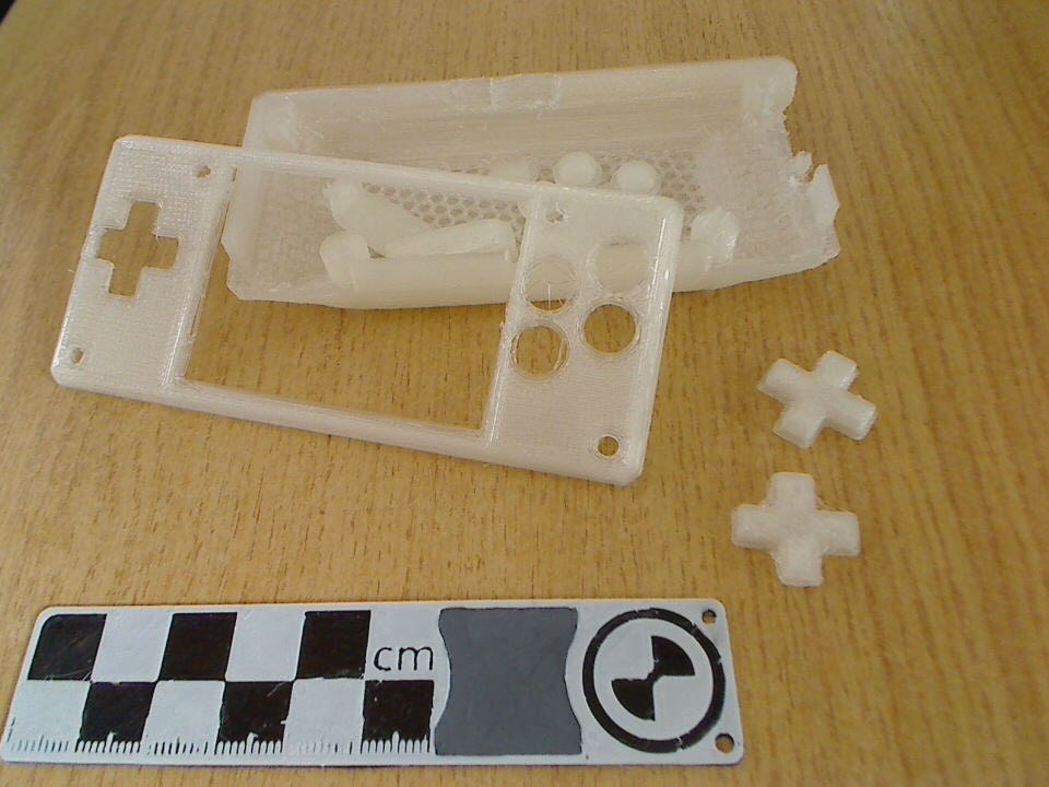
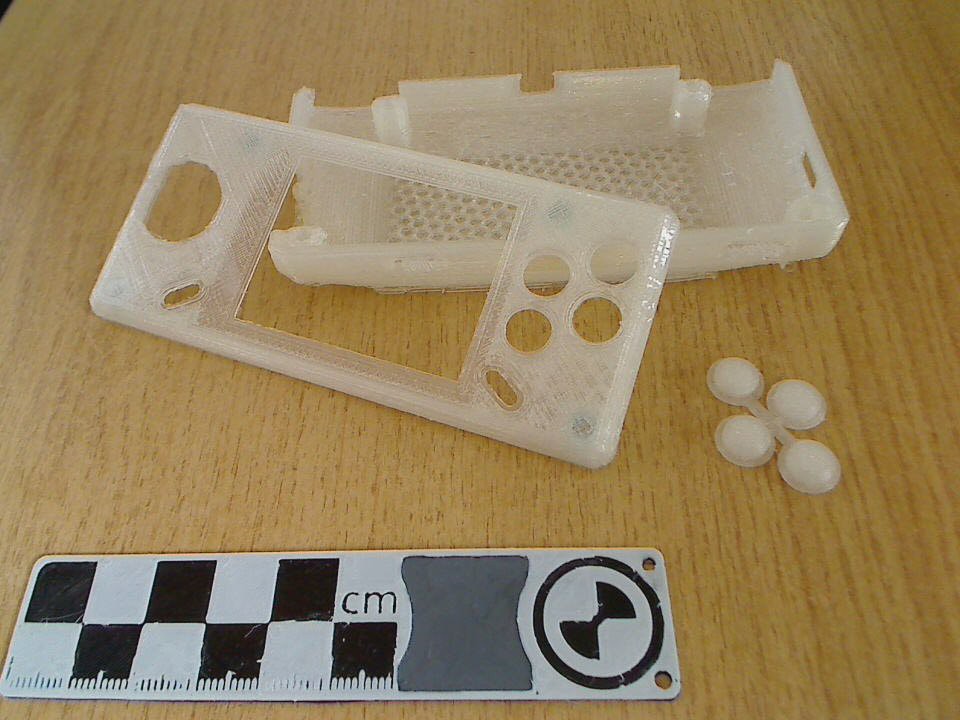
    creating a 3d printable case from the rough sketches done earlier

    the overall shape was put toghether relatively quickly - but getting the d-pad to feel right took some iterations, the first few where still cross-shaped

    turned out, that shrinking and making it round works better for the alps switch. connecting the ABXY buttons eases installation

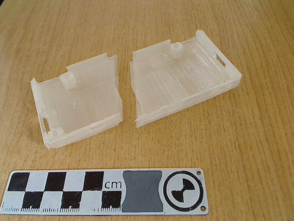
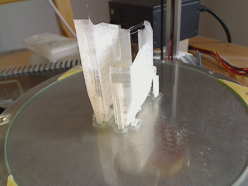
    also playing with the back part, for example splitting it in two with overlapping part along the seam:

    which would be printed standing up:
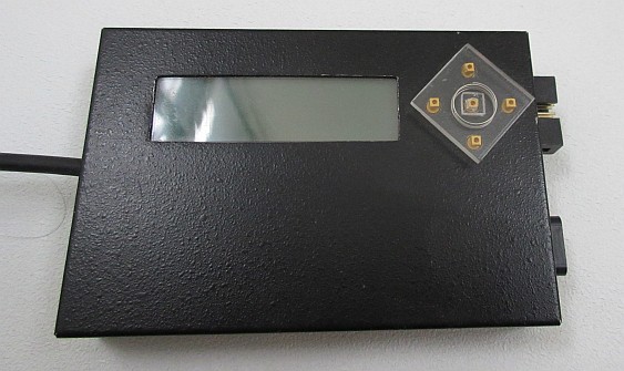
    this would have the upside of a sturdier frame - but on the downside prints waaay longer, with increased risk of print failure and the split/seam doesn't look as nice as a single-pice backside does, paintability would probably be another issue - so i'll stick with the single-piece for now

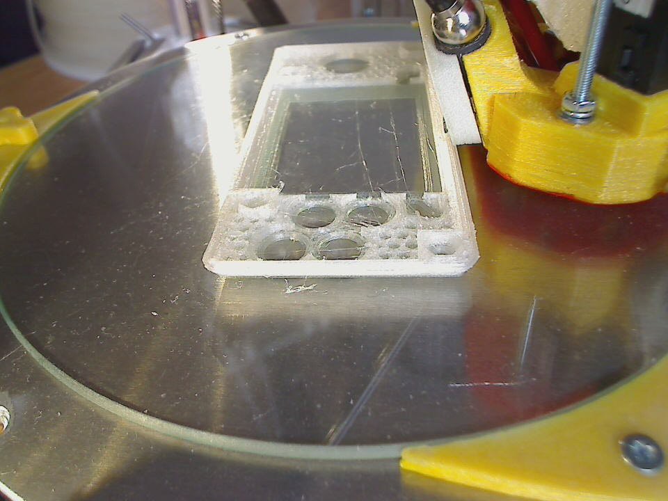
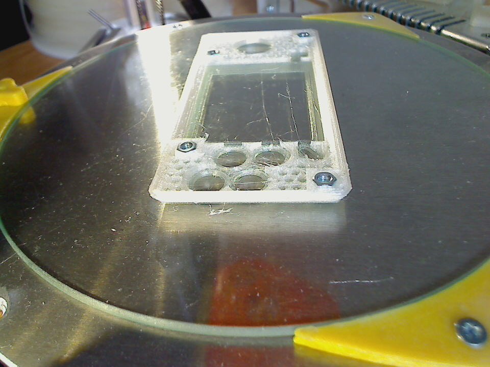
    btw: the front piece in its current form uses the pause-print-insert-M3-trapped-nuts-resume-print approach:


    STLs to print your own are on github :-)

  • and another minor mistake...

    JohSchneider04/02/2016 at 14:25 2 comments

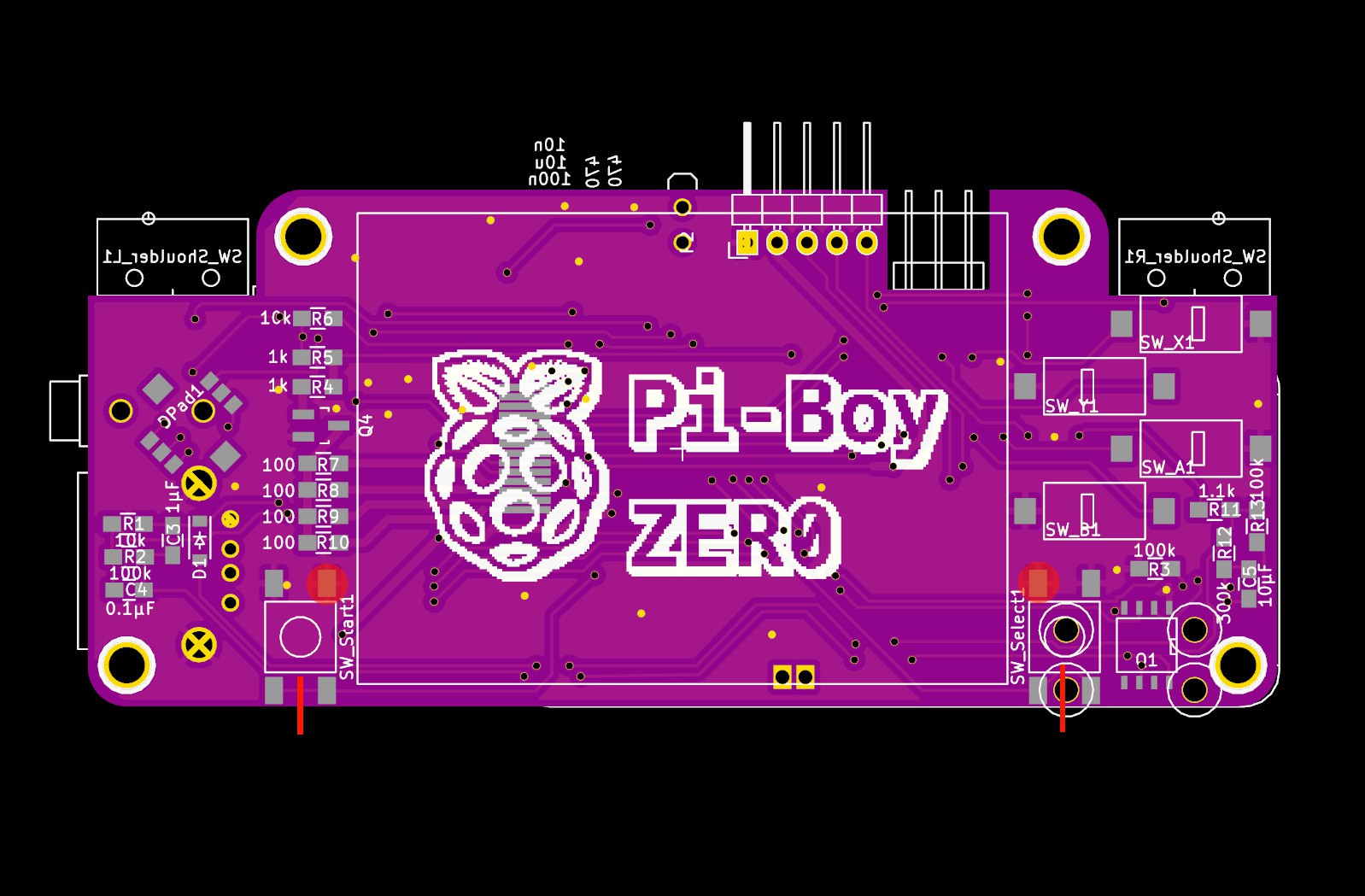
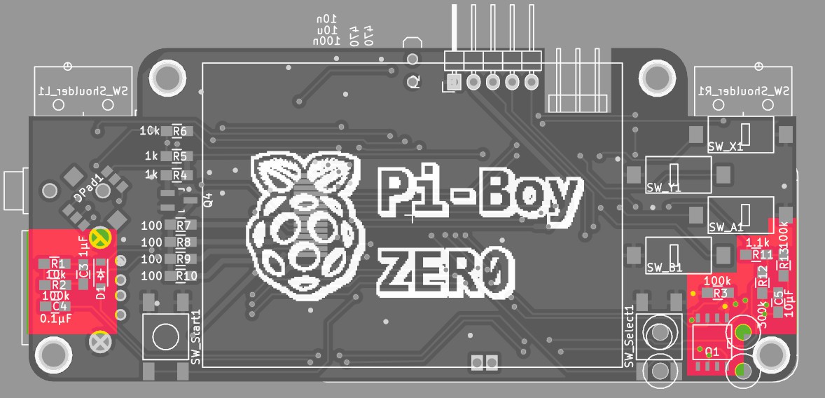
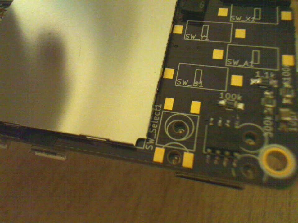
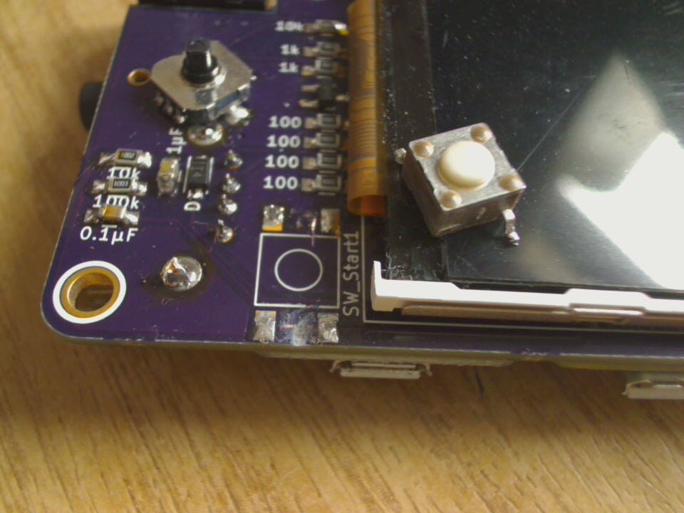
    another wrong footprint...the push buttons used for start/select group their four pins in pairs - the other way round

    ... really need to learn to double check the datasheet for all components that have more than two leads - even trivial ones like buttons :-P


    oh well - the fix was to desolder the button, cut some traces and amputate a leg >:-)

    updated the pcb layout and pushed the changes to git and osh-park


    update 2016-04-13

    for anyone who happen to have this buggy version, the fix looks like this:

    cut the start/select traces at the red lines, and do not solder the button pads marked with the circle...

  • soldering the remaining components

    JohSchneider04/02/2016 at 14:14 0 comments

    mainly buttons and the usb socket...

    the usb-socket has mounting tabs which i decided to trim down at the side close to the alps-nav switch, just in case the room is needed later on by the 3d printed that'll come ontop of it

    the omron switches chosen for ABXY have some position keys on the back, which have to be trimmed also -- which was a design decision, including holes for those would have interfered with the smd-pads on the other side

    in retrospect it would have been a bit easier to mount the tft last, since it sits close to some solder-pads... but it was still doable

  • Pi Zero PWM Audio - device tree overlay

    JohSchneider04/02/2016 at 11:03 3 comments

    the adafruit guide for pwm-audio on the pi-zero ( https://learn.adafruit.com/adding-basic-audio-ouput-to-raspberry-pi-zero/pi-zero-pwm-audio ) configures the gpio-alt functions on the fly to remap the audio-pwm pins from hidden ones to pins on the gpio-pinheader
    after reading up on

    device tree configurations and tracking down all necessary pieces, i got this this code snippet/overlay to do the same at boot-time:

    /dts-v1/;
    /plugin/;
    
    / {
      compatible = "brcm,bcm2708";
    
      fragment@0 {
        target = <&gpio>;
        __overlay__ {
          pinctrl-names = "default";
          pinctrl-0 = <&pwm_audio_pins>;
    
        pwm_audio_pins: pwm_audio_pins {
    	brcm,pins = <13 18>;   /* gpio no ('BCM' number) */
    	brcm,function = <4 2>; /* 0:in, 1:out, 2: alt5, 3: alt4, 4: alt0, 5: alt1, 6: alt2, 7: alt3 */
    	brcm,pull = <0 0>;     /* 2:up 1:down 0:none */
          };
        };
      };
     };

    this maps the left channel to pin 33 (BCM=13) and the right channel to pin 12 (BCM=18)

    compiled with:

    dtc -@ -I dts -O dtb -o pwm-audio-pi-zero-overlay.dtb pwm-audio-pi-zero-overlay.dts
    and enabled by appending this line to the /boot/config.txt:
    dtoverlay=pwm-audio-pi-zero

    helpful links:

    http://elinux.org/RPi_BCM2835_GPIOs - pins and alt functions for the pi-zeros cpu

    https://learn.adafruit.com/introducing-the-raspberry-pi-zero/audio-outputs - the other adafruit guide, touching opi-zero pwm audio

    https://www.raspberrypi.org/documentation/configuration/device-tree.md - general documentation on devicetrees on raspberry

    https://www.raspberrypi.org/documentation/configuration/pin-configuration.md

    https://www.kernel.org/doc/Documentation/devicetree/bindings/pinctrl/brcm,bcm2835-gpio.txt - documentation on the gpio pinconfig via dtoverlay

    https://github.com/fivdi/onoff/wiki/Enabling-Pullup-and-Pulldown-Resistors-on-The-Raspberry-Pi - good example of gpio config via dt-overlay

  • solder&test MK2

    JohSchneider04/01/2016 at 20:15 0 comments

    ok, again repopulating the board with the components grouped by function (the raspberry-zero and the powerboost 500 are already mounted)

    first: soft-power

    connecting the lipo battery and hitting the power button the pi boots, and pulling the gpio down powers it of :-D


    second: audio

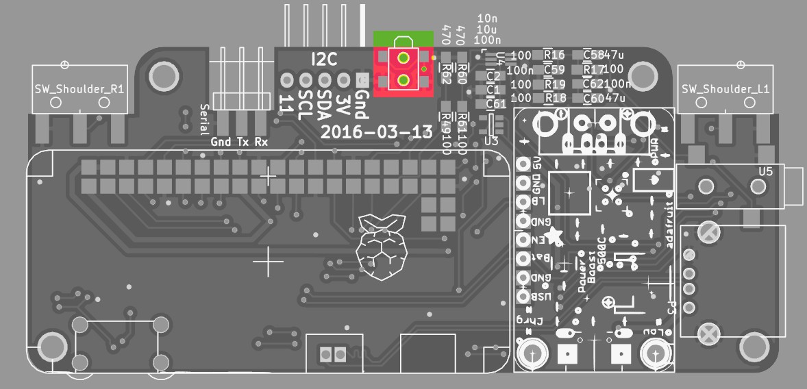
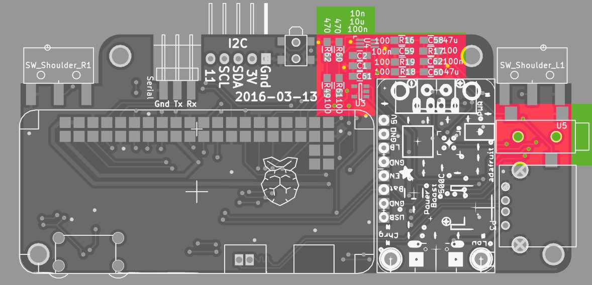
    NOTE: the components in the top right corner are left/right channel = two times the same set, but their placement got a bit mixed up = is not symmetrical... oh well, just have to follow the silkscreen :-P

    Testing the audio with a pair of headphones: works! :-)

    (when nothing is playing - eg the channels are silent - there seems to be a tiny bit of high frequency noise coming from somewhere - and sd-io is also slightly audible... i wonder if that is just due to the anaolog/pwm nature of the system or bad board design/soldering :-S )


    third: backlight and tft display:

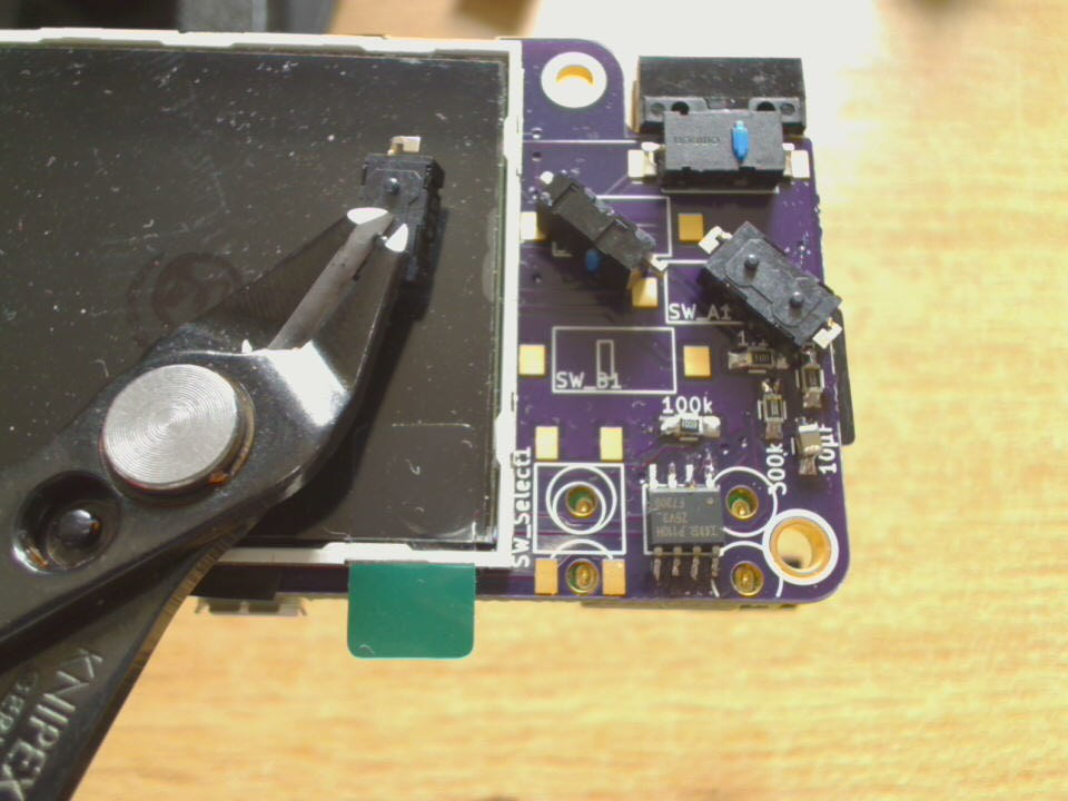
    the 2.2" display is held by a metal bracket, which in turn is glued with strips of double sided tape to the donor-pcb.

    a sharp knife makes short work of these:

    reapplied double-sided tape to the bracket and glued it to the pi-boy pcb - aligned to the right edge of the silkscreen square

    Note: are some contacts on the front-side of the pi-boy-pcb that need to be masked of with insulating tape befor glueing down the metal braket!

    transplanting the tft screen:

    * the ribbon cable of the screen was desoldered from the donor-pcb with the previously mentioned tea-candle method

    * pre-tinning the contacts on the pi-boy pcb

    * and finally re-soldering the 14 contact

    * double/tripple check the solder-joints/solder bridges since the contact pitch is ultra small :-P

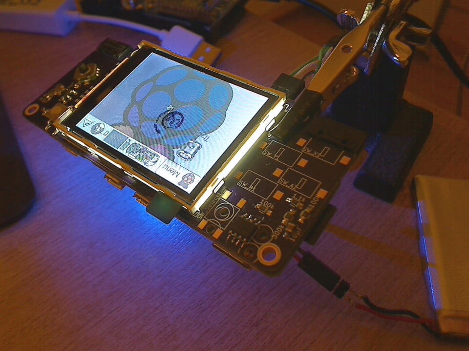
    powering the hole thing up and we have picture! :-D

    (upside down, but thats easily fixed in the config)
  • hand soldering the raspberry to the baseboard

    JohSchneider04/01/2016 at 13:54 2 comments

    similar projects that mounted the raspberry onto another pcb seem to reflow it in some way or another, with a hot-air rework station or similar tools. the same is doable with a good fine tipped soldering iron.

    these steps seemed to produce good results:

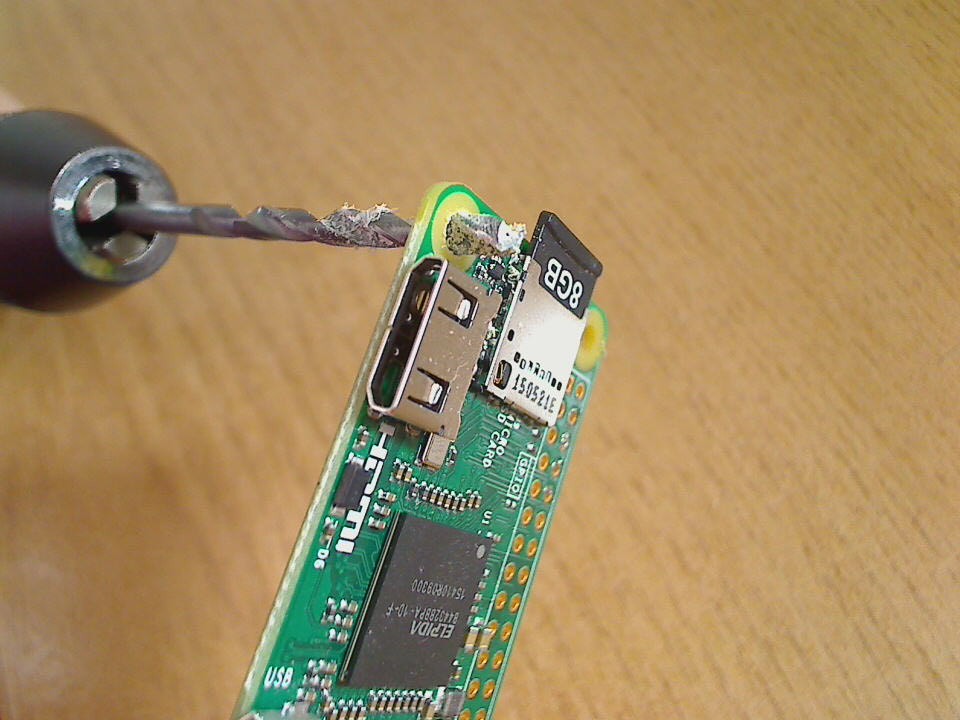
    1) widen the mounting hole near the hdmi to 3mm, which will be used as position key (and later on by a screw holding the case together) - done by hand, very carefully :-)

    2) pre-tin all the surface mount pads on the base-board with a slight (!) amount of solder

    3) use a M3 screw to get an accurate position, clamp the boards together and solder by first heating up the rim of the pin-hole, then feeding solder into it until the hole is roughly half filled. at this point it should connect with the pad below and visibly suck the solder a bit down

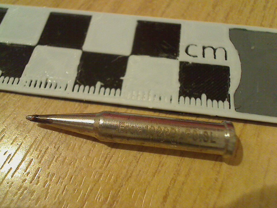
    the tip i used fit halfway through the pin-holes, which i could put into the soldered holes that seemed to have a hard time connecting to the pad below (was the case with some of the holes connected to the ground plane, since they sucked the heat away pretty fast)

  • candle-light desoldering

    JohSchneider03/31/2016 at 19:13 0 comments

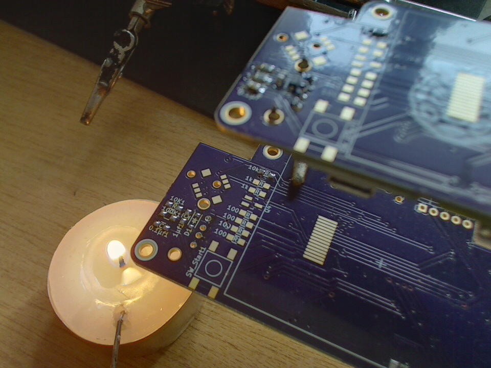
    not wanting to discard the perfectly good smd-components that are already on the Mk1 pcb a candle-light desoldering session was in order: the Mk1 pcb below - roughly 1cm above the flame of a small tea light candle - and the Mk2 above ready to receive the transplant

    moving the candle under the specific components to desolder; small tweezers in one, the solder iron in the other hand - worked like a charm :-)

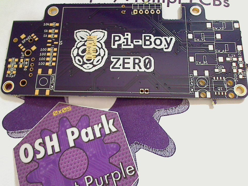
  • PCBs Mk2 arrived :-)

    JohSchneider03/31/2016 at 13:57 0 comments

    things of beauty :-D

    time to desolder the Mk1 and populate the Mk2...

View all 31 project logs

View all instructions

Enjoy this project?

Share

Discussions

David wrote 04/09/2016 at 15:00 point

We have a similar project on Hackaday. Would you be interested in some collaboration? I think both our projects could benefit from it. [@Jean-André Santoni] and I hang out at https://discord.gg/0y3hRkVsItoaCAR1.

  Are you sure? yes | no

arnaud.durand wrote 04/11/2016 at 20:51 point

@David Perrenoud: I just discovered your project; I'm very impressed that you use RGB666 to drive the screen. Bravo! I was planning to contribute to the PiGrrl-Zero with an alternative version featuring a Sharp LS035Y8DX04A display (3.5", IPS) as I was excited with the 60 FPS promise of http://blog.reasonablycorrect.com/raw-dpi-raspberry-pi/. I didn't know this interface was available on smaller displays.

  Are you sure? yes | no

JohSchneider wrote 04/13/2016 at 13:56 point

from my experience the 60fps are nice to have, but having less doesn't kill the fun in any way - having buttons with a good response/"feel" is IMO more important :P

@arnaud.durand: i havn't seen any screens that size that have the parallel display and are readily available so far either (another plus for the adafruit screen :-)

  Are you sure? yes | no

David wrote 05/07/2016 at 16:28 point

@JohSchneider Are you still interested? There are around 100 people on the Gamegirl Discord chat and I would be very glad if you could advise us on the PWM/PCM audio. We can help you with the buttons in exchange.

  Are you sure? yes | no

JohSchneider wrote 04/07/2016 at 19:04 point

@david: if i read the datasheat of the display correctly (https://cdn-shop.adafruit.com/datasheets/TM022HDH26_V1.0.pdf) only the serial/spi bus is broken out - not the parallel on :-/

in a previous project i used a similar pi-tft hat with the notro-fbtft+fbcp setup at roughly 20fps - which worked well for SNES/GBA/...-games :-)

  Are you sure? yes | no

david wrote 04/07/2016 at 19:10 point

Does it really work well? I recall GBA being 60 or 30fps

  Are you sure? yes | no

JohSchneider wrote 04/08/2016 at 11:03 point

good enough for me at least :-)

dunno about the original GBA...

  Are you sure? yes | no

Jasper parker wrote 04/02/2016 at 14:51 point

ok no worries ill contact my supplier and request a few of these PCB boards slip into my usual production :)

... Wondering why Pi zero is so expensive in Australia !

  Are you sure? yes | no

Jasper parker wrote 04/02/2016 at 11:15 point

fantastic 

Will you be doing a production run of the boards and offering them for sale ? 

  Are you sure? yes | no

JohSchneider wrote 04/02/2016 at 14:02 point

so far i don't plan to...

  Are you sure? yes | no

Jasper parker wrote 04/02/2016 at 06:10 point

Will the enclosure files be available for 3D printing ? 

  Are you sure? yes | no

JohSchneider wrote 04/02/2016 at 10:48 point

yes, as soon as i'm done printing and refining them i'll add them to the git repository. so far their still in the draft stage since i'm still busy building the hardware :-P

  Are you sure? yes | no

JohSchneider wrote 04/01/2016 at 19:27 point

@arnaud.durand : just had a look at those two dpads, they are tiny! :-) but probably to tiny, the pads are 2mm diameter and diagonaly only a few milimeter apart - IMO not ideal add a 3d-printed dpad-cross above it...

@K.C. Lee: how big is your d-pad solution, and what buttons does it use (btw: had something similar in mind to protect the screen from scratches - not a thin piece of packaging plastic though, but with a piece of acrylic)

  Are you sure? yes | no

K.C. Lee wrote 04/01/2016 at 22:10 point

I made my d-pad out of 5 individual tactile momentary switches.  Sorry it was a one off DIY hack not designed for a production.

I had the side activated one, but trimmed/hack it to be a vertical mounted one.  Not sure about the exact model as I got a bag of it.  It is probably Omron brand one based on the shape, colour and the style.  

http://www.digikey.com/product-detail/en/omron-electronics-inc-emc-div/B3F-3152/SW410-ND/31741

The most important thing is the capture cap and the really sloppy mechanical - that allow it to tilt slightly to the sides. Here are the others that are probably easier to use:

http://www.digikey.com/product-search/en/switches/tactile-switches/1114206?k=&v=39&FV=fff40011,fff8005e,8840017&mnonly=0&newproducts=0&ColumnSort=0&page=1&quantity=0&ptm=0&fid=0&pageSize=500

The spring is from my junk box.  It is very weak, but just the right strength to take off the slack so the diamond doesn't wobble.  I measured about 60g of compression force with my digital scale at its final resting position.

I laid the switch on a 0.4" grid.  The diamond is 0.9"x0.9" square, so 1.27" corner to corner.  It is slightly bigger than the one on the original Xbox controller, but you can trim it back to where it hits the buttons.  

Because it is built with tactile switches, there is a very notable click and feel to it not the mushy silicon dome.

  Are you sure? yes | no

JohSchneider wrote 04/02/2016 at 03:35 point

thnx for the input!

0.9"square is more space than i have on the pcb - thats probably the only downside to the all-tactile switch design: the size can't be cut down much because the individual switches need a minimum of clearance and such... still good design idea (especially the spring)

  Are you sure? yes | no

K.C. Lee wrote 04/01/2016 at 22:21 point

BTW take a look at the cursor keys of the PC8201.  I got one and that diamond key is very good for playing games.  You just have to make those key caps for the individual momentary switches.

https://deskthority.net/wiki/NEC_PC-8201

  Are you sure? yes | no

JohSchneider wrote 04/02/2016 at 03:32 point

that's an idea for the keycap - would be easy enough to reproduce with a 3d printer. will keep it in mind for the next project that needs a d-pad :-)

  Are you sure? yes | no

david wrote 03/31/2016 at 20:30 point

Hey! Nicee work! I was planning on doing something similar, I miss creating videogames :) How do you plan driving the screen? The bandwidth to drive the screen is 320*240*60*16 = 74Mbps, this is a 75Mhz SPI clock. Is that within the contraints? I dont think so... I looked at the ILI9340 datasheet and its possible to use a parallel 8 or 16 bit wide, which could reduce theclock down to 5MHz, and reduce the CPU usage. Can you comment on that? BTW only bigger screens like 2.8'' have adafruit boards available for soldering. Maybe using an adafruit screen without the PCB board (just add your connector to the PCB)  could help you a lot.

  Are you sure? yes | no

JohSchneider wrote 04/01/2016 at 18:21 point

thnx :-)

the screen i picked will run via spi but not at 60fps, more like 20 because of the bandwidth constraints, theres a guide linked in the pitft site - basically its notro's fbtft kernel module plus a daemon that copies from fb0 to fb1 (yes... not overly performant, but works well enough for these small resolutions and emulation-station)

see components listed above for a link to the adafruit board with the target tft

  Are you sure? yes | no

david wrote 04/02/2016 at 12:26 point

And don't you think it's gonna be too low? I mean, 20fps is gonna produce many glitches in most games. That screen shot support parallen 8/16 bit mode, does the connect break out those pins for you? We can always play a bit of kernel driver hacking :)

  Are you sure? yes | no

max wrote 03/28/2016 at 08:16 point

Why not using a directional cross for the d-pad? The Alps solution is good and durable, but maybe not so good to act as d-pad on a console. In gaming hystory the best were GBA, NDS, PSP and also Xperia Play was great in precision. 

So far the project is awesome, can't wait to build mine. What about putting Wi-Fi capability as well? This could lead to multiplayer gaming in emus, easy file transfer, ota updates and lot of other good things..

  Are you sure? yes | no

JohSchneider wrote 03/31/2016 at 18:55 point

did you have a specific component in mind as alternative? AFAIK most console controllers are build with rubber-dome/chiclet key type d-pads, which would eat up quite a lot of space, and are not easy to source (short of butchering a console controller)

for wifi: there is an usb-A connector on-board :-)

  Are you sure? yes | no

arnaud.durand wrote 03/31/2016 at 22:21 point

If the Alps turns out to be a bad solution (I don't have any experience with these) it seems there are tons of options:

http://www.digikey.com/product-search/en/switches/navigation-switches-joystick/1114837

I wonder if pads like EVQ-Q3AA15 or JS1300AQ would be usable. In the worst case, the PSP thumb slide joystick (analog) is easily sourced and is available from Adafruit and SparkFun.

Btw; I love your project!

  Are you sure? yes | no

ford.anthonyj wrote 03/25/2016 at 00:33 point

Out of curiosity, why did you choose PWM for the audio over using an I2C DAC? Cost? Or simplicity? 

Good luck with the project. I'm waiting for the final revision, then I'm gonna make one.

  Are you sure? yes | no

JohSchneider wrote 03/25/2016 at 03:11 point

i actually looked into the I2S dac option (first few logs) and decided against it - main reasons where a mix of saving space (on the pcb and gpios), keep it simple (to solder) and the fact that my intended usage-scenario will not need highest quality audio (if any at all)

looking forward to see pictures of your make :-)

  Are you sure? yes | no

Vlad Conut wrote 03/22/2016 at 10:30 point

Interesting project i don't usually play games but i could see myself using this on my daily commute - on question though given that you already made your own pcb why not include the DC/DC onto the board instead of using a premade one - pretty sure will save some board space and be more cheaper :)

Good luck with your project and congrats for winning the pi zero contest 

  Are you sure? yes | no

JohSchneider wrote 03/22/2016 at 13:59 point

thnx :-)

yeah, i thought about integrating the dc converter (see the first few logs)... but the common chips used in those (and lipo chargers) are not of the hand-solder-friendly kind... so i opted for the of-the-shelf solution

  Are you sure? yes | no

Andrew Wipf wrote 03/22/2016 at 03:17 point

I literally told my friend this afternoon we should start on something like this. Cannot wait to see a working prototype and pull the trigger on 2-3 sets of parts!

  Are you sure? yes | no

Martin wrote 03/22/2016 at 01:29 point

TAKE ALL MY MONEY!

This needs to be a thing, I badly want an eNcade case for a Pi but they are so far undelivered even to the kickstarter backers...

  Are you sure? yes | no

8bit-bunny wrote 03/08/2016 at 20:14 point

when will the orders open? i want one! :D 

also good job on doing this project, i litterally had the same project idea just now!

  Are you sure? yes | no

JohSchneider wrote 03/10/2016 at 14:49 point

orders? we're here on DIY-heaven, not shit-starter ;-)

TBH so far i'm doing this project for the mere fun of it, and didn't waste much thought about commercializing it... might be willing to part with the extra PCBs i get from the fab though

  Are you sure? yes | no

8bit-bunny wrote 03/10/2016 at 15:35 point

i was joking on the orders to be honest, though i would love to have a blank pcb for myself to start soldering. keep it up! :D

  Are you sure? yes | no

Mark Kuhlmann wrote 03/10/2016 at 17:06 point

My Pi Zero is sitting lonely on my desk awaiting the next gen of the PCB's haha.

  Are you sure? yes | no

chris.arney wrote 03/08/2016 at 02:00 point

Awesome project! I was just googling for a gameboy micro form factor emulator! (Seriously) I just ordered a screen, but haven't been able to get my hands on a zero yet. Have you thought about adding a backlight control? I was thinking about using a 555 and potentiometer to add a PWM for a backlight control. The other thought I had was to add an internal speaker with a headphone jack that would switch to headphones when inserted. A volume control would be nice also. Thanks for sharing your work. I'll be frequenting your project, hoping to get time to build my own!

  Are you sure? yes | no

JohSchneider wrote 03/08/2016 at 15:29 point

glad you like it!

yes i was planning on hooking a gpio pin to the backlight and do software pwm (already in the schematic/pcb) - untested so far :P

the two pwm channels on the raspberry are intended to put audio on an audiojack - i'm no fan of speakers, so i opted for headphones only solution

  Are you sure? yes | no

chris.arney wrote 03/08/2016 at 18:10 point

I'm not super familiar with the RPi products, but from the adafruit page on the LCD, they mention that the Pi doesn't have enough PWM channels to do both audio and backlight control. That's what sent me looking for a stand-alone PWM circuit.

https://learn.adafruit.com/adafruit-2-2-pitft-hat-320-240-primary-display-for-raspberry-pi/backlight-control 

I understand the headphone only direction. I wasn't sure how much space there was for a speaker anyway. Whenever (if) I get around to building my own, I'll look into adding a speaker.

edit: I just re-read and you're doing a SW PWM.

  Are you sure? yes | no

AVR wrote 03/01/2016 at 18:47 point

someone beat me too it lol (thought about doing the same thing), congrats on being one of the picks, I'll have to check out your PCB design files :)

  Are you sure? yes | no

JohSchneider wrote 03/02/2016 at 13:25 point

thnx - in case you do and spot anything, or have any suggestions, let me know :-)

  Are you sure? yes | no

Mark Kuhlmann wrote 02/26/2016 at 02:36 point

Going to wait until the bugs are worked out but I definetly want to build one of these.

  Are you sure? yes | no

JohSchneider wrote 03/02/2016 at 13:26 point

good idea - when you come to building one, post some pictures :-)

  Are you sure? yes | no

Mark Norelus wrote 02/26/2016 at 00:24 point

Awesome project :D Working on something similar. 

  Are you sure? yes | no

JohSchneider wrote 02/26/2016 at 01:24 point

cool! anything out on the webs, or is your project still in the "early phase"? :-)

  Are you sure? yes | no

Mark Norelus wrote 02/26/2016 at 16:04 point

Soon! Somewhat in the early phase but fully planed and started.  

Would be great  to get your input once I start posting information about my project. 

  Are you sure? yes | no

Jeremy g. wrote 02/18/2016 at 21:41 point

Definitely going to build one of these! good job.

  Are you sure? yes | no

JohSchneider wrote 02/19/2016 at 18:05 point

please do! - and post some pictures :-D

(might want to wait till i completed one though and worked out the kinks)

  Are you sure? yes | no

Craig Hissett wrote 02/16/2016 at 16:46 point

I would love one of these!

  Are you sure? yes | no

JohSchneider wrote 02/19/2016 at 18:02 point

:-D

  Are you sure? yes | no

LLeny wrote 04/04/2016 at 08:51 point

awesome project, looking forward to the first working prototype.

  Are you sure? yes | no

Alexander wrote 02/13/2016 at 15:40 point

Consider this form factor ideal for gaming.

  Are you sure? yes | no

JohSchneider wrote 02/14/2016 at 17:38 point

i definetly hope that it'll turn out that way :-)

  Are you sure? yes | no

Does this project spark your interest?

Become a member to follow this project and never miss any updates