JohSchneider
-
pcb on OSH-Park
02/15/2016 at 19:10 • 0 comments -
schematics up on github
02/15/2016 at 19:05 • 0 commentswaiting for the pcb to be fabbed and the ordered parts to arrive :-D
meanwhile: just created a repo on github with the current schematics here: https://github.com/JohSchneider/piboy-zero
-
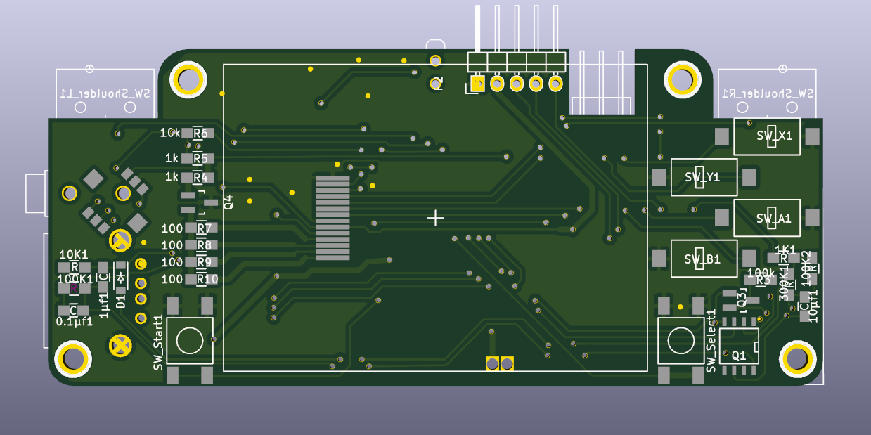
unraveling traces...
02/13/2016 at 03:56 • 0 commentsfirst version of the schematic and layout for the carrier-pcb - kicad does a nice job rendering it :-)
front side:
![]()
back side:
![]()
-
adding the tft
02/10/2016 at 18:07 • 0 commentsaddingthe TM022HDH26 spi display and a raspberry to the mixof battery + powerboost + softpower-circuit
the breakoutboard is a cheapish chinese import, with a slightly different wiring for the backlight - the important part: the display is the same as in adafruits 2.2" pitft hat (and their 2.2" spi display breakout).
hence it is easy to get it up and running following these instructions:
![]()
-
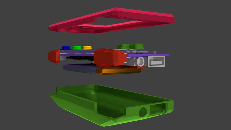
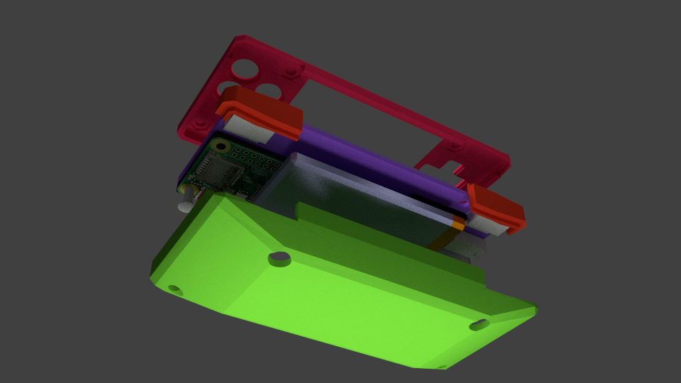
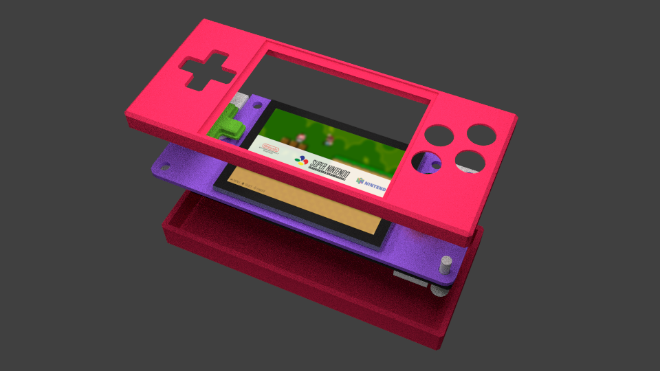
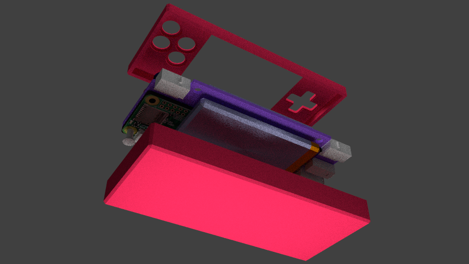
case refinement
02/09/2016 at 20:17 • 0 commentsthis time more internal components (on the raspberry and the powerboost pcb) have been taken into consideration while positioning the battery and resizing the enclosure - the new boundingbox measures 106mm x 48.3mm x 21mm
also the (preliminary?) position/cutouts for the usb and headphone jack have been included.
and lastly: shoulder buttons!
![]()
![]()
![]()
-
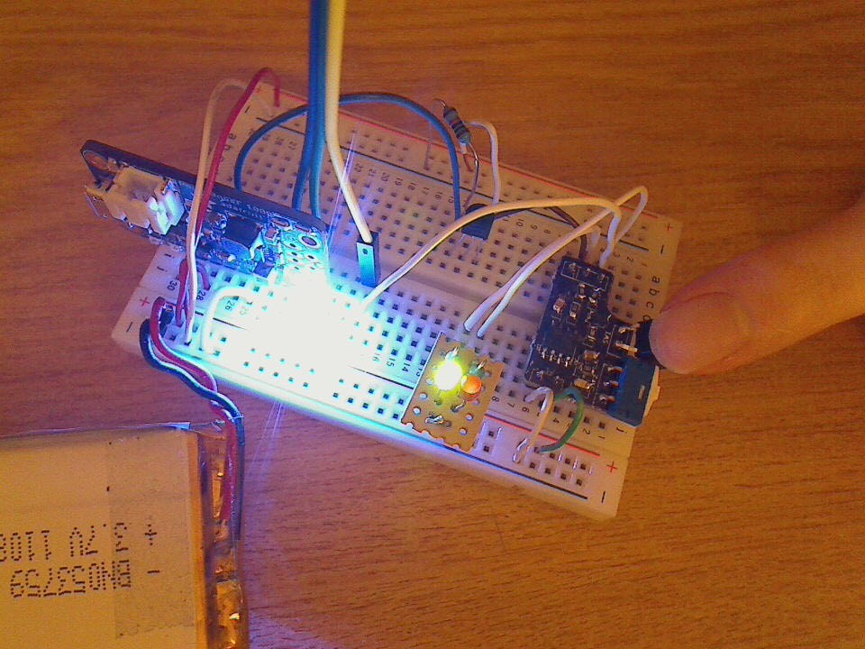
powerboost + softpower prototyping
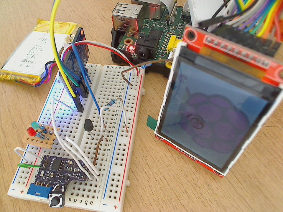
02/09/2016 at 16:56 • 0 commentsbreadboard prototyping of the powerboost + battery + soft-power-button circuitry
off (powerboost enable pulled low)
![]()
on touch of the push-button -> power on!
![]()
the three wires running to the top and out the image will be connected to the raspberry pi, and give it +5V, Gnd and a control/sense wire to the soft-power circuit - that way it will be able so detect further button pushes shutdown properly and cut the power by pulling the control-wire low
further description of the soft-power circuit is available here:
-
first draft of an enclosure
02/06/2016 at 19:27 • 0 commentsugly&boring version of a 3d-printable case for the whole assembly :-P
after moving components around a bit, and adding a 1200mAh battery...
the current bounding-box measures: 104mm x 46mm x 17mm
(this *will* change, since currently the various components on the pcbs are not factored in)
![]()
![]()
-
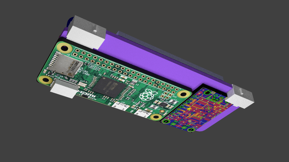
module on module
02/04/2016 at 05:05 • 0 commentsafter studying the schematics, board-layouts and parts-lists of the different adafruit powerboosts it became clear that keeping the whole project hand-solderable would be tough - considering that the powerboosts are build around a boost-converter (and sometimes a lipo-charger) that only comes in a QFN-package - which seems like too much of a hassle to solder without access to a reflow setup :-(
so plan-B might be to integrate the circuit as an as-is module, with (wire-)bridges from the carrier-pcb to the powerboost-pcb?
![]()
like this maybe?
-
feature creep 2
02/03/2016 at 20:41 • 0 commentslet there be sound!
https://learn.adafruit.com/introducing-the-raspberry-pi-zero/audio-outputs - either the simple variant with few resistors or the raspberry-B+ version with buffer-IC
an I2S-DAC like variant is most likely overkill.. like the
https://shop.pimoroni.com/products/phat-dac ( https://www.adafruit.com/product/3016 IC=PCM5102A )
or similar https://polyvection.com/shop/plaindac/ (IC=PCM5142)
-
feature-creep 1
02/03/2016 at 11:01 • 0 commentsa dedicated button to power the whole thing on and off (in an orderly fashion) might be nice - something like this:
PiBoy-Zero
yet another portable console! ;-) roughly the size of a gameboy micro, with a 2.2" display