Close
0%
0%

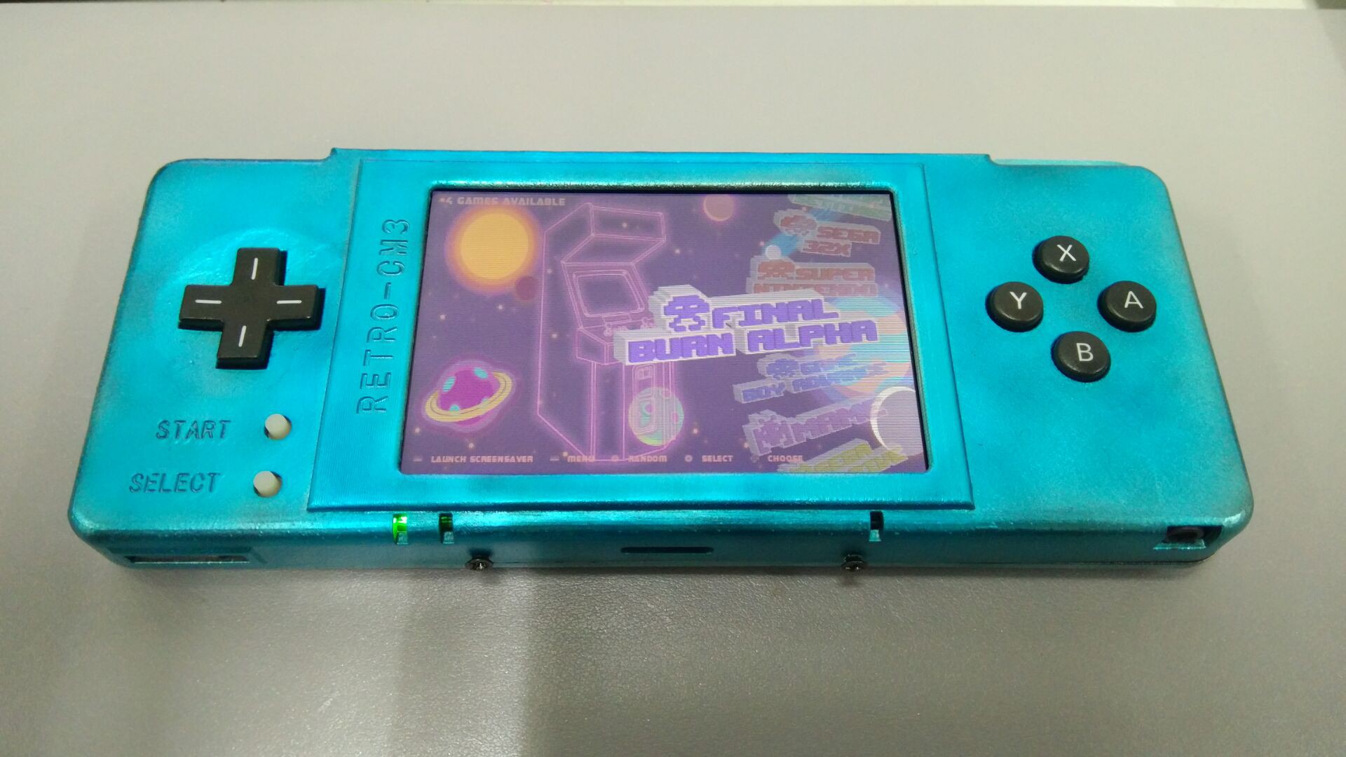
RETRO-CM3: A POWERFUL RETROPIE HANDLED GAME CONSOL

In this project, I will use the RaspberryPi Compute Module 3 and a DPI interface LCD to build a ultimate RetroPie game console.

Similar projects worth following
This project is inspired by the adafruit's PiGRRL Zero and Wermy's original Gameboy Zero build. Those RetroPie based game console use the raspberry pi zero(W) as their core. BUT, after I have built several the Pi Zero Consoles, two main problems were found.
1) The Raspberry Pi Zero (W) has only single core Cortex-A7 and 512MB ram, which is OK for NES/SNES/GB kind of things. However, when I tried to run the PS/N64 Emus, the experience was quite unacceptable. Even the some of the GBA games can not run smoothly (Some audio lag);
2)Most of the game console builds use SPI or TV-out as the display interface. The SPI display will need the CPU to help with the frame buffer driver which will make the game experience worse and the fps is also limited by the speed of SPI clock. And the display quality of TV-out is just not good enough.
In this project, I will use the RaspberryPi Compute Module 3 and a DPI interface LCD to build a ultimate RetroPie game console.

I posted a instructable here earlier and think you guys may like to see it here. So I copy most of the content here, hope you guys enjoy it.

As a whole, this project is to try my best to design a ultimate RetroPie based handled game console. Several changes were made to traditional ones. 

First, I used a DPI interface to connect the Pi to the LCD module. As DPI is supported by hardware, this interface will not bother the CPU to do any calculation. Also, DPI interface supports higher resolution, higher frame rate and better display than the SPI or TV-out. In my prototype, I used a 3.2 inch, 800*480 LCD module which is far more from enough.

Second, I used the Raspberry Pi compute module 3 as the core board. Traditional handled game console design either use the Pi zero or the Pi 3B. The Pi 3B will certainly make the console thick and the Pi Zero is just not powerful enough to run all the emulators smoothly.

However, the CM3L has both the size of Pi zero and the power of Pi 3B.

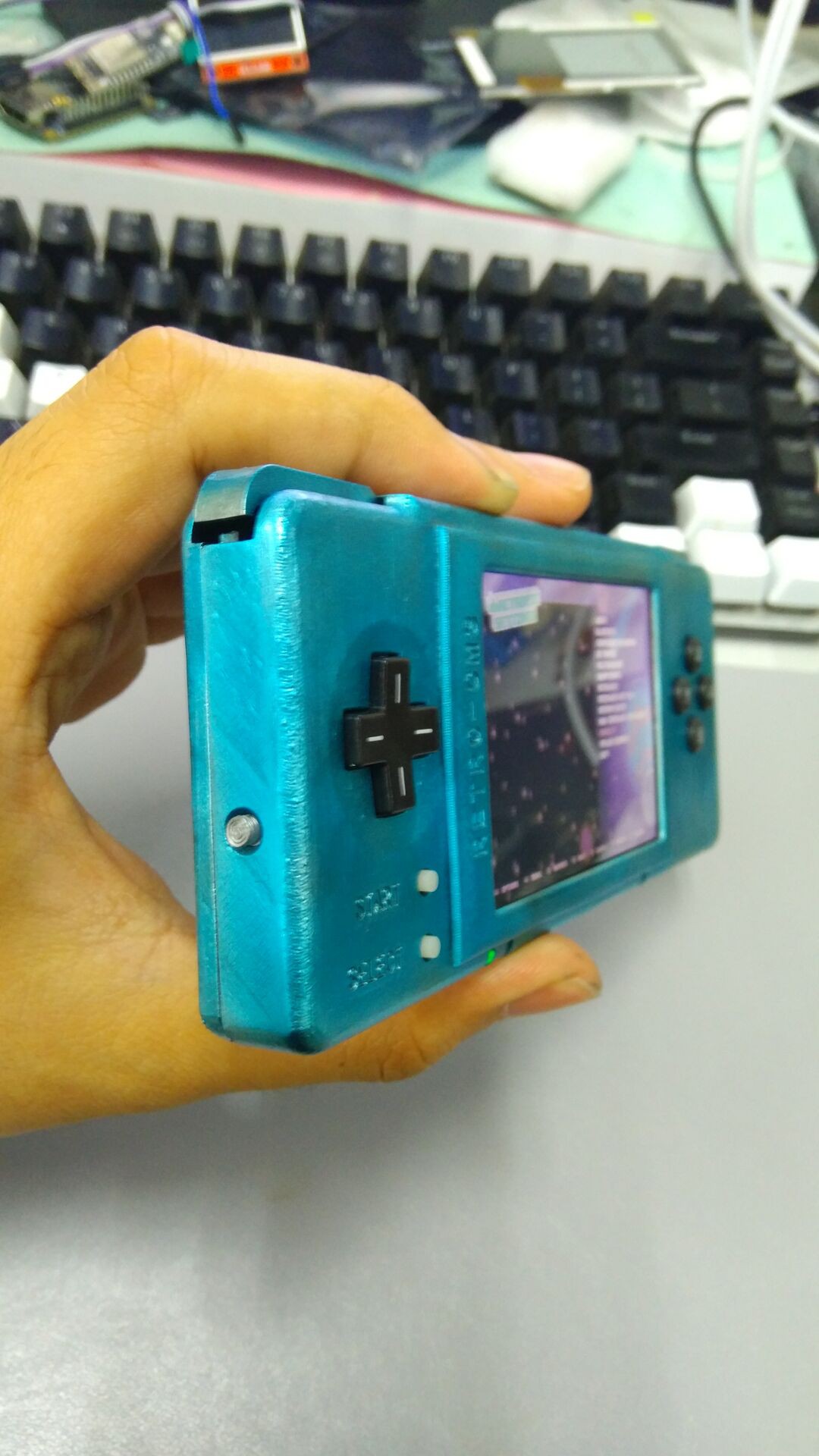
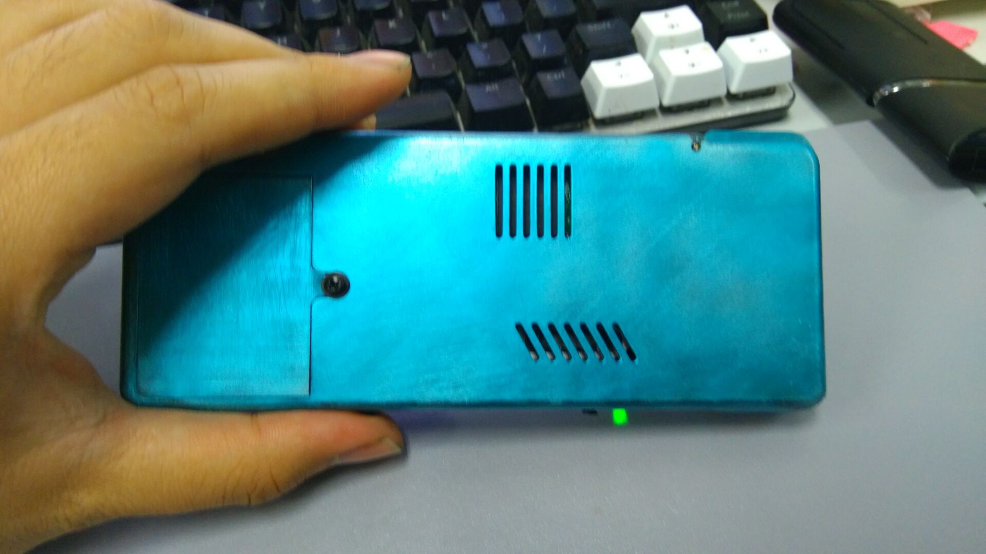
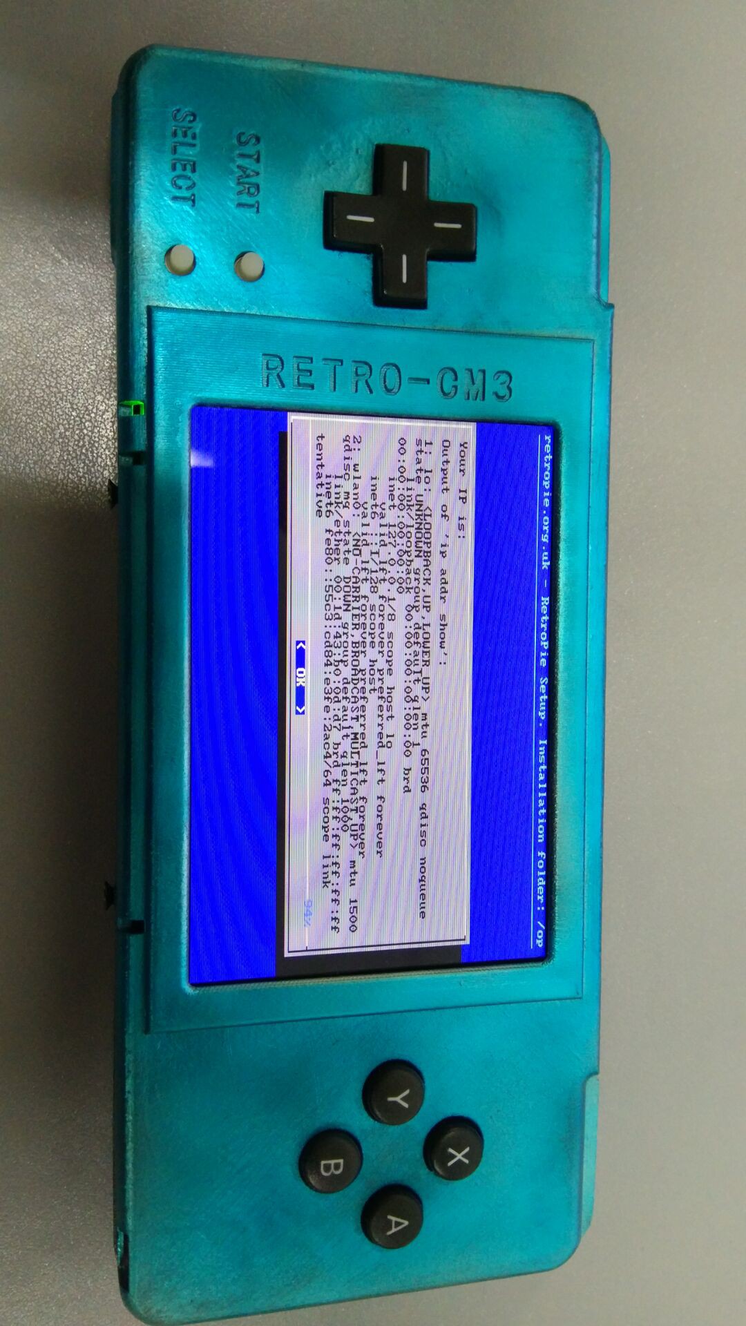
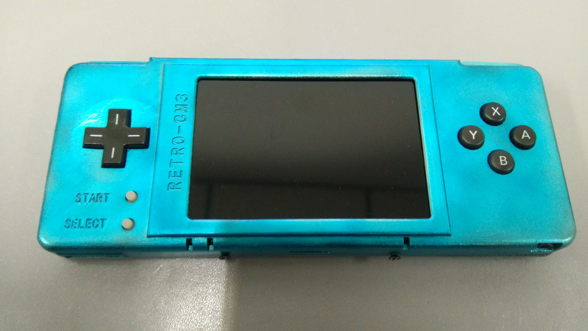
The finished game console is just 152x64x18mm with the capability to install up to 2000mAh battery. The total built costs about $65, including a custom PCB, all the components, a 16GB TF card and a RaspberryPi compute module 3 Lite (Costs may varies quite a lot according to the price of making a PCB and the price of the components). As I already have a 3D printer, the case costs me only 64g PLA filament.

During my test, the console is able to run the Ps/N64 emulators at about max frame rate for most time. And the gaming experience of GBA and NEOGEO is much better than my Pi zero try out. No significant video or audio lag can be noticed during all the gaming. 
Retropie-CM3-gerber.zip

Gerber files of this project

Zip Archive - 189.85 kB - 04/08/2018 at 13:29

Download

Retropie-CM3-PCB.zip

The PCBDOC

Zip Archive - 1.47 MB - 03/19/2018 at 03:57

Download

Retropie-CM3.pdf

The Schematic

Adobe Portable Document Format - 471.47 kB - 03/19/2018 at 03:57

Preview

Retropie-CM3-STM32.zip

The STM32 source to simulate the keypad.

Zip Archive - 257.05 kB - 03/19/2018 at 03:57

Download

Retropie-STL.zip

The STL files for the 3D print case.

Zip Archive - 207.18 kB - 03/19/2018 at 03:57

Download

View all 8 files

  • 1 × RaspberryPi Compute Module 3 Lite Used as the core of this game console. Buy it from the shop where you got your RaspberryPi 3B or try it on ebay
  • 1 × 3.2 inch LCD module with DPI MAKE SURE you got a RGB/DPI interface LCD module because it is a MUST to build this console. I got my LCD from a local e-shop and same module can be found in alibaba. If you buy an alternative LCD module, DO ASK the provider to send you the detailed parameter and initialization code. It is also a wise choice to buy the corresponding connectors from the same shop as there are so many different type of connectors.
  • 12 × ALPS SKPDACD010 Tact switch with 1.75 mm travel. Search it on your local electronic component shop.
  • 5 × Some other keys Use any other tact keys you can get for the START/SELECT/VOL+/VOL- buttons.
  • 1 × Speaker Any 8 ohm, 0.5-1.5 W speaker.

View all 10 components

View all 2 project logs

  • 1
    Using The Compute Module 3

    The Raspberry Pi Compute Module 3 is a very powerful core board for prototyping some interest gadgets. Detailed introduction can be found here. And some useful information can be found here.

    The module uses a DDR2 SODIMM type connector, which is a slightly harder to use. In addition all the GPIO pins of the BCM2837 core BANK1 and BANK0 are lead out.

    To start using the compute module, we need to provide several different voltages: 1.8V, 3.3V, 2.5V and 5.0V. Among them, 1.8V and 3.3V are used to power some peripherals which need about 350mA each. The 2.5V power line drives the TV-out DAC and it can be tied to 3.3V as we do not need TV-out feature. The 5.0V should be connected to the VBAT pins and it powers the Core. The VBAT input accepts voltages range from 2.5V to 5.0V and just make sure the power supply can outputs up to 3.5W. VCCIO pins (GPIO_XX-XX_VREF) can be connected to 3.3V as we use a 3.3V CMOS level. The SDX_VREF pin should also be connected to 3.3V.

    All the HDMI, DSI, CAM pins are not used here, just leave them float. Remember to tie the EMMC_DISABLE_N pin to 3.3V as we will use a TF card as the hard drive instead of the USB boot feature.

    The Pi need to know what is function of each GPIO. Here I provide some files, put "dt-blob.bin", "bcm2710-rpi-cm3.dtb" and "config.txt" in the boot folder of a newly flashed TF card. The put the "dcdpi.dtbo" in the /boot/overlay folder. The dt-blob.bin defines the default function of each GPIO. I change the GPIO14/15 to normal GPIO and move the UART0 function to GPIO32/33 as we need GPIO14/15 to interface with the LCD module. I also tell the Pi to use GPIO40/41 as pwm function and make them to be the right and left audio output. The dcdpi.dtbo is a device-tree overlay file and it tells the Pi that we will use GPIO0-25 as DPI function. Finally, we write "dtoverly=dcdpi" to aware the Pi to load the overlay file we provided.

  • 2
    Interfacing the LCD Module

    As different DPI/RGB interface LCD module may be used in this console, here we take the module used in my own build as example. And if you chose a different one, check the pin definition of your module and just make the connections according to the pin names as showed in the example.

    There are two interfaces on the LCD module: an SPI and a DPI. The SPI is used to configure the initial settings of the LCD driver IC and we can connect them to any unused GPIO. Only connect the Reset, CS, MOSI(SDA/SDI) and SCLK(SCL) pins, the MISO(SDO) pin is not used. To initialize the LCD driver, here we use the BCM2835 C Library to drive the GPIOs and outputs a certain initialize sequence provided by the module supplier. The source file can be found at the end.

    Install the BCM2835 C Library on another Raspberry Pi 3 according to the instructions here. Then use the command "gcc -o lcd_init lcd_init.c -lbcm2835" to compile the source file. Then add a new line in the /etc/rc.local file before "exit 0": "/home/pi/lcd_init"(assume you have put the compiled application under /home/pi folder). It should be emphasis that the source file is only used for the certain module I used and for a different LCD module, just ask the supplier for a initialize sequence and modify the source file accordingly. This process is quite tricky because at this point nothing can be seen from the screen, that's why I strongly suggest you do this on a RPI-CMIO board as it leads out all the GPIOs so you can debug it with uart or wlan.

    The following part is easy, just connect the left pins of the LCD module according to here. Depends on what kind of LCD module you have got, chose the RGB mode wisely. For me, here I chose the DPI_OUTPUT_FORMAT_18BIT_666_CFG2(mode 6). Alter the "dpi_output_format=0x078206" line according to your choice. And if your LCD module uses a different resolution, adjust the "hdmi_timings=480 0 41 60 20 800 0 5 10 10 0 0 0 60 0 32000000" refering to the file here.

    If all the settings are correct, on the next boot up of your Pi, you should see the display on the screen after a 30-40s black(from power to system loads your SPI initialization script).

  • 3
    The Key Pad and Audio

    A game console needs keys and buttons. Here we need 10 ALPS SKPDACD010 switches as the up/down/right/left, LR and A/B/X/Y buttons. And normal 6x6 surface mount keys are used for other buttons like start/select and volume-up/down.

    There are two ways to interface the buttons with the Raspberry Pi. One way is connecting the buttons directly to the GPIOs on the Pi and another way is connecting the buttons to an MCU and interface with the Pi through USB HID protocol. Here I chose the second one, because we need an MCU to deal with the power on sequence anyway and it is safer to keep the Pi away from human touch.

    So, connect the keys to the STM32F103C8T6 and then connect the MCU to the Pi with USB. An example of the MCU program can be found at the end. Alter the pin definitions in hw_config.c and compile it with the MCU's USB library found here. Or you can just download the hex file directly to the MCU as long as you share the same pin definitions in the schematic at the end.

    As for the audio outputs, the official schematic of the Raspberry Pi 3 B gives a good way of filtering the pwm wave and the same circuit should work perfectly here. One thing that should be point out is that remember to add the "audio_pwm_mode=2" line at the end of config.txt in order to lower the noise of the audio output.

    In order to drive the speaker, a speaker driver is needed. Here I chose the TDA2822 and the circuit is the official BTL circuit. Note that the phone jack PJ-327 has a auto detach pin on the right output. When there is no headphone plugged in, the pin 3 is connected to the right channel. And as soon as the headphone is plugged in, this pin is detached from the right channel. This pin can be used as the speaker input pin and the speaker will mute when headphone is plugged in.

View all 6 instructions

Enjoy this project?

Share

Discussions

bademux wrote 10/14/2019 at 13:22 point

Great Project!

Is hdmi output planned? Looks like it just about populating appropriate pins (and making switch).
HDMI along with usb is quite nice feature to play with friends.

  Are you sure? yes | no

pjy9105 wrote 04/11/2019 at 01:29 point

Hello.

I'm interested in Retro-CM3.

and I want to get flashable image file from README.md in (https://github.com/Dean-Chu/Retro-CM3), but I can't download the file in this link.

Could I get the image file?? You can give me another link or email me.

My email is pjy91055@gmail.com

Thank you :)

  Are you sure? yes | no

bademux wrote 10/14/2019 at 13:25 point

Try "Alternative link:" it work for me

  Are you sure? yes | no

Richard wrote 08/11/2018 at 03:01 point

Do you have a BOM file? Where did you get your PCB made and assembled?

  Are you sure? yes | no

DeanChu wrote 11/07/2018 at 07:16 point

https://github.com/Dean-Chu/Retro-CM3

all the design file of the newest version.

  Are you sure? yes | no

johnnyege wrote 07/12/2018 at 08:19 point

Can I ask what inductors you use for the SY8113 and PT4103? Even if the SY8113 can deliver 3A, I would guess you can design for a lot less consumption (250 - 300 mA)?

Also, I was wondering if the IP5306 will generate 5V output when powered from USB, but with no batteries connected? And what happens when the battery drains out? (I bet the datasheet specifies this, but I can only find this in Chinese).

  Are you sure? yes | no

DeanChu wrote 11/07/2018 at 07:25 point

SY8113-2.2uH   PT4103-22uH

the newest version uses SY8009 (1A max) which is good enough.

there 3 different power lines for CM3, 1.8V 3.3V and VBAT.

VBAT goes into the internal DCDC converter for 1.2 Core power, which may need as much as 3.5W.

1.8V and 3.3V need 300mA each.

As for IP5306, it has internal  boost circuit which will convert the battery (3.7V) up to 5V for as much as 1A current. If no batteries are connected or the battery is under voltage, the boost circuit will stop working.

However, IP5306 has an internal mosfet switch. If the usb power is applied, the 5V output pin is connected to the input usb power directly and the buck circuit starts to charge the battery.And at this time, the boost circuit is not working . When the usb supply is unplugged, the  boost circuit starts to take control of the 5V output.

the newest version of CM3 can be found here:

https://github.com/Dean-Chu/Retro-CM3

and the PMIC changed to MP2617 which is more efficient.

  Are you sure? yes | no

Ivan Ricondo wrote 06/11/2018 at 00:40 point

Hi, I love this project!!!! if you make a kickstarter campaign I will buy one (I'm not capable of doing the pcb, and I want one).

Things that I would like to have in the project (only as features request)

- One Analog pad (may be change the start and select button to the right, and use one psp joystick, like the one used in this link: http://www.instructables.com/id/GamePi-Zero-the-Favorable-Emulation-Station/)

- I would like a bigger screen... may be 4" or 5" (I'm 46 years old, then my eyes would work better with bigger screen :-D

- I would like to have the direction control in a circle, instead in an arrow... may be I don't explain well... look at the following photo: https://ie.webuy.com/product_images/Gaming/Xbox%20360%20Accessories/882224022415_l.jpg, the D-pad is below the back button... when you have circle pad it's easy to get diagonal movements (for example: up&left)

Thanks in advance

  Are you sure? yes | no

DeanChu wrote 06/12/2018 at 03:26 point

Hi Ricondo. My project is now preparing for a kickstarter campaign and it is available on Taobao.com (something like ebay in China) already. 

https://item.taobao.com/item.htm?id=569920889794

The campaign may start in July or August.

As for your suggestions, analog pad will be added to the console if the campaign raises enough money (need to redesign the whole PCB). The stick may be chosen from Switch or PSV 's joystick.

The screen is limited by the console's size which I think is suitable in hands as well as in pockets. Larger screen is considerable along with the analog pad (also need to redesign the PCB), but the maximum size that may be 3.5". 

Any larger screen than 3.5" requires a complete redesign and I simply do not have enough time for it. (;′⌒`)

The D-Pad you suggested is quite hard to adjust the touch or the travel of each key for DIYers because it needs precise molding process.

Anyway , thanks a lot for your suggestions. 

  Are you sure? yes | no

Ivan Ricondo wrote 06/13/2018 at 21:37 point

thanks a lot for your reply... I have tried to look your taobao link... all appears in chinese :-( and spanish translation it's very bad....

I would like to buy "Circuit complete (without card)" Right now its about 133$. What does this item include? does it include raspberry pi compute module 3? and screen? does it include all the circuits ready to use? (it's only needed to buy a microSD card, write retropie, mount console and almost begin to play)

Thanks again 

  Are you sure? yes | no

Richard wrote 08/11/2018 at 23:51 point

When will it be back in stock?

  Are you sure? yes | no

DeanChu wrote 06/26/2018 at 13:25 point

Sorry for the delay, I am really really busy at my work recently.

 "Circuit complete (without card)"  includes all required circuits to build the console (main board, the Pi, the screen and the battery) . However I strongly recommend the full assembled  which will include all the keys, rubber pad, springs and a silicon molded case.

If you are sure to buy one, please contact me with email. Because the shipping fee can not be automatically calculated by taobao out of mainland China and the shipping fee may be around $10-20.

zhudi_bupt@163.com

  Are you sure? yes | no

Fer wrote 04/28/2018 at 22:06 point

Wouldn't PS/N64 emulation require analog sticks?

  Are you sure? yes | no

DeanChu wrote 05/03/2018 at 08:45 point

sure some of the PS/N64 games need analog sticks and this console is not suitable for those games. However, there are still a lot games that need no sticks. Some "simple" version of the PS One joysticks have no sticks at all. For N64, most of the games are playable with proper mapping(Like Zelda: OOT).    

  Are you sure? yes | no

x893 wrote 04/08/2018 at 11:08 point

Awesome project !

Can't find file with schematic. Also can you add link to LCD seller ?

Thanks in advance.

  Are you sure? yes | no

DeanChu wrote 04/08/2018 at 13:36 point

The schematic is provided in pdf format: Retropie-CM3.pdf.

The LCD was bought from taobao.com the link is :https://item.taobao.com/item.htm?spm=a1z09.2.0.0.6e922e8drSjzNs&id=527324515844&_u=89rdis03c85

and if you have trouble buying from taobao, try the alibaba link below(I didn't buy them from alibaba, but it should be the same module):

https://www.alibaba.com/product-detail/3-2-inch-rgb-interface-free_60255940759.html?spm=a2700.details.maylikehoz.3.2ecb7e7bd4iGZc

  Are you sure? yes | no

x893 wrote 04/08/2018 at 14:43 point

Thanks, i review STM32 code and wants change to F0 series. So I'll redesign board. Yes - i see in schematic in pdf. I means schematic in altium format but no problem. I want use this TFT https://www.aliexpress.com/item/IPS-5-0-inch-51P-TFT-LCD-Screen-ILI9806G-Drive-IC-480-RGB-854-MCU-8/32843155764.html

  Are you sure? yes | no

petter.olofsson wrote 04/08/2018 at 08:27 point

so, where can i buy it? At least the PCB would be  very nice to be able to buy

  Are you sure? yes | no

DeanChu wrote 04/08/2018 at 13:32 point

I'm working hard to refine this project and maybe later I will start up a kickstarter campaign.

  Are you sure? yes | no

slowill wrote 04/08/2018 at 06:42 point

Can you post the Gerber files for the PCB design?  For those of us that don't have the design program, it could allow to have the PCB made.  Thanks

  Are you sure? yes | no

DeanChu wrote 04/08/2018 at 13:31 point

I have uploaded the gerber files. And the shape of the board is defined by the GKO layer.

  Are you sure? yes | no

Similar Projects

Does this project spark your interest?

Become a member to follow this project and never miss any updates