 Voja Antonic
MPORTANT NOTES:
USB CONNECTOR TYPE IS NOT MINI-A, BUT MICRO-B. PLEASE KEEP THAT IN MIND AND MAKE SURE YOU HAVE THE RIGHT CABLE IF YOU WANT TO HACK THE BADGE!
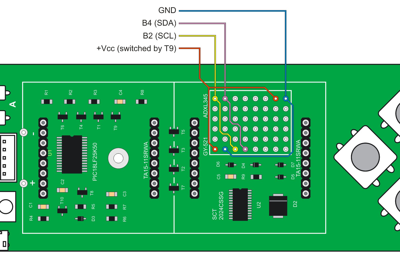
THE ACCELEROMETER MODULE IS NOT PROVIDED WITH THE BADGE. IF YOU WANT TO USE IT, PLEASE BRING ONE WITH YOU. SUGGESTED TYPE IS GY-521.
________________
HARDWARE:
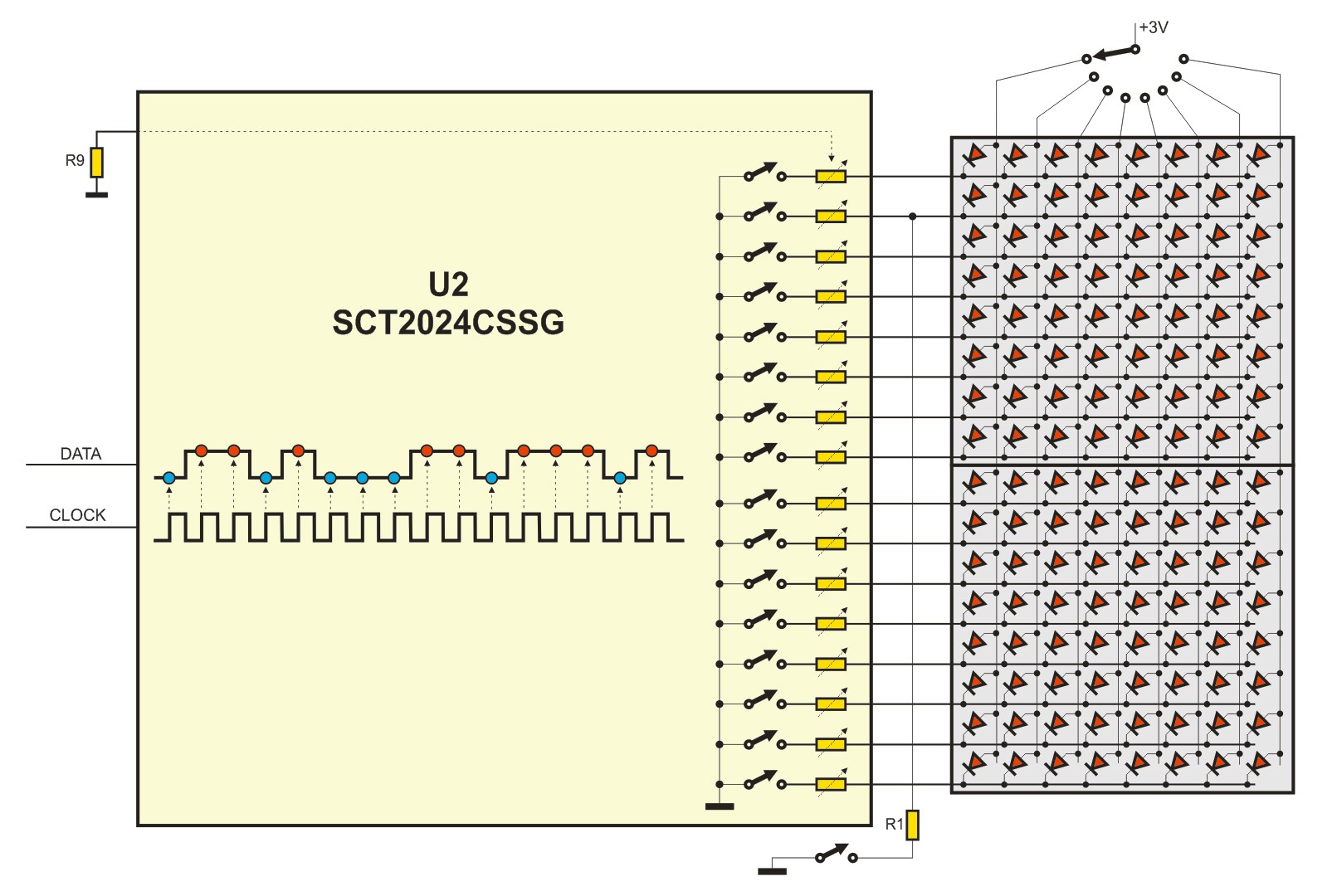
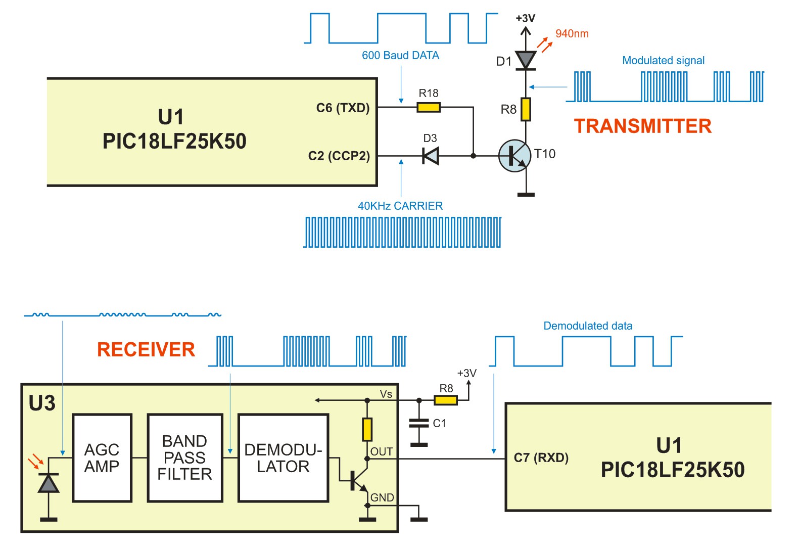
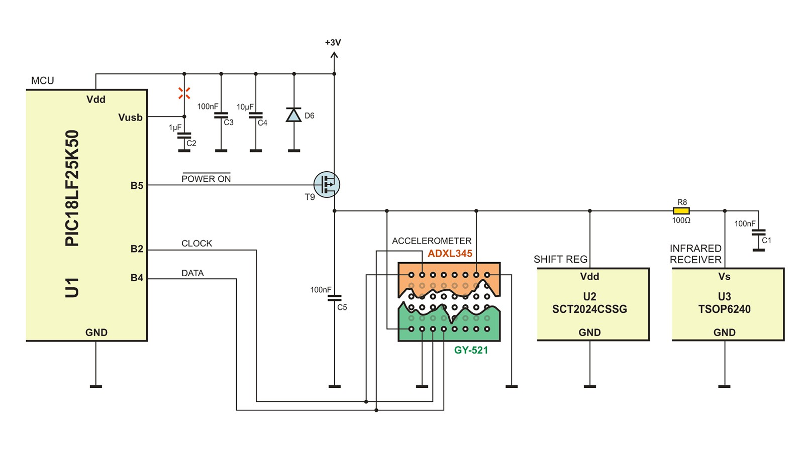
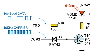
PCB dimensions are 48×176 mm. 8×16 LED matrix is built of two TA15-11SRWA blocks and refreshed by SCT2024CSSG constant current driver, permanently assisted by MCU. CPU clock is 48 MHz (which is 12 MIPS), so display refresh takes about 1% of processor time. Infrared transmitter is the single 940 nm LED, and the receiver is TSOP6240TTCD, which contains photodetector, AGC preamplifier, 40KHz band-pass filter and demodulator.
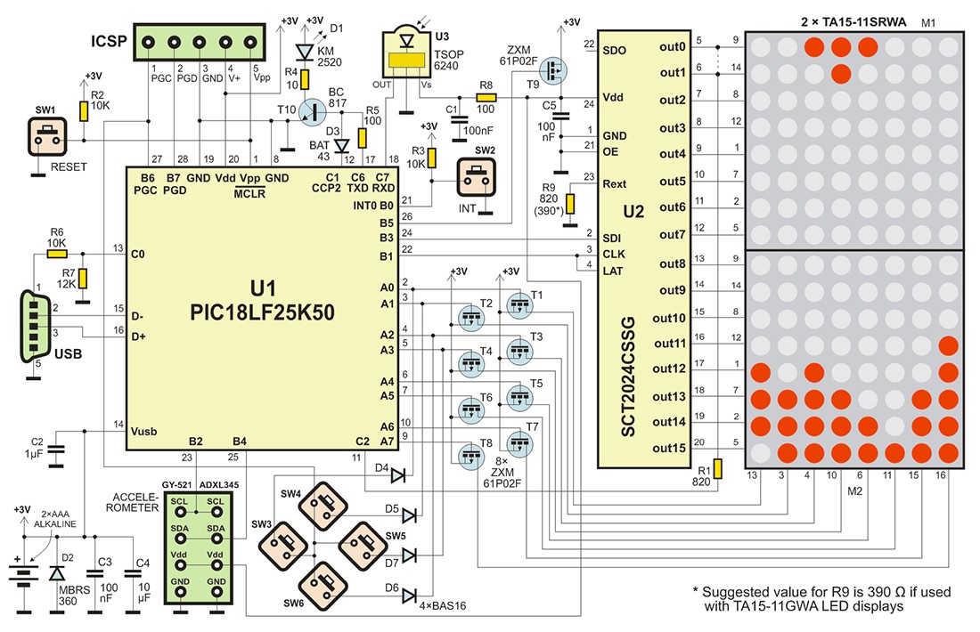
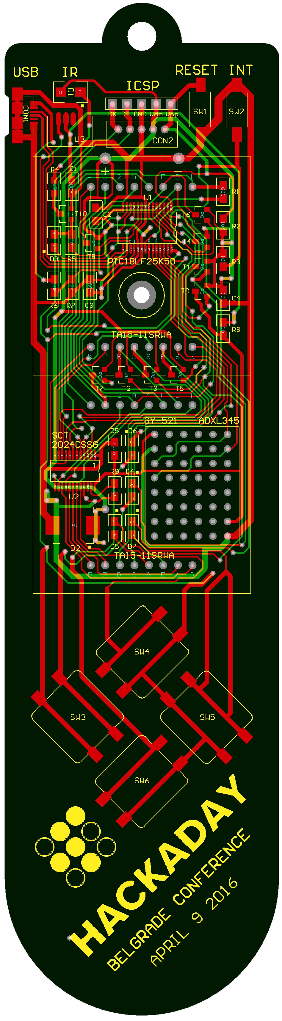
All parts are located on the front side of PCB, except batteries, which are on the bottom layer. Connectors, switches and infrared transmitter unit are visible, and all ICs and passive components are located behind LED blocks. Those blocks are in the sockets, so they are easily removable.
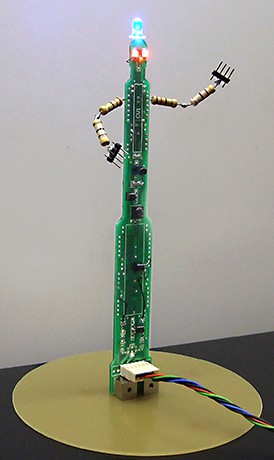
The first prototype (on the photo) had only 3 main tactile switches, plus one for ON-OFF-PAUSE control and one for RESET. The new version (which is still unavailable) is modified, and it has one more switch. The difference is visible if you compare photos with drawings and PCB screenshot. The switches are also larger (12×12 mm instead of 6×6).
BOOTLOADER
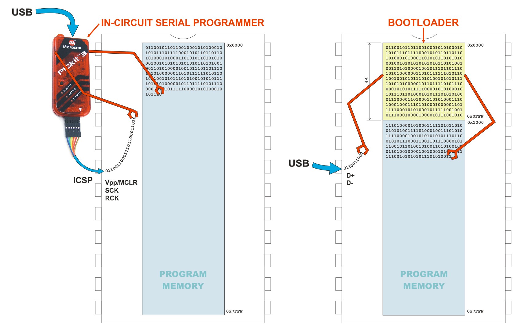
There is Microchip's MCHPFSUSB bootloader at MCU side, and USB HID Bootloader v2.90a for Windows at PC side. Here is the process of program memory flashing:
1. Write your program and compile (or assemble) it to make HEX file
2. Connect the badge to your PC using USB Mini-A cable
3. Open MCHPFSUSB Bootloader and load your HEX file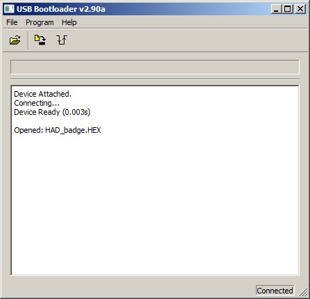
4. Click Program icon
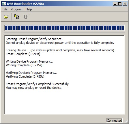
As simple as that. MCU accepts HEX file and self-programs itself. As the bootloader must stay intact in program memory range 0x0000-0x0FFF, your program should start at 0x1000. Bootloader will redirect all vectors (Reset, Lo priority interrupt and High priority interrupt) to new addresses, with 0x1000 offset. Bootloader will stay resident in MCU program memory, so it is ready for new program flashing.
KERNEL
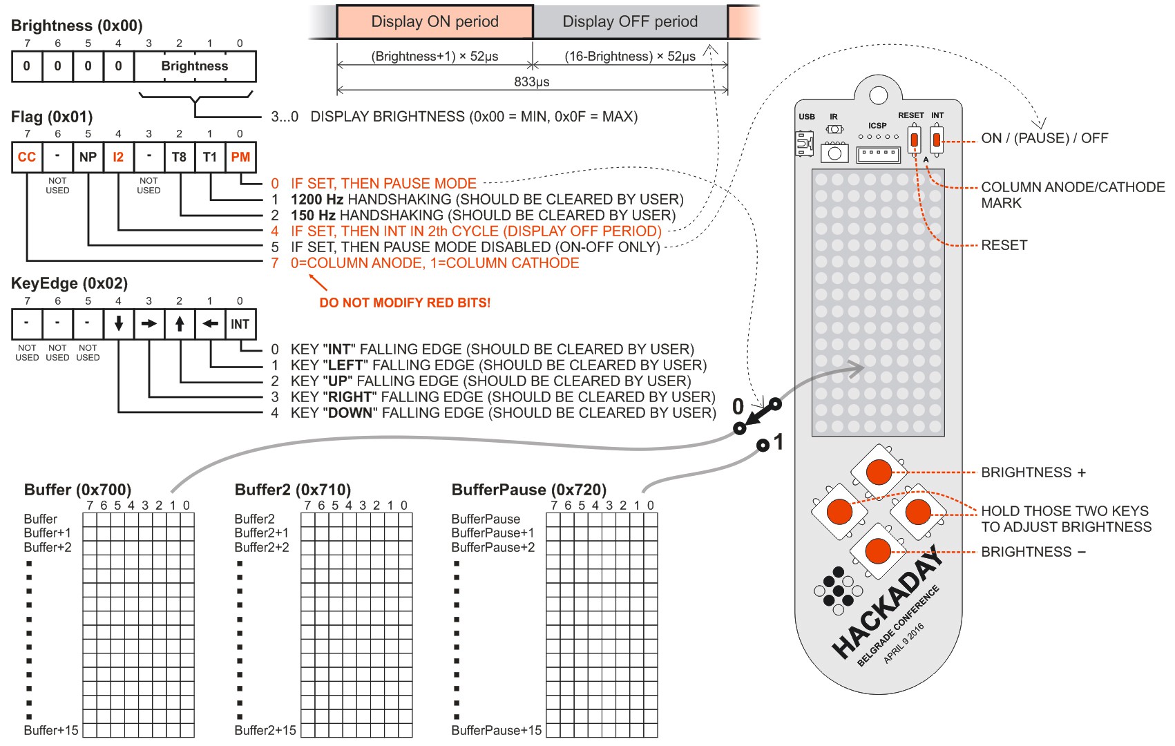
The short kernel supports LED matrix multiplex, and is completely located in Timer 2 Interrupt routine. This routine executes uniformly at 800Hz rate, so it enables 100Hz display refresh rate. Inside this routine, there is the key scanning subroutine with debouncer and edge detector, and full ON-OFF-Pause control, using the single key. So, MCU sleeps in Interrupt routine and user does not have to take care of that.
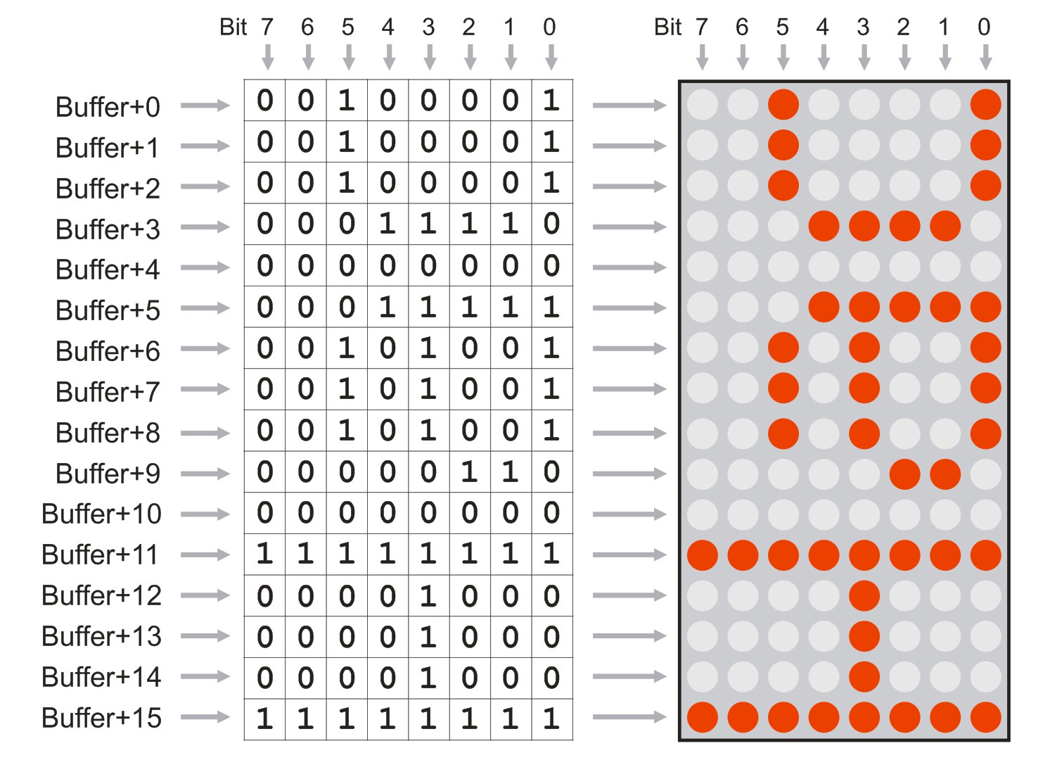
Frame buffer is in RAM, and everything that user writes in 0x700-0x70F will be imediatelly displayed on the LED screen. There is one more auxiliarry buffer, which is not displayed, but used for animated images. The third buffer (0x720-0x72F) is the special frame buffer, which will be displayed only in Pause mode. It may be useful for score displaying, pause symbol or any message.


a pity that badge doesn't use ESP8266 or Arduino...