Markus Dieterle
-
Back 4 good
07/12/2017 at 10:52 • 0 commentsHello everyone,
Sorry you all had to wait this long for an update. I'll try to get back to posting more regularly in the upcoming months.
So what's the current status of the TextEye?
New hardware options
Since I started the project last year, a few new hardware options have become available. The Raspberry Pi Zero has not only seen the additional camera connector, but is now available with additional bluetooth and WiFi capabilities - not really necessary for this project, but still a nice addition.
For the sound output, there are now some new soundboards which can be used with all Raspberry Pi boards, but have a form factor that's a nice match for the Pi Zero. The configuration is pretty much the same on all boards, but as for the additional funcionality (e.g. led soundmeters), so far these don't add anything that would make them a better choice for this project - so I'm currently sticking with the Adafruit I2S 3W Class D Amplifier Breakout that uses the MAX98357A chip.
For the speaker, I'm currently switching from the simple, wire-connected flat metal speaker to the mono enclosed speaker (3W, 4 Ohm) from Adafruit. It's a much better match for the amplifier board, and the enclosure should also add some necessary acoustical space for better volume and sound (which I would have had to add as part of the enclosure design with the other speaker). In order to connect this, I got some 90-degree JST connector which I'll try to fit on the amplifier board - so that the speaker can be easily connected (or disconnected for repairs or replacement).
I still need to to additional testing for the camera and lighting setup in order to decide which of the two Raspberry Pi camera modules - the normal or the "NoIR"-one - is better for this application. I also plan to test if the basic imaging results can be improved by using additional LED lighting or not (since normal, low power LEDs don't reach as far as a camera flash or a high power LED). For the tests, I want to compare the results without additional lighting with the results using the Bright Pi board from Pi-Supply as well as the results using the https://www.pi-supply.com/product/pi-light-camera-light-raspberry-pi-pi-pan/. Both options are sufficiently small and don't need too much power (allowing an overall longer use time for the TextEye before the battery needs to be recharged).
New software path
The different tests I did and the bad results from the (usually good and reliable) OCR software threw me back quite a bit. I did a lot of additional research - which showed that this specific kind of text recognition problem (using what the computer vision specialists call "natural images") has only been studied for roughly 4 years now.
The solutions which have been developed so far are basically variations of one single solution (as far as I have seen it for now). The documentation for this has a lot of theory and formulas, and hardly any code. And the related code you can easily find online has almost universally been written for Matlab, a closed source software for scientists and engineers that excels in mathematical calculations and numerical analysis. The code only works with online, direct control anyway, so even if the software was availbale for the Raspberry Pi platform, it would be difficult to use for this kind of headerless application.
As I wrote earlier (if I remember correctly), there was only one source that supplied an open source, Python-based code that could be used as a basis for a new solution.
Basically, after some image preprocessing some machine-learning-trained recognition algorithm is needed to first identify areas in the current image which likely contain text, and then these areas need to be analyzed further by either an additional, similary trained algorithm and/or OCR.
I've looked at different options for coding the machine learning parts in the last few months, and specifically which options can be used more or less directly on a Raspberry Pi (e.g. Google's nice Tensorflow library is currently tricky to install on a Pi, and it's not clear if the existing version can be used on the low-power Raspberry Pi Zero).
Since most currently available machine learning frameworks use Python (the specific syntax and "typelessness" seem to work especially well for implementing machine learning) I've started to learn the language and decided that I'll switch over the whole software for this project to Python for now.
This might not be the best option regarding performance, but I guess it should be acceptable as long as the training for the machine learning is good enough. Also, the training part can be done using the same code on a more powerful machine, and the training data can then be uploaded on the Raspberry Pi.
Once we have a solution that works well and sufficiently reliable, we can always work on making it faster, either by tweaking the algorithms, optimizing the processing at different steps or converting it into another programming language (likely a compiled one like C++).
Design conciderations
On the design and engineering side, I'm currently concentrating on the "core" solution which uses the Pi Zero, the Pi camera module, and some additional hardware components from Adafuit. It would be nice to have the power boost and the amplifier on a single add-on board with a direct header connection to the Pi GPIO pins - but that's an option for later. For now I'm planning to mount the two smaller boards into a 3D-printed frame, connecting them to the Pi with normal soldered wires (and maybe some header pins/plugs).
The pushbuttons for initiating the imaging and text recognition workflow as well as controlling loudness will likely sit on a separate PCB. I need to test if this can be placed back-to-back with the power/amplifier board combo, or if it works better as a separate placement (with addional standoffs etc.).
Further learning
Along with learing proper Python programming, I also have decided to take some additional time to learn more about image recognition and machine learning in general. I've tested out the samples for the "PyImageSearch Gurus" online course that's available on the PyImageSearch website. Even without knowing much, I found the examples to be well explained and (relatively) easy to follow.
My monthly budget (and current savings) don't allow me to invest in the single-payment option for this course right now, so I'll likely go for the more affordable monthly payment option, even if this means I cannot directly access all of the course content at once.
The new book from Adrian - Practical Python and OpenCV (with case studies) - also seems to be a good option. Maybe this is even enough for me to extract what I need for this project - I will take a closer look at it.
What's next?
I've already started with the new Python coding and currently work on hardware testing procedures within that. The Python learning process continues, and I plan to start learning the details about the image recognition and machine learning beginning later this month.
A new, updated wiring diagram needs to be drawn as well - I'll post that when I get around to it.
For the 3D modelling of the case, I'll have to find (or model) suitable 3D models for the parts I'm using. So far, I've made some simple hand drawings in order to record how I want the parts to be ordered in the final case (which I can scan in and post later). I now feel proficient enough in using Onshape for the 3D modelling, but I also want to try Fusion 360, as it offers a little more regarding additional freeform modelling (I currently don't need all the other bells and whistles it comes with - these really make the interface too bloated for my taste).
Regarding practical testing and optimizing, I am also thinking about getting an additional Raspberry Pi with the same add-on hardware that is needed for the TextEye and an additional touchscreen. With this, using the same base code, we could add a test program with a graphical interface and a "step-mode" that visualizes what happens in each step of the recognition process. Using this with a simple frame or case, we could use it to test and refine the software by actually using it in the environments and situations it's intended for. The optimized software can then be transferred into the "headerless" final design.
My goal is to get the core hard- and software working by the end of this year, even without custom cases etc. I'm not sure if the machine learning part will be completely finished by then, but it should be possible to at least get the framework far enough to be usable.
Ambitious to be sure... maybe I should quit my daytime job? :)
Until later...
-
A light change...
10/09/2016 at 17:37 • 0 commentsHigh time for another log update...
I'm currently on vacation, but I took most of the prototype parts and a computer with me as I hoped to get some additional work done (only to find out that the vacation schedule was a little too dense for that - well you need to get some relaxing done during holidays I guess :) ).
Breadboard prototype - current iteration
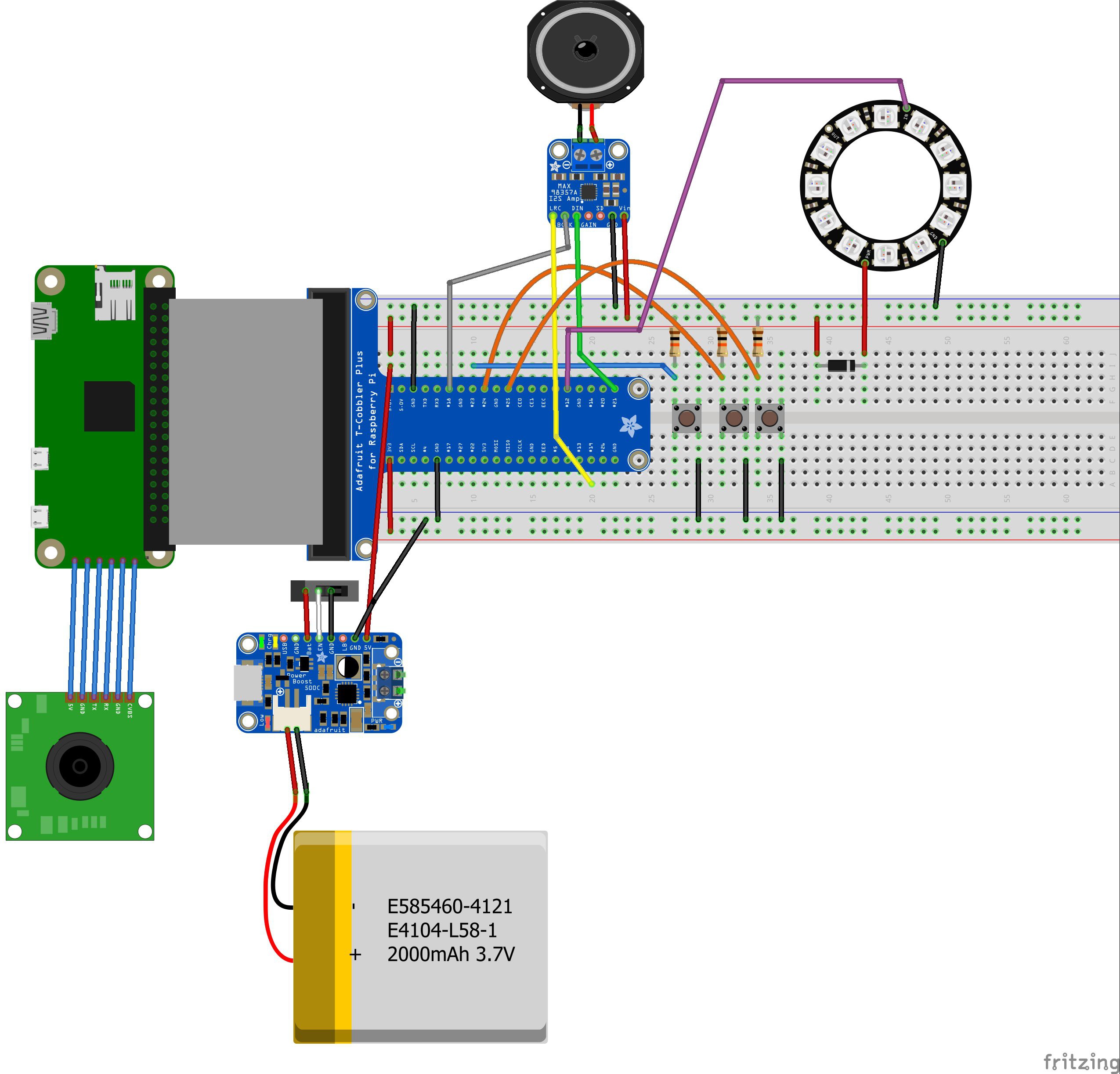
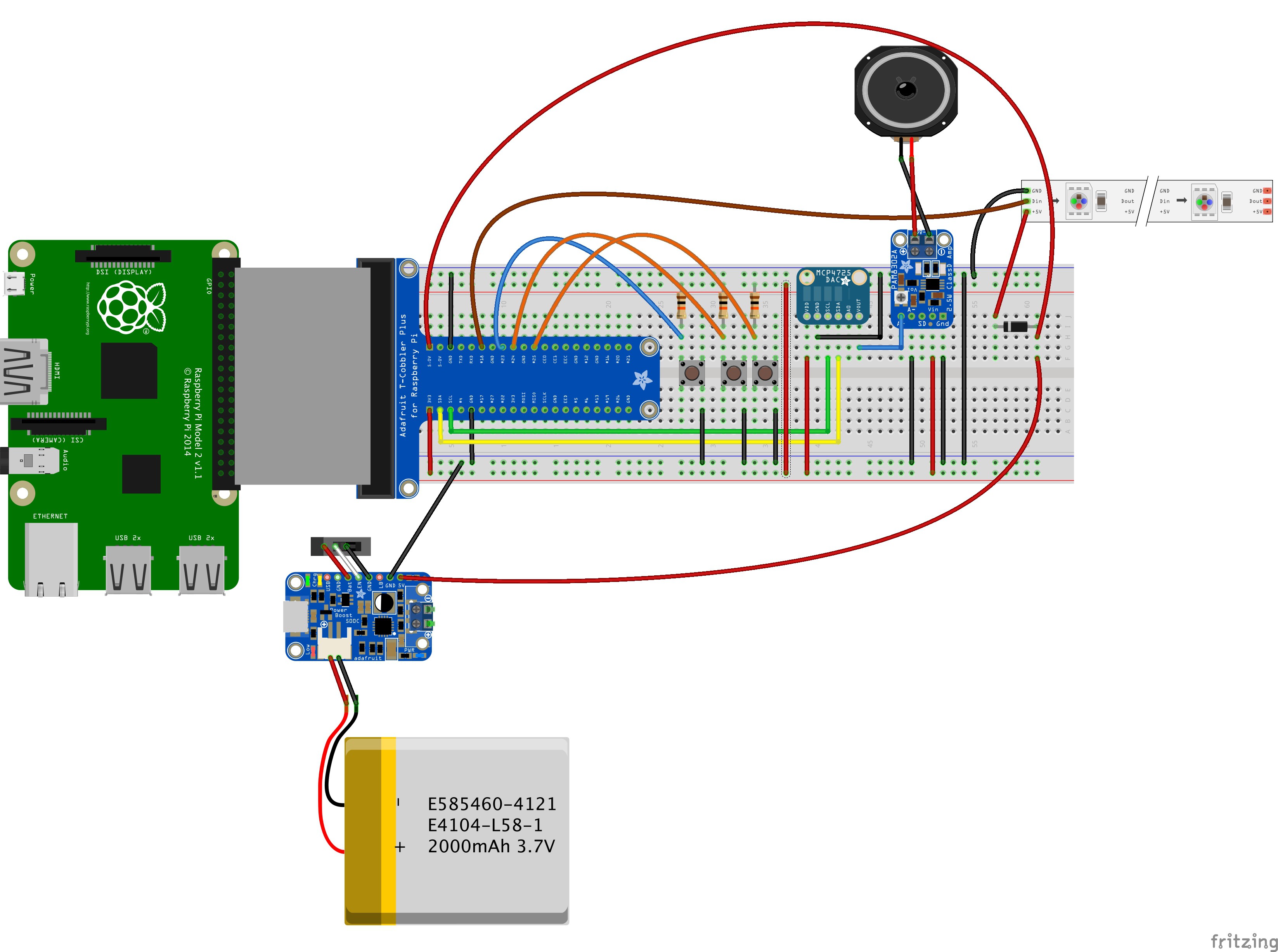
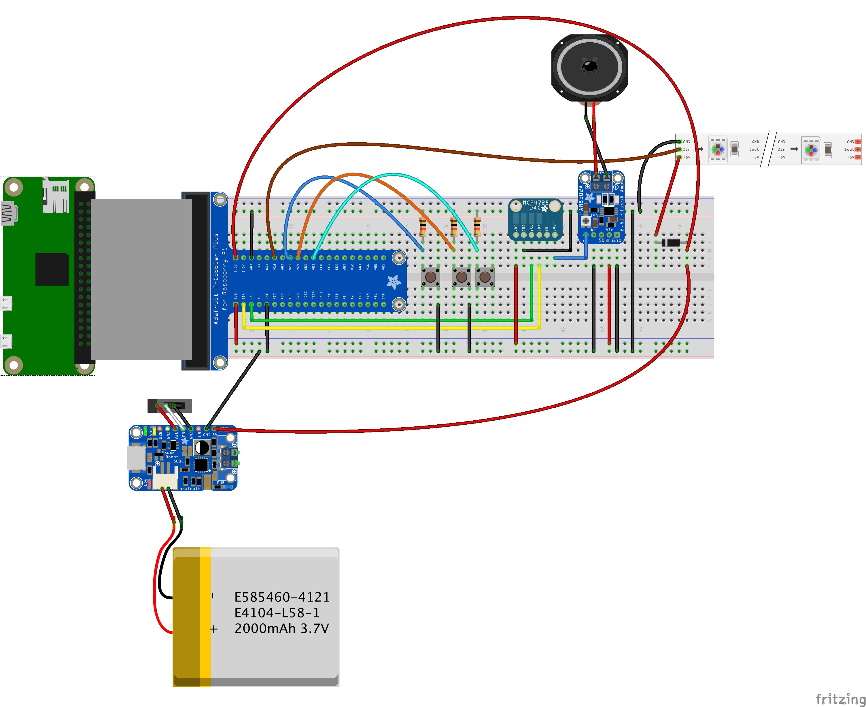
First of all, let's start with my latest Fritzing diagram for the breadboard wiring of the TextEye prototype:
![]()
Since I cannot currently find Fritzing parts for the newer version of the Raspberry Pi Zero or for any Raspberry Pi camera module, I took the older Pi Zero and a similar looking part and connected them with some direct line connections (although there is no actual connector on the Pi Zero right now), At least it is a somewhat realistic depiction of the actual prototype setup.
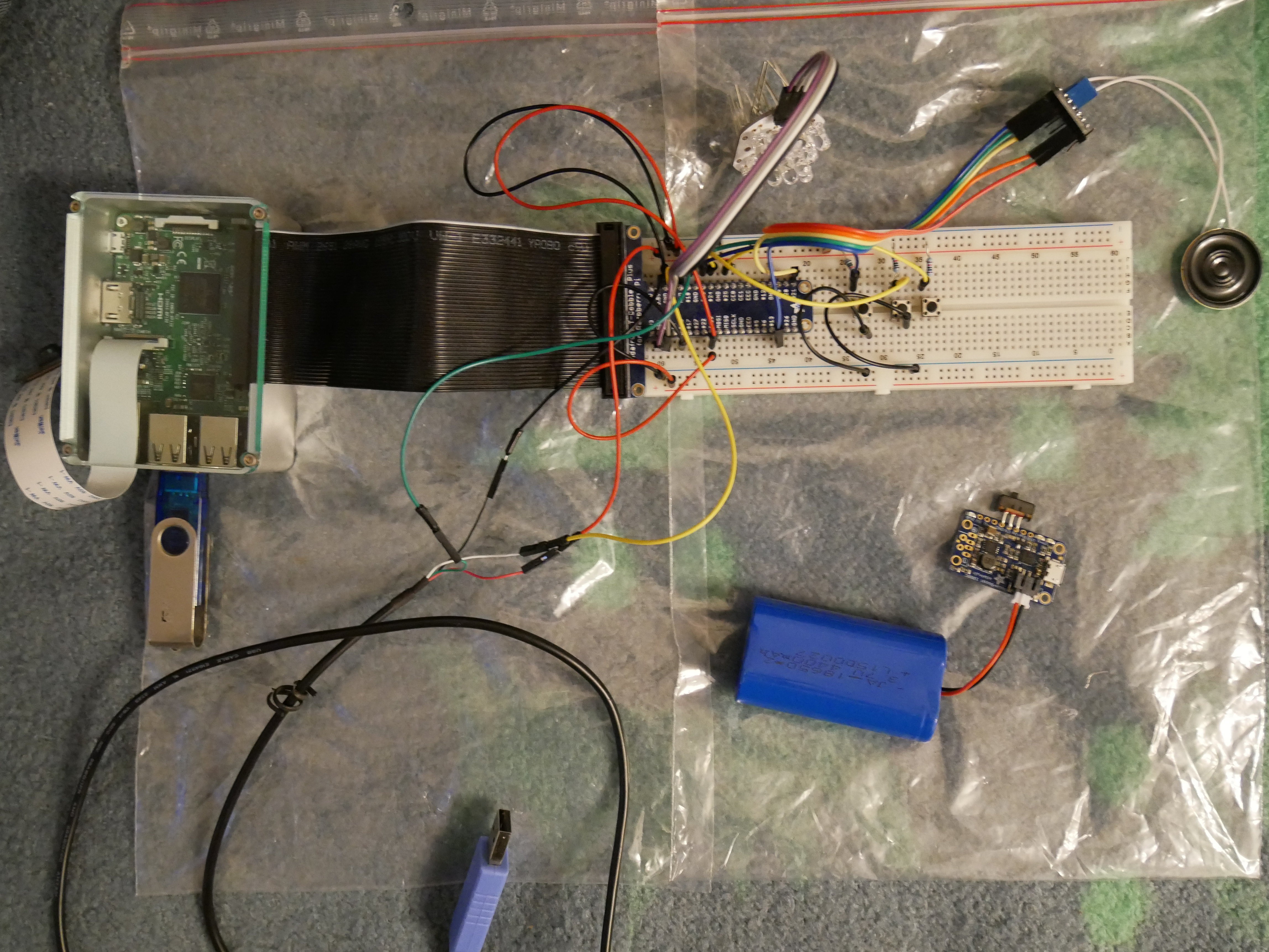
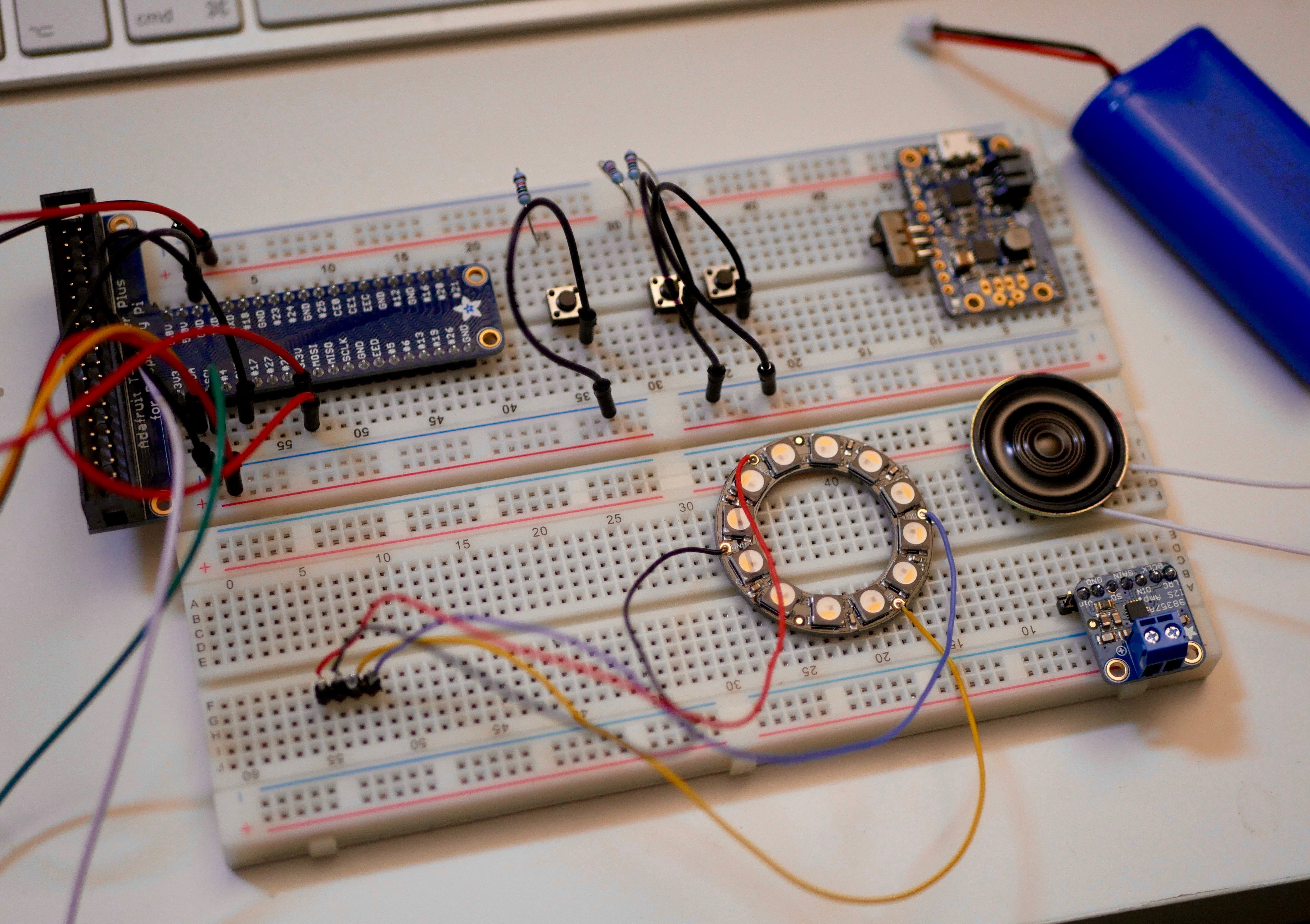
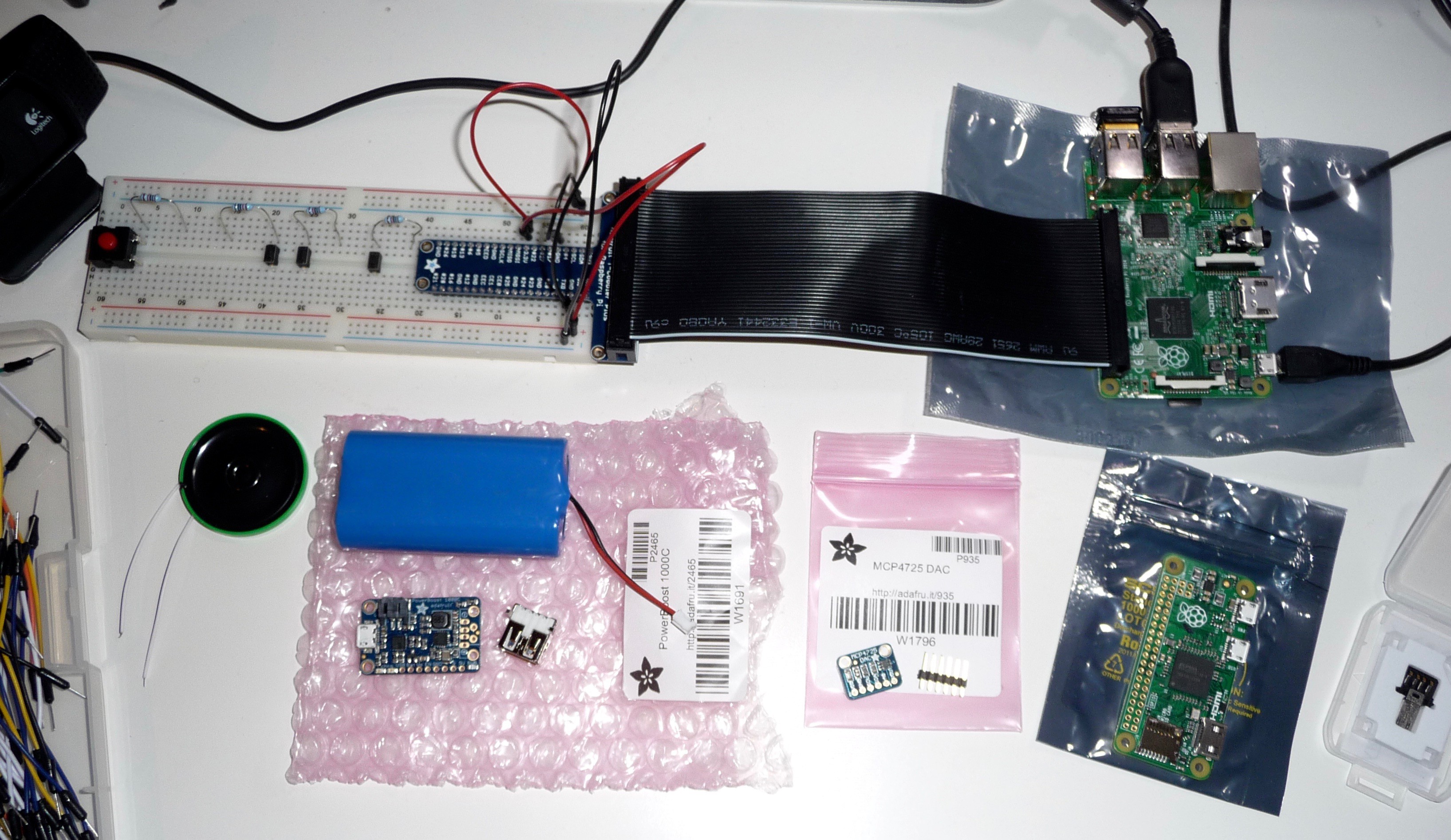
Now this looks pretty usable, but the physical prototype ended up being a little different:
![]()
If you compare the physical prototype and the Fritzing diagram, you'll notice the following differences:
- the physical prototype uses a Raspberry Pi Model 3 instead of the Pi Zero as the additional connectors simplify the development (updates, testing etc.)
- the PowerBoost 1000C is not yet connected to the prototype setup - mainly because I did not get around to the additional soldering before my vacation
- a TTL to USB serial cable (https://www.adafruit.com/products/954) was added for a direct serial connection to the Raspberry Pi
- since I did not bring enough breadboard jumper cables with me, one of the pushbuttons is currently not connected to ground (not a big problem right now)
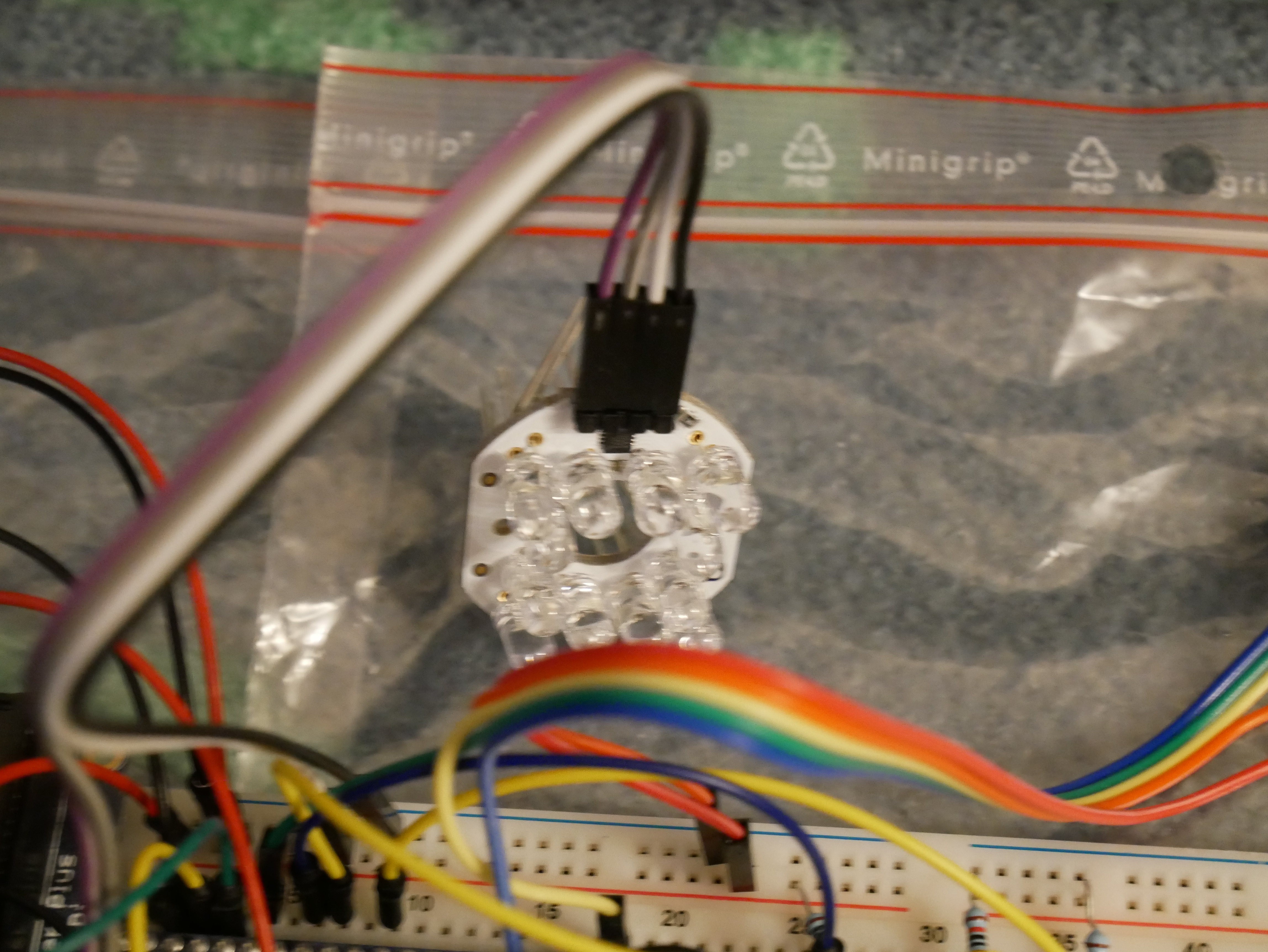
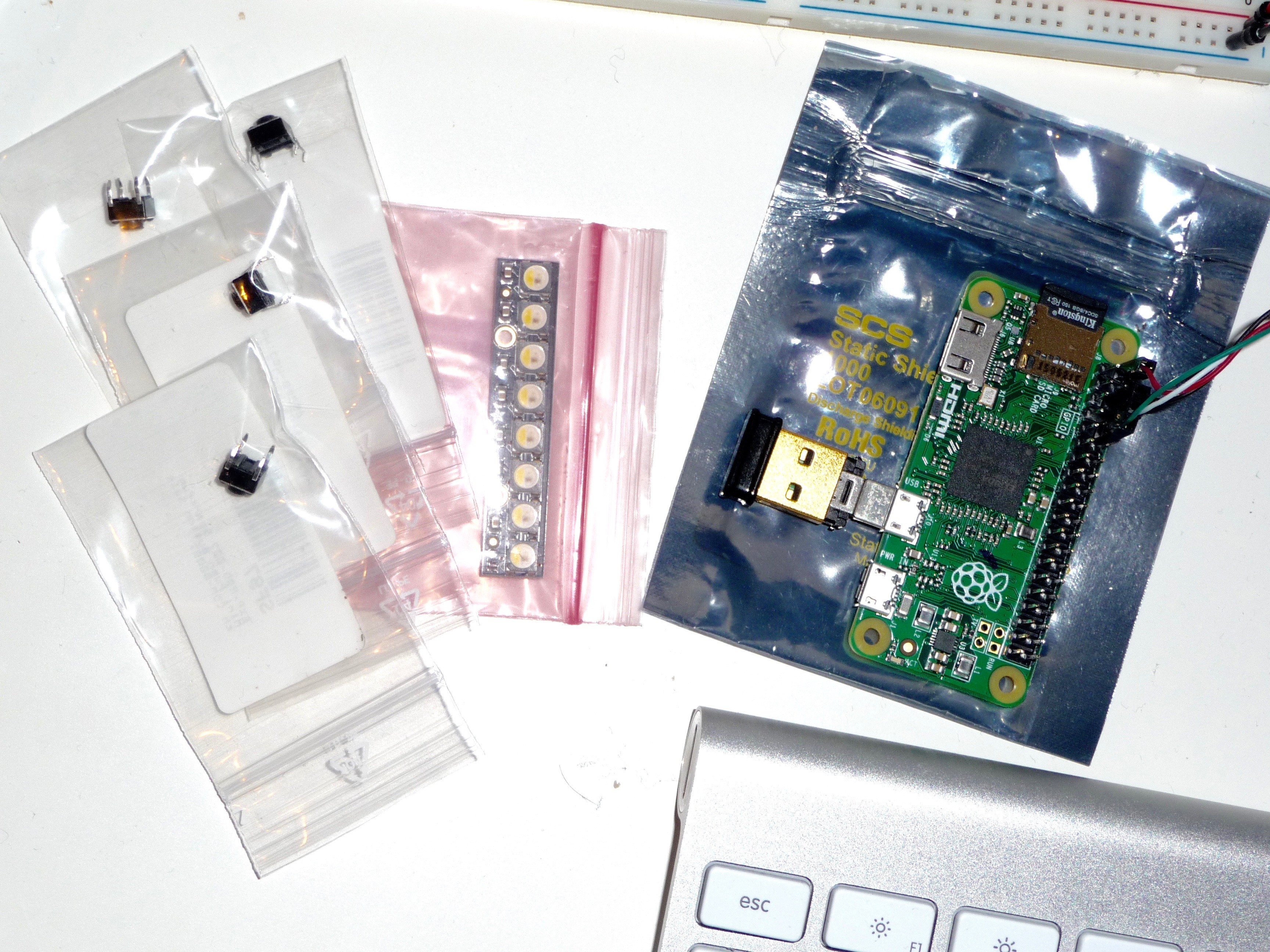
- last not least: the NeoPixel ring has disappeared and was replaced by the "Bright Pi" board:
![]()
The Bright Pi board uses simple white and IR leds instead of the RGBW leds of the NeoPixel ring or strip: https://www.pi-supply.com/product/bright-pi-bright-white-ir-camera-light-raspberry-pi/
Software (again)...
The main reason for using this "fallback" option for the lighting lies within the software development.
Since I'm using the C/C++ programming language for software development, I had already decided to use the "WiringPi" library for the GPIO access. When I looked at how to use the NeoPixel elements however, I found that the current option for this would be to use another library. Even though the other library would not access all GPIO pins, I could not be sure that the functions of both libraries would work alongside each other.
My programming experience related to hardware access tells me that a scenario like this, with functions from different libraries probably "fighting" over control of the same GPIO channels, is a potential recipe for disaster - unless you wrote both libaries yourself and know how to properly tweak them and make them work together.
From my research, I know that NeoPixel control mainly needs properly quick PWM access. With some additional time, it should be possible to use WiringPi to create a usable NeoPixel control library in C/C++. In order to get closer to a working prototype sooner, I chose to use the Bright Pi board instead.
The Bright Pi board is actually an I2C device with a simple 4-pin connection. Once I2C has been enabled on the Raspberry Pi through the advanced options in "raspi-config", you can pretty much follow the code examples on the Bright Pi web pages and combine them witn the WiringPi I2C examples in order to control the lights on the board from your C/C++ code.
While I have not finished the software yet (maybe I'm complicating things more then necessary...) I have got around to writing a quick and dirty test program today. I hope to get around to properly testing the hardware setup with this during the next few days.
Video todo
Due to my vacation (and a distracting bad cold) I'm still not as far along as I would like to be, but it's definitely no standstill.
For the Hackaday Prize, I still need to produce a short video showing of the project and a working prototype. Since the deadline for the main prize is October 17th, I had hoped to get around to doing a video sometime next week. But I've also entered the project into the "Assistive Technologies" competition, which has a deadline on October 10th. I've already received a mail telling me that the judging will start on October 10th, so I may not be ready to fullfill all requirements for the main prize in time.
That's a bit of a shame, but of course it does not mean that I will stop working on the project. The Hackaday Prize provides a nice additional motivation, but this project is important enough to be continued even without that. Apart from that, I already carried on with it after finishing the Raspberry Pi Zero contest, before someone nudged me to enter the project into the Hackaday Prize 2016 (hello Sophie ;) ).
With almost 400 projects that have been entered into the competition, several being already completed and fully working, I'm not too optimistic about finishing in one of the top spots anyway. There are a lot of equally good and interesting projects, and I don't envy the judges - some tough decisions have to be made...
For the moment, I'm just concentrating on getting the prototype to work with the complete workflow from taking a picture to the text-to-speech conversion of the OCR output. And that's all for now....
-
Changes and Upgrades
08/12/2016 at 15:02 • 0 commentsIt's high time for an update...
Since I did not add another log entry for quite some time now, this one is going to be somewhat longer. Let's start with the TL;DR version first:
- breadboard prototype is (almost) finished
- Raspbian and open source base software were reinstalled after some technical difficulties
- the TextEye software is undergoing a change from the initial C++ design to a more modular standard C design
- components for version 1 hardware prototype design were changed:
- Raspberry Pi camera module replaces USB webcam
- Raspberry Pi Zero was upgraded to version 1.3 (with integrated camera connector)
- NeoPixel ring replaces NeoPixel strip
- MAX98357A breakout board replaces the previous combination of DAC and amplifier breakout boards
- Raspberry Pi model 3 board was purchased for more direkt Pi development
- new digital camera for documentation and upcoming videos
- added 3D printing capability for custom case design
If you'd like to know more, keep on reading...
Breadboard prototype
The hardware changes described above have slightly affected the breadboard prototype, but not too much:
I'm plannig to update the Fritzing design after finishing the breadboard prototype, but that requires creating some new parts in Fritzing as I'd like to add the Pi camera module and connector cable along with the new Pi Zero v 1.3 board (for which there does not yet seem to be a ready made part in Fritzing).
Software reinstallation
In order to more easily transfer code and image files between the Raspberry Pi and my development system (and more easily create backups), I registered a USB stick and created a new mount point on the Pi. Mounting the stick, reading and writing to it worked fine so I decided to add the device to the device table and configure it for automatic mounting on startup.
The result of this was that the Raspberry Pi did not complete the boot process any more. No matter if had the USB stick plugged into the Pi or not, it just hang up during boot. I could not connect to the Pi any more, wether I tried the WiFi connection or the USB serial TTL cable connection.
So I went ahead and flashed the SD card with a new, updated Raspbian Jessie light image. After basic configuration, I reinstalled the software: GraphicsMagick, Tesseract OCR, Festival and WiringPi. As a final step, I copied my development folder with all the code, test images etc. back to the Pi SD card (thankfully I'd taken care to regularly save the code etc. before this misshap).
Another lesson learned... :)
TextEye software redesign
After finding some time for working on the code again, I had gained sufficient distance to it in order to see that it was getting to complicated and not modular enough.
With the experience from my tests and necessary future changes to different parts of the workflow in mind, I knew I needed a different code design that would allow easier swapping of the code within the individual workflow steps.
So I've started to do a rewrite using the standard C language, with different header and code files for camera functions, image processing, text recognition and speech output along with generic headers and the main file.
Hardware changes
Since I started this project, new hardware has become available that allows the TextEye to be smaller and a little more efficient.
With the original Raspberry Pi Zero, I could not use the Pi camera modules as it did not have a camera connector port. The recently updated version 1.3 does have that, so I can switch from a USB webcam to the current 8 megapixel versions of the Pi camera or the NoIR camera module. That makes it more compact, more easy to power from the Pi and also upgrades the image resolution.
The NeoPixel ring with 12 LEDs should work just as well as the NeoPixel sticks which I chose first with regard to brighten up the imaging area. It fits better into the overall design and also should slightly improve light distribution. I still have to test this option though. I've also gotten hold of the "Bright Pi" kit from Pi Supply as a possible alternative. This is a little more bulky, but adds some IR LEDs into the mix, which should be a better option if I decide to use the NoIR camera module instead of the normal camera module (the images have to be processed anyway, and the NoIR module should gather a litte more light under any circumstances).
On the sound output side, the MAX98357A breakout board replaces the previous combination of DAC and amplifier breakout boards. This solution is more compact, helping to reduce the size of the final hardware.
I'm planning to wire the final components together over the weekend. For now, here is a quick look at the soldered parts:
![]()
Raspberry Pi model 3 development hardware
While the transfer between the Raspberry Pi and my main computer works fine with FTP as well as a network mount option, I have to switch back and forth between coding and testing. So I've decided to not only copy the code to a USB stick, but also get a Raspberry Pi model 3 as an improved development platform.
For this, I flashed a new SD card with the standard Raspbian Jessie OS and installed the same software on it. I also started to install OpenCV, but the process here isn't done with just a simple "apt-get install" command.
I will start using this platform regularly in the future, as it not only allows me to test my code faster (as I can directly code on the target platform), but also gives me the option of testing some desktop-based stuff that will likely come in handy for improving the text recognition and the image processing.
New digital camera
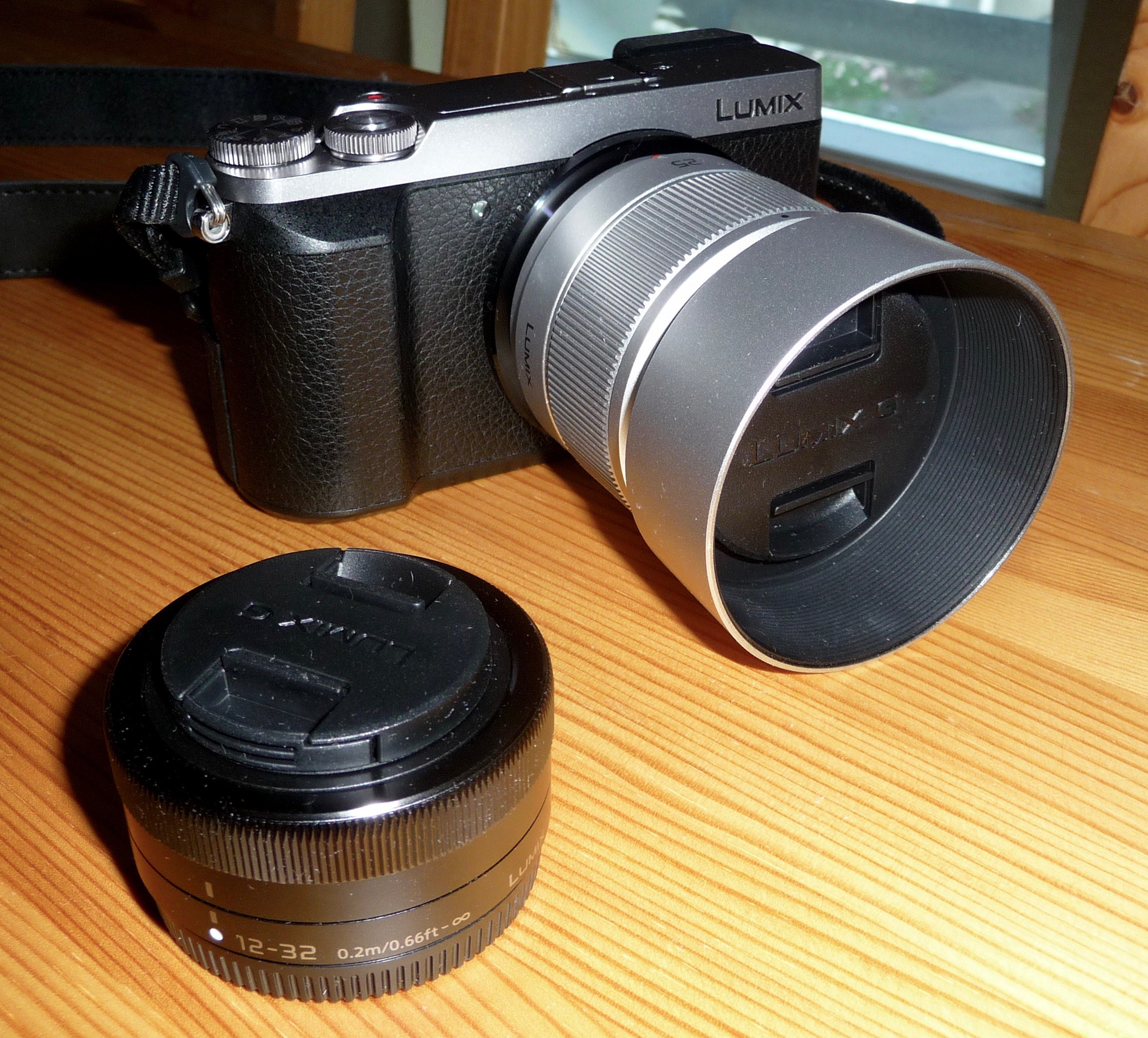
The project pictures I've taken so far (apart from the ones taken with the two webcams) were produced by my trusty Panasonic DMC TZ-5. While it's still a nice and enjoyable camera, I've been longing for an upgrade for some time now. I want to explore photography more deeply in the future, and since the camera does not offer many manual control options and has a fixed zoom lens, I wanted to switch to a mirrorless camera that's not too big but much more capable.
So I recently got myself a Panasonic DMC GX80 (also known as GX85 or GX7 Mark II in other markets around the globe) with the 12 to 32 mm kit lens and an additional 25mm F1.7 lens. Along with a better image quality and better low light performance this also gives me the option of recording decent videos in 4K or 1080p resolution (altough I need to record the sound externally and synchronize it with the video in post-processing):
![]()
I'll use that for documenting the further progress of this project and for recording the project video which is a requirement for the Hackaday Prize 2016. I also plan to do some additional videos about the project. It might take a while though since I'm a complete beginner as far as video production is concerned. Another learning frontier... :)
3D Printing capabilitiy
Since the project started, I've planned to design a custom case for the final hardware that should be 3D printed. As the parts list for the version 1 prototype is now complete, I can go ahead to create a design, at least after the hardware and sofware start to work properly (which is much more important anyway).
From my current location, the nearest maker spaces are quite a bit away and take a lot of time to get to. I could send off a finished design to another maker or an online 3D printing service, but when details need to be changed, the design prototyping process is not that fast, requiring a lot of time and money.
Thanks to the seed money for this project, I was able to use the money I initially saved for the camera upgrade (which I would have done anyway this summer) for buying my own 3D printer. This is another thing that I wanted to to but normally would have had to wait until next year given my normal monthly budget.
I already did a lot of reading and research on 3D printing, and I also thought about how I would use a 3D printer, so I was able to come up with a list of "must have" and "nice to have" features.
I finally decided to go for the Craftbot Plus from CraftUnique - not the cheapest option, but a really good "bang for the buck" option. The Craftbot 2, which has just been launched, is a little more expensive, but the mechanics and extruder are the same. It mainly adds wireless connectivity via WiFi and the internal electrical wiring is said to be improved. The older Craftbot+ is still available though (in the same palette of colors) and remains a good option.
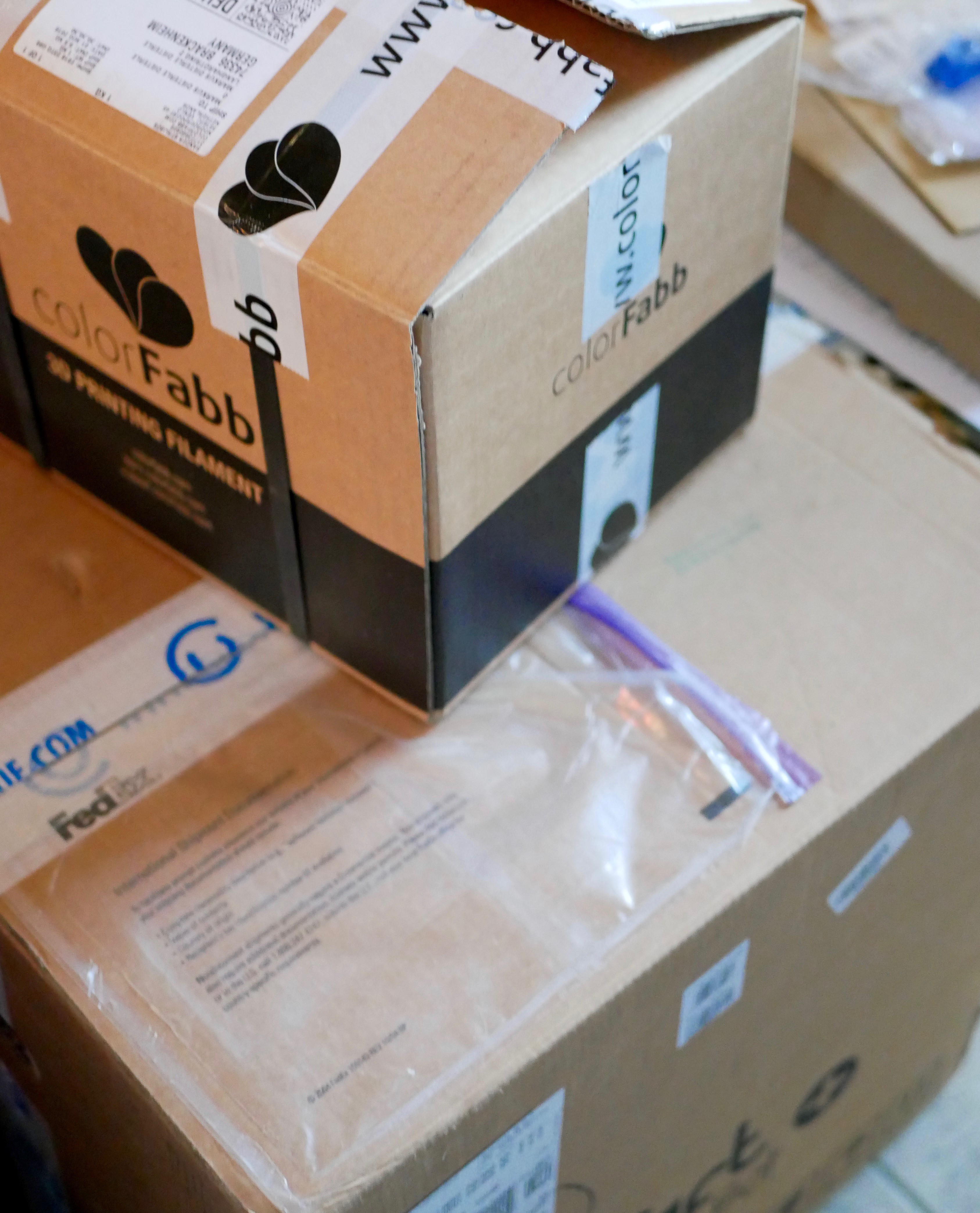
I just received the printer and hope to get around to doing some test prints in the next few days. At the moment it is still in its box:
![]()
![]()
As you can see, I also went for some additional filament from ColorFabb (some PLA and nGen).
Next steps
There are still several steps I need to take in order to get this project properly "off the ground":
- finalize the prototype hardware and transfer it from its breadboard form into a full prototype
- finish the basic TextEye software and get the workflow running, upload the code to GitHub
- design and print a case for the prototype
- create a custom project logo
- update the parts list and build instructions
- add more documentation
- create a project video (and additional detail videos if I can)
- enter the project into the "Assistive Technologies" sub-challenge of the Hackaday Prize 2016
- try to improve the image recognition and OCR part of the software
- work on the "add-on" version 2 prototype (that attaches to a digital photo camera)
Sounds like I need to take a vacation from my daytime job in order to do this... :)
I definitely have to prioritize some steps over others here. For this year's contest, I guess I'll focus on the version 1 prototype, getting that up and running up to the point where I can focus on improving the software.
I will try to keep the version 2 prototype in mind when finishing the software. Basically this second version will need to regularly check for new image files in a different storage location, unless I can easily tap into the button press signal from the digital camera. The hardware connection between the external camera and the Raspberry Pi still has to be worked out, but I already have some ideas for this. The rest of the hard- and software is basically identical to version 1, apart from a different case that needs to be fitted to the camera (I'd like to keep the camera unchanged, but of course you could crack it open and maybe transfer the camera internals into a new, expanded, custom case if you want).
As far as the videos go, this will be another learning experience for me, so it might be a little rough at first.
Stay tuned...
-
Busy days, hardware frenzy and imaging insights
06/03/2016 at 14:47 • 0 commentsHello and thanks a lot to everyone who's signed up to follow and like the TextEye project so far! You really keep me going even in the face of severe problems.
I currently mostly work on improving the overall solution and finalizing the first proper version, but sadly don't have much to show so far. That should change over the next few weeks while I work on implementing a better time management so I can get more things done in the little time I currently have.
So what's happening?
Decisions on first version hardware
Since I started the project, a lot of new hardware components have become available. Some of those are quite helpful for creating a really small and easy to carry mobile text reader solution, even more so than what I originally imagined.
For example, the USB webcams work pretty well with the different versions of the Raspberry Pi, but you need to take them apart and also solder a shorter USB cable to them in order to get the size down. Thanks to the recent updates to the Pi camera modues and the Pi Zero - where the new version now comes with a camera connector - we can now use the new Pi Zero with a Pi camera module (normal or NoIR) and get a higher resolution than what most USB webcams can offer, all in a small, easy to fit package.
While both camera options don't have the kind of shake reduction that you can get in modern digital photo cameras, it's a very convinient option.
In combination with the Pi camera module, I'll try to add a small NeoPixel ring with RGBW LEDs instead of the NeoPixel stick I use for prototyping. This can fit around the camera lens, and it adds better white light for more brightness when taking pictures. It might not be necessary for the NoIR camera module, but I have not yet testet that (given that the OCR generally works better with greyscale images, the NoIR module might be a better choice as long as it produces enough contrast in the images).
On the audio side, Adafruit recently came out with a new and nicely small mono amplifier breakout board (the MAX98357 I2S Class-D Mono Amp) that can be connected to a Raspberry Pi using I2S. While I was able to get the Pimoroni pHat DAC board which adds audio output capabilities to the Raspberry Pi Zero (and improved audio output for other Pi models), it took quite a long wait (about 2 1/2 to 3 months) because it was out of stock and took a while for new boards to be produced. From what I've seen from Adafruit - through a lot of their videos, including the "factory tours" Ladyada did on a few occasions - I'm confident that the new amplifier boards won't be unavailable for that long. And I like the smaller form factor - so I've decided to use the new board with the Pi Zero as part of the first version of the TextEye.
So while I'm still prototyping with the Pi model 2, the first "usable" version should use the new Pi Zero, with camera module, NeoPixel ring, Adafruit MAX98357 I2S Class-D Mono Amp, mini metal speaker and USB-rechargeable battery. I've already ordered the new hardware modules and should get them soon.
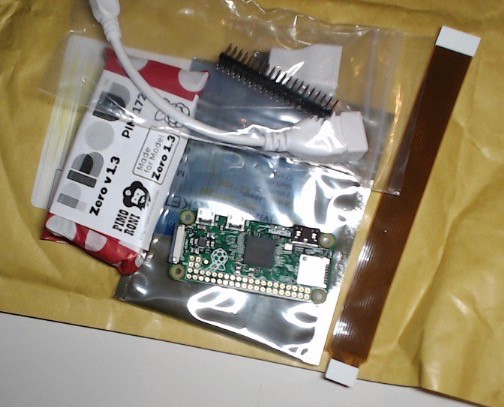
I thought that the Pi Zero might be a problem, as it has been hard to get in the last few months. But it actually arrived just today, after I ordered it directly from Pimoroni in the UK only a week ago (where the online store already stated that because of Pi Zero related shenanigans orders could only be handled with a 3 to 5 business day delay - and you can currently get only one Pi Zero per customer).
![]()
As you can see, I went for the basic kit which included headers, USB adapters and a small case. I also added the camera cable which is needed in order to connect the Pi camera module (which I already have) to the new Pi Zero (the camera connection is a little smaller than on the other models).
Imaging research and insights
If you read through my earlier project logs, you know that while the different hardware and software components each work pretty well, using them for a mobile project like this takes them beyond the limits of what they were originally created for.
The important central component of this project is the OCR software. The tesseract software, like all currently available open source and commercial closed source OCR software, has been optimized for being used with images of text created by flatbed or document scanners. It works really well for that, even when the scanned pages or documents also contain images along with the text.
With a mobile, handheld camera though the image quality is totally different, and the standard OCR algorithms can't cope with the blur, distortion etc. which is normal for this kind of image. Even when I used a digital photo camera with shake reduction, automatic white balance etc. the text images did not work well for extracting any text with the OCR program.
It was clear that the project needs a better solution in order to come close to the original idea of a mobile text reader - otherwise I can only convert this to a non-mobile solution which only replaces a more expensive PC reader setup.
One idea I had was to move the actual image analysis and text recognition over to a cloud service on the internet. Such things have already been done on smartphones, where you can use the mobile internet conneciton and the integrated camera with a connected app which translates text on signs in foreign languages, e.g. in the Google Translate app. Google's cloud vision service, which can be used though the cloud vision API, might be able to provide the needed functionality.
The downside is twofold though: you need to have a mobile internet connection (preferably with a relatively high bandwidth and speed), and from what I've seen so far there is no free online image analysis service right now, so you have to pay some money in order to use that. In addition to that, depending on where you are, you might not have mobile internet access at all, wether it's WiFi or GSM/UMTS/LTE based.
Thankfully text recognition from "natural" images - in this case meaning photos taken with digital cameras, smartphones etc. in everyday, real-world conditions (as opposed to the images from flatbed and text scanners where parameters like basic alignment, lighting, contrast etc. are much more controlled like in a laboratory) - has become a topic of interest for more and more scientists in the field of computer vision and imaging. There are no standard, easily usable solutions so far that we can just download from GitHub or elsewhere, but the topic is being investigated by several specialists and at least one usable method has already been found.
The main idea here is to combine advanced pattern recognition, image analysis, and image enhancement techniques and turn the information inside the image into a searchable hierarchical structure, where characters can be properly located and translated into letters. While the final step is the same as with "normal" OCR, the image analysis process before it is more complicated.
As it is now, the pattern recognition has to be trained with different images in order to improve the reliability of the text recognition, similar to the audio training for your voice that you need for a really good voice recognition that works well for dictation. There are some basic but usable training data sets already, and there is some information about how to expand that with images of your own. This is an interesting application for the area of machine learning.
Francesco Pochetti, a highly skilled guy from Italy with interest in machine learning and similar topics, has written a really good article on the topic back in 2014, and even created some code to go along with it that can be downloaded from GitHub. The code is written in Python, which I've yet to learn, but is easy enough to read, especially with the explanations from the article.
Since other stuff I've seen in this area uses Matlab or similar mathematical analysis software (which usually needs a graphical interface and adds another software layer when you run the code for the image analysis - and needs quite a bit of computing power), Francesco's approach seems more usable for this project, and also allows for later optimizations as well as a C/C++ conversion (for a possible speed improvement).
Before I implement this however, I'm keeping the current software combination for development and testing. My current approach should allow me to switch out the OCR software relatively easy later on since I'm not integrating everything into a monolithic program.
That being said, it also remains to be seen how well the currently available Raspberry Pi models - especially the Pi Zero - can actually handle this kind of advanced image analysis. It's pretty heavy on the computing side, with lots of mathematical calculations and a good amount of data being involved.
Stay tuned... :)
-
Breadboard noob :( (and DAC board update)
05/17/2016 at 18:14 • 0 commentsI'm slowly coming back to spending more time on this project. Progress could be faster - I still have to work on my time management skills, and maybe stop doing additional research at this point as it's taking too much time right now.
Breadboard wiring errors
Just as I was preparing the components for the hardware prototype wiring, I noticed some errors in my Fritzing designs - thankfully I noticed those before connecting and powering up everything. Apart from one missing GND connection line on one of the buttons and another missing crossover line for the 3.3V power line, I accidentally mixed up some power and ground connections - which could have been disastrous if I hadn't caught that before the fact.
I have to admit that this is the first time I'm working with a standard plugin breadboard as well as the first time I'm working with the Fritzing software. Good thing the physical breadboard has some nice plus and minus signs for the default usage of the main lines along the long edges of the board...
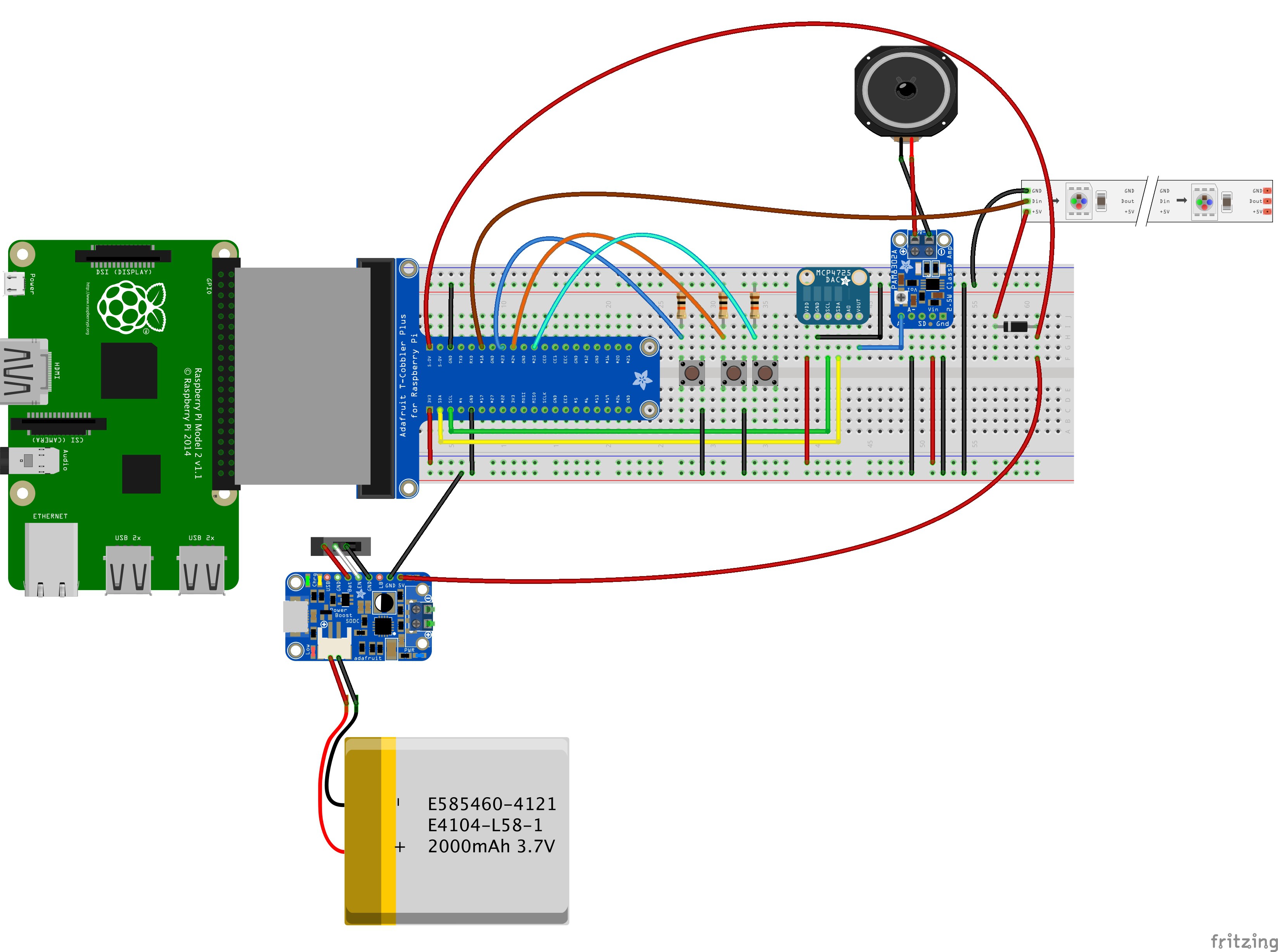
I fired up Fritzing again and corrected the errors. Here is the new version of the prototype layout using the Raspberry Pi model B+/2/3:
![]()
And here is the same corrected sketch with the Raspberry Pi model Zero:
![]()
In order to recreate this setup using real hardware, I need to do some basic soldering on a few components. Otherwise I won't be able to connect them to the board. Then again, once the setup is working, I'll have to do more soldering for the final prototype anyway.
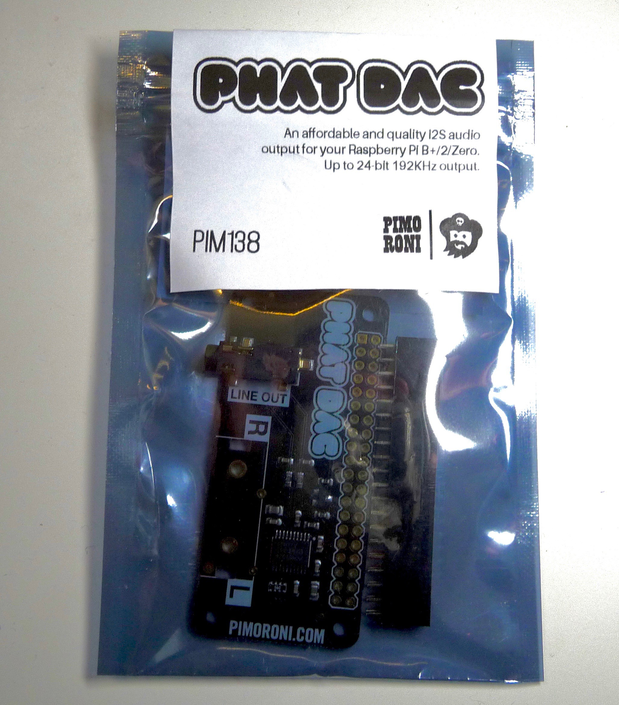
DAC option: PiMoroni pHat DAC board
The incredible has happened a few days ago: I've finally received the PiMoroni pHat DAC board which I ordered quite a while ago (a litte more than 2 months if I remember correctly - I could look up the exact date):
![]()
While I've already incorporated the Adafruit MCP4725D DAC breakout board into the current hardware design as an alternative DAC and audio output for the Raspberry Pi Zero, the pHat DAC board has the same form factor as the Pi Zero, and could possibly be a little easier to set up and use.
The downside - as far as I can see it so far - is that the wiring connections to the other parts like the switches, resistors etc. can be a little tricky to do with the board connected to the Pi Zero trough the standard headers. I may have to add the additional wiring either to the back side of the Pi Zero or to the pHat DAC board on top, or come up with a kind of t-junction solution for the necessary pins. Or maybe using some "flatband" cable just for the few really necessary connections between the Pi and the DAC board, and single cable connections for the switches etc. is the better option - if anyone has worked on similar wiring options in the past, and can share some advice and experiences, please add them in the comments...
-
Fast Delivery
04/30/2016 at 12:24 • 0 commentsJust a short update:
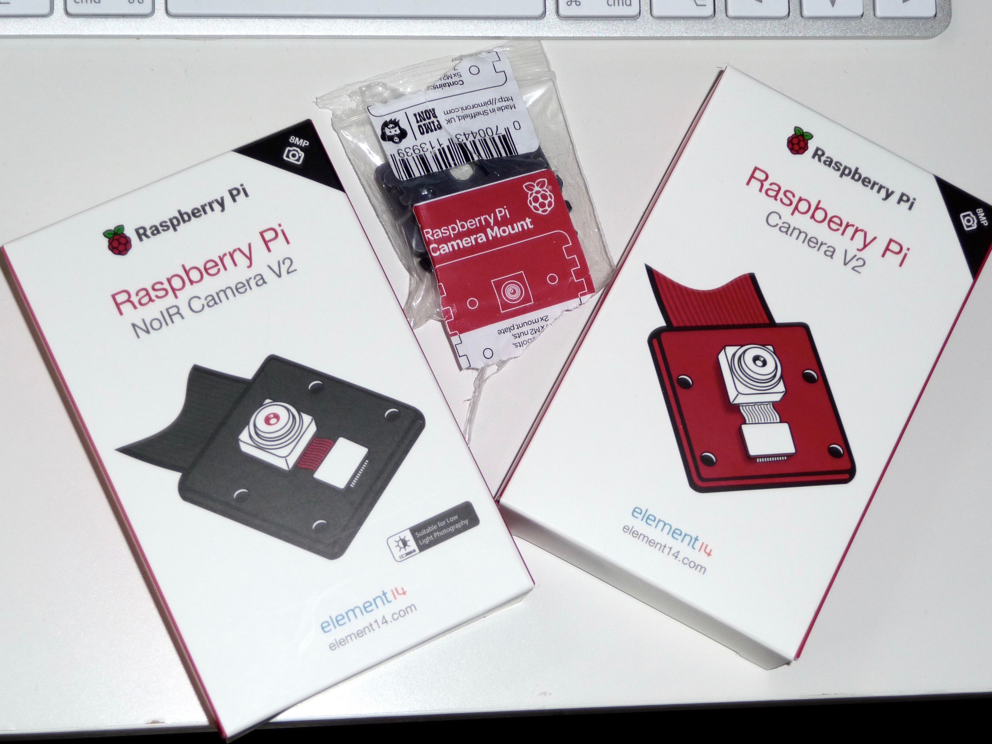
I only placed my order for the new Raspberry Pi Cameras on Thursday, and just today my neighbour gave me a small packet that was delivered sometime on Friday when I was absent - with just that delivery inside!
So thanks to the great work from the people at EXP-Tech I've already got the latest Pi camera modules in my hands, along with two little PiMoroni camera mounts:
![]()
Great stuff!
I've bought quite a lot of stuff from EXP-Tech during the last few months, especially Adafruit components as they are one of the local distribution partners here in Germany. And while they don't offer all of the Adafruit parts, they are doing a great job nevertheless. Just a few weeks ago, they were really fast to send me a replacement board when I discovered that I had received the wrong one - I just wrote in and they promptly send me the right board the next day, before I managed to send back the wrong one to them.
So if you are in Germany and need some electronics parts, especially Arduino-connected stuff and Raspberry Pi stuff, you should definitely check them out!
I'll hook the cameras up to the Pi Model 2 and/or Model A+ in the upcoming days and take a buch of pictures with that. I'm really curious about the image quality...
-
Alive (and kicking... :) )
04/29/2016 at 12:54 • 0 commentsIn the last few weeks my daytime job has kept me pretty buzy, mostly with a huge multi-month project that has just entered the "hot" phase.
While this stops me from being able to work on the TextEye project as often as I'd like to, and will continue to do so at least until August this year, I haven't abandoned the TextEye project and will continue to work on it.
Thanks to everyone who's been following this project so far - I hope you'll bear with me and keep coming back.
For today's log I'll just do a short status update. Luckily, I had already planned a one week vacation period for the next week since January this year, so I should be able to give this project a much needed boost.
So what's the status?
Software status
On the software side, I've created the basic structure for my "workflow" application and started to write a special C++ class for that which is designed to be flexible enough to easily switch out external and internal application components for creating, processing and OCR'ing the images etc. It's not finished though, and I'm currently thinking about creating a smaller, much simpler prototype app in order to speed things up a little.
I also found an interesting, open source image processing app which is aimed at optimizing pictures for "digitizing" books and magazines. The software is called ScanTailor, and while it's not the newest piece of software, the last GitHub updates did not happen that long ago and it seems usable enough.
On the downside though, it's essentially a desktop application which needs the visual checks to either acknowledge the automatically proposed optimiziations or do manual optimizations. With that, it can really optimize text images well enough to be usable for an OCR program. I have to take a closer look and maybe do some testing - if it has some command line options and could perform some of the needed image optimizations automatically, it may still be a usable option for preprocessing the camera images.
Hardware status
With the exception of the pHat DAC board from Pimoroni which hasn't surfaced yet, I've now got all necessary components for the prototype. The only other exception is a custom housing, but I plan to work on designing that after I have a working prototype.
The hardware is not fully assembled yet, but I should be able to finish it in the next few days, at least far enough to do some initial testing.
On the camera side, the Raspberry Pi foundation just released two new Pi camera modules on Monday this week: https://www.raspberrypi.org/blog/new-8-megapixel-camera-board-sale-25/
While the Pi camera modules are designed to only work with the special camera connector slots on the Pi Model A+, B+, 2 and 3 - leaving out the Pi Zero - this is still an interesing option to use with the A+ (and maybe a 2 or 3 A+ version once one of those becomes available - which I'm hoping for). Consequently, I've ordered both the normal and the "NoIR" version just yesterday. I'm curious to see the kind of image quality that these newer sensors can provide. The modues come with integrated automatic white balance and the maximum resolution for stills is clearly better than what the external webcams can currently do (as there are no external 4K or higher resolution options for that at the moment).
So once the basic hardware and software setup is working, I can see myself designing more than one reference platform design - one following my original design idea, with variations for the Pi Zero and the A+, another one using the Pi A+ and Pi camera, and possibly even a camera-less design that can be modified for being used with different digital point-and-shoot cameras. I've started working with OnShape a while ago while the service was still in beta, and I feel comfortable enough right now to consider creating my own designs for a custom case (or two or three... ;) ).
It might take a while though...
Moving on...
I have to see what I can to in the next few days in order to move the project forward. It's not the only thing I need to do, so it's difficult to say how much I can get done. We'll have to see...
I definitely plan to post further logs next week, so stay tuned...
-
Prototype wiring preparations
03/28/2016 at 16:37 • 0 commentsTime for another project update...
Breadboard prototype
I did not do much coding over the Easter weekend, but instead took some time to get more familiar with Fritzing and think about how to wire up the different components. A few things are still missing, but here is the wiring for the breadboard prototype that I came up with so far:
![]()
For the Raspberry Pi Zero, the prototype setup looks the same, just with the Pi Zero instead of the Model B(+)/2:
![]()
The only thing still missing from the Fritzing sketches is essentially the USB webcam. I'm thinking about creating a custom part for Fritzing in order to complete the sketch in this direction.
The NeoPixel strip in the upper right corner is just for additional lighting when taking a picture. It can be omitted or replaced by a bright white LED or even an external light source.
The T-Cobbler is just used for a cleaner and easier connection between the GPIO pins on the Raspberry Pi and the rest of the parts. It can be considered to be part or the overall wiring.
At the moment, the rest of the parts are as follows:
- 1 Raspberry Pi (model Zero, A+, B+, 2 or 3)
- 1 Adafruit PowerBoost 1000C charger board (the sketch shows a PowerBoost 500C as the library did not contain the 1000C model, but the basic connections are the same)
- 1 rechargeable LiPo battery (a 2000mAh version in the sketch, but other compatible batteries can be used)
- 1 slide switch for the PowerBoost on/off function (this may be replaced later by a different solution that allows the Pi to be shutdown properly)
- 3 momentary pushbuttons - one for triggering the picture taking/scanning process, two for adjusting the audio volume level
- 3 resistors (10 kOhm each) - not sure if these are needed here, but I keep them in to be on the safe side
- 1 Adafruit MCP4725 Breakout Board - 12-Bit DAC w/I2C Interface (used as a replacement for the Pimoroni DAC board)
- 1 Adafruit Mono 2.5W Class D Audio Amplifier - PAM8302 board (necessary to boost the audio signal to a usable level for the speaker)
- 1 flat audio speaker
- 1 NeoPixel stick (Adafruit NeoPixel Stick - 8 x 5050 RGB LED with Integrated Drivers)
- 1 1N4001 rectifier diode (needed for the NeoPixel stick or strip)
This setup should provide enough power for a mobile usage of the Raspberry Pi while also providing audio output for the Pi Zero.
Wiring up the parts
Here are the details for the part connections of the different parts mentioned above:
Raspberry Pi GPIO:
- 5V: connected to the PowerBoost 1000C 5V pin
- GND(1): ground is connected to the PowerBoost 1000C GND pin
- SDA: connected to SDA pin of the MCP4725 board
- SCL: connected to SCL pin of the MCP4725 board
- 3V: connected to VDD pin of the MCP4725 board
- GND(2): connected to GND of the MCP4725 board
- GPIO pin 18: connected to Din pin of the NeoPixel stick/strip
- GND(3): connected to GND pin of the NeoPixel stick/strip
- GPIO pin 23: connected to pushbutton 1 and resistor
- GPIO pin 24: connected to pushbutton 2 and resistor
- GPIO pin 25: connected to pushbutton 3 and resistor
MCP4725 12-bit DAC board:
- VDD: connected to Raspberry Pi 3V pin
- GND: connected to Raspberry Pi GND
- SCL: connected to Raspberry Pi SCL pin
- SDA: connected to Raspberry Pi SDA pin
- VOUT: connected to PAM8302 mono amplifier board A+ pin
PAM8302A 2.5W mono amplifier board:
- A+: connected to MCP4725 DAC board VOUT pin
- A-: connected to Raspberry Pi GND
- VIN: connected to Raspberry Pi 3V pin
- GND: connected to Raspberry Pi GND
NeoPixel Stick/Strip:
- GND: connected to Raspberry Pi GND
- DIN: connected to Raspberry Pi GPIO pin 18
- +5V: connected to 1N4001 diode output side
1N4001 Diode:
- output: connected to NeoPixel +5V pin
- input: connected to Raspberry Pi 5V pin (alternatively to Powerboost 1000C 5V pin)
Powerboost 1000C charger board:
- JST: connected to JST-connector of rechargeable battery
- GND: connected to Raspberry Pi GND
- 5V: connected to Raspberry Pi 5V and 1N4001 diode input
- BAT: connected to left pin of slide switch (optional)
- EN: connected to middle pin of slide switch (optional)
- GND (2): connected to right pin of slide switch (optional)
Optional/Temporary slide switch:
- left pin: connected to PowerBoost 1000C BAT pin
- middle pin: connected to PowerBoost 1000C EN pin
- right pin: connected to PowerBoost 1000C GND pin 2
The next thing to do - apart from finishing the software - will be to solder some additional pins and connections so that everything can be tested. The audio output via the DAC board and amplifier board will also need some additional configuration and testing.
That's all for now.
-
Slow but steady...
03/21/2016 at 09:06 • 0 commentsIt's high time for another update on the progress for this project. The progress is slower than I'd like it to be, but at least It's moving in the right direction, or at least it seems to be for now.
Hardware status
With the exception of the Pimoroni pHat DAC audio board (which is only needed for the Pi Zero), I've now got all the additional components I need: switches, resistors, breadboards, a small speaker, the Powerboost breakout board, a rechargeable battery and - last not least - an additional RGBW neo pixel stick. I've added this last item in order to provide additional lighting for the camera when taking a picture. It's not as bright as a flash, but it should still be helpful for providing more contrast - that's another thing I'll have to test though.
I also went ahead and soldered some standup pins to the 40 GPIO pins on the Rasperry Pi Zero, so I can connect it to the T-cobbler breadboard connector for testing:
![]()
I might also get a small USB HUB for further testing which would allow me to connect the Pi Zero to my network while also connecting it to the USB webcam. For now, I can just switch over to the Pi 2 Model B for that.
As for the Pimoroni pHat DAC audio board, that currently seems to be back in stock in the Pimoroni online store right now, but the supplies seem to be dwindling fast. I just checked my outstanding order in the online shop where I ordered the board a month ago, and that shows the board with an availability in 5 to 7 business days. So hopefully I'll get that not too long after the easter weekend.
Just in case, I am also investigating other audio options for the Pi Zero.
Ladyada already did a great job of recreating the basic audio hardware of the other Pi models for the Pi Zero and making it usable by using the GPIO PWM output with some hacking - you can read about the details here.
Another option that in my mind should be viable here is the following:
For the speaker audio output, I can use the same setup that Noel and Pedro Ruiz from Adafruit recently used for their Raspberry Pi PipBoy 3000 project. They connected the audio output of the Pi to the 2.5 watt mono amplifier breakout board and hooked that up to the flat mini speaker in order to have a direct sound output without using external speakers or headphones. This can directly be used for this project if we use a Pi Model A+, B+, 2 or 3.
For the Raspberry Pi Zero, another component has to be added that provides the basic sound output. I'm currently thinking that a basic mini DAC breakout board like Adafruit's 12bit DAC board should work here. These can be hooked up to a microcontroller board or to a Raspberry Pi using I2C/I2S connection. There is already a short tutorial on the Adafruit Learning System on how to do this.
By adding the "pulseaudio" software package to the mix it should be possible to "reroute" the standard audio output to the I2C/I2S-connected DAC board - at least in theory. I'll have to do some additional research and testing in this area.
The only other option I can see right now would be to add a mini 2- or 3-port USB hub and an equally small USB sound card to the Pi Zero. If the components are small enough, and taken out of their default enclosings, they might not take up that much more space compared to the Pimoroni pHat DAC board, especially considering that they can be spaced out a little more freely.
All things considered though, I guess the easy option would be to just use a different model of the Raspberry Pi instead (as all other Pi models already have a working audio hardware), and only add the mini amplifier and speaker. But then again, I usually choose the different, more complicated way in most areas because you just learn so much more - even if you fail.... and if it works, it's just great and should provide some benefits as well.
Software status
I put some thoughts into the software and created a simple framework for what my application needs to do, and then put that in a class. Rather than just write some single file code - which would have been enough for prototype testing - I wanted to create a more reusable codebase, one that can be used for similar projects even if this mobile text reader project does not work out as planned.
The code isn't finished yet as I haven't got around to put in enough coding time, but the basic structure is pretty much established. Hopefully I can get around to completing it over the easter weekend, so I can start to test it with the breadboard prototype hardware setup.
As the image quality issue hasn't been resolved yet, I might resort to just testing the software with some images that I pre-produce with the help of my flatbed scanner. I know that this works quite well, and since I also know that taking a picture also works, I can test everything else (including basic image processing) as a complete workflow.
Model 2 design
In my last log, I already mentioned a different, optional design approach for the TextEye project - basically the same basic hard- and software, but attached to a more capable digital camera instead of a simple webcam.
When I did some research on this, I found only a few digital camera hacks where people actually opened up a camera and added some additional electronics. In some cases, this was just some separate circuit like some LEDs for additional lighting effects, but I also found a few pictures and infos on camera shutter buttons, like this , this or this great one from LucidScience that also contains some important security hints for anyone who's ready to disassemble a digital camera - be extra careful with the big capacitors on cameras with a build-in flash!
The basic electronic and mechanic shutter button design seems to be very similar on most digital cameras so far, as the basic interface mechanic - do a half-press on the button for autofocusing, and press it down completely to take a picture - has become a standard for all digital photo cameras by now.
While the wiring can be different - PCBs, flex connections etc. - there are usually separate lines for the half-press and the full-press signal. So it's possible to connect to this and use it as a trigger signal for some action on an attached Raspberry Pi or Arduino (or similar boards).
However, I haven't found anything about the SD card slots in cameras so far. But as SD cards follow an official standard, the connections of the read/write unit also follow this standard. So even if there is no online documentation about how the SD card slot is connected to the hardware of a specific camera, the actual connector pins of the SD card holder could be connected to a small SD card breakout board, where the original SD card connector on that board can be desoldered. This way, we can use known, preferably open source hardware to read and write the SD card which is actually inside the camera.
I need to do some more research about how to properly connect to and access such an "external" SD card reader from a Raspberry Pi. Basically, this should be configured as an additional physical or logical device, and added to the file system of the Pi as an additional mount or symbolic link. At least that's what I hope, as this would make it easy to read the images produced by the camera and further process them before the OCR and text-to-speech conversion.
Ok, that's all for now....
-
Hard- and software progress, and a new idea
03/07/2016 at 20:19 • 0 commentsIn the last few days I've been busy with other things, so the project did not get along as far as I would have liked.
But I guess small steps will get me closer to the finish line as well as bigger steps, it just takes more time...
So here's a little update:
A little more hardware
While a few pieces are still missing (or will likely be switched out like the pushbutton switches), I've managed to get hold of a few more hardware pieces for this project and started with the prototype assembly:
![]()
The Adafruit Powerboost 1000 charger board has arrived, along with a rechargeable 4400 mAh lithium ion battery. The smaller 2200 mAh version wasn't in stock at the local reseller, as well as the smaller lithium polymer batteries. I don't have any data on how much power the webcam actually needs, but this battery should give me a pretty nice power reserve to work with.
The PiMoroni pHat DAC board still hasn't arrived and it's unclear how long I have to wait for it, so for now I got the 12bit DAC board with i2C interface from Adafruit as an alternative. It should not be much more complicated to use this than the Pi hat version, and it's only needed for the Pi Zero anyway.
Speaking of the Pi Zero: as you can see on the lower right side, the Pi Zero I won in the contest has just arrived today. I've also got a tiny USB to USB-2-go adapter, but no free USB hub at the moment. I can do some basic tests with the SD card I already used with the Pi A+ and Pi 2, using the adapter and my mini WiFi plug, but for complete tests I need to do some soldering.
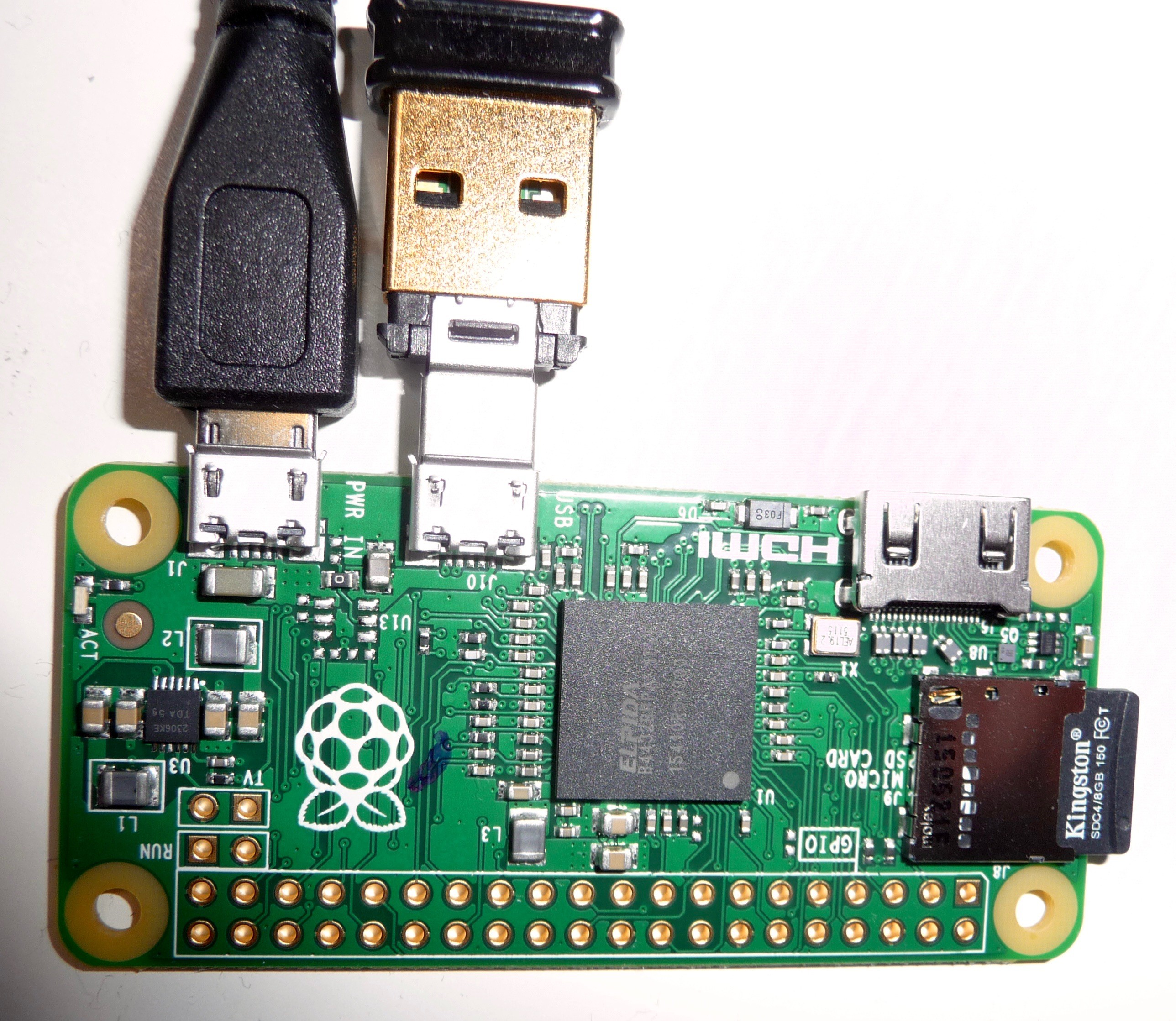
By the way, this is what the Pi Zero looks like with the power connection and the mini USB WiFi adapter:
![]()
While the WiFi adapter almost vanishes inside a standard USB port, it still looks huge connected to the Pi Zero even with the tiny USB to USB-2-go adapter. This single board computer is really small... I like it! :)
Slow software progress
Due to my other activities in the last few days, the software development has suffered.
I've started with coding, but did not make much progress so far. The good thing is, that the structure and details become clearer as I go along. Just like carving out a nice statue out of a block of stone.
So nothing much to show here.
I've also done some additional image processing tests and played around with different options and operations of the "graphicsmagick" software. Testing taking a full HD resolution greyscale image (1920 by 1080 pixels) from the C920 webcam in PNG format, I stumbled across another potential pitfall for the image processing: errors in the PNG to TIFF format conversion.
Here is what one of the PNG files originally looked line (I had to export it to JPG as the PNG was bigger than the allowed 3MB):
![]()
After just performing the PNG to TIFF conversion that is needed in order to get a valid input format for the tesseract OCR software, the result of the conversion looked like this:
![]()
Needless to say, this does not work at all for a proper OCR conversion. I also tested the same image size and camera for a normal colour image, with the same result.
Since the earlier tests did provide properly converted images, I guess this may have something to do with the additional "delay" and "skip frames" options I tried for "fswebcam". Strange nonetheless, as the default image looks pretty normal.
Why can't the standard image processing be more reliable? :(
A new idea - sort of
Since the basic image quality is really important for the standard OCR processing, I've thought about different options for improving just that.
Software optimisations aside, the best bet seems to be to use a different camera, with higher resolution, image stabilisation, autofocus etc. - all the nice features that most digital stills cameras already have, from simpler point-and-shoot cameras up to the big and expensive DSLRs.
So it might be an even better idea in the long run to look into using a not-to-big point-and-shoot camera instead of a webcam.
The "TextEye" could be a camera add-on, similar to an extended battery/grip unit like the ones which are available for most DSLR cameras.
If the signal for the full button press that the camera needs in order to take a picture can be tapped into, that could act as as start signal for the image conversion, OCR processing and speech output. On cameras with a "hot shoe" slot or similar connection for an external flash, this signal should be available through the flash connector.
The tricky part is to access the memory card or internal memory of the camera from the Raspberry Pi. Ideally, the camera should take the picture and save it to an SD card, and the Pi should then access the card and read the most recent image file, treating the camera's SD card reader/writer as an external, mounted file system.
From there the picture could be converted and saved to the default SD card of the Pi (with a constant name), then OCR processed and text-to-speech converted just like with the original design.
With an additional hack into the camera's on/off switch, the TextEye module (with integrated speaker) could be booted up and shut down with the same button automatically. Not really necessary, but a nice addition.
The additional battery might also be omitted if it would be possible to tap into the power from the camera, although this would probably shorten the possible overall operation time quite substantially - small and medium sized cameras don't have very powerful or long lasting batteries to start with. So I guess it's better to leave the additional battery in there, though it might be smaller as it does not have to power the camera.
For the moment, I'll continue to work on the original design for this project, but I will definitely look into this option as well. Apart from the camera and the basic camera connection, the rest of the hardware and software is the same for this new design. Custom cases are needed in both versions, and the second design option would also need changes or adapters for different cameras. But mainly the components have to be placed a little differently for a nice fit in both cases.
So the main question is: can a standard SD card reader/writer inside a digital camera be hacked properly in order to achieve this?
If anyone has already done that or can provide links to a similar project, I'd appreciate it.
This design variation may not solve all of the image processing problems, but it should provide a much better starting point and image quality.
TextEye: Raspberry Pi (Zero) Mobile Textreader
A mobile text scanner/reader for people with severe visual impairments