Annelle Rigsby
-
Links to Similar Projects
10/18/2019 at 14:00 • 0 commentsTo see clever implementation of music using rotary dial phones, follow the links in this document: https://apinventions.wordpress.com/wonderfoon/
-
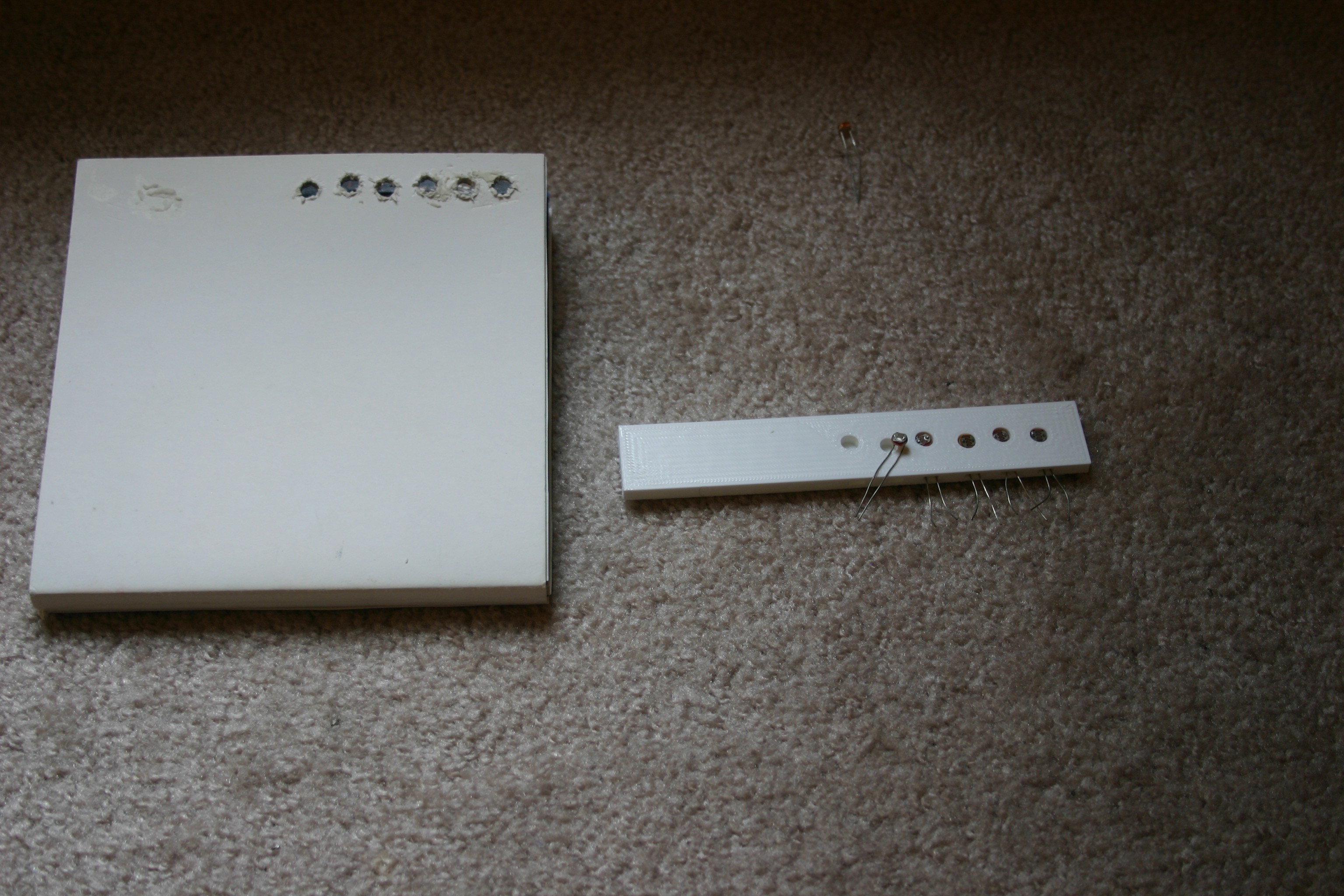
Verify Photo Resistor Output
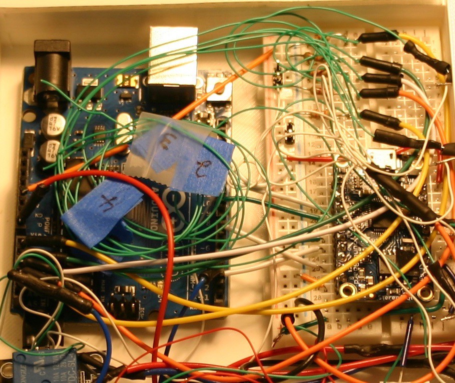
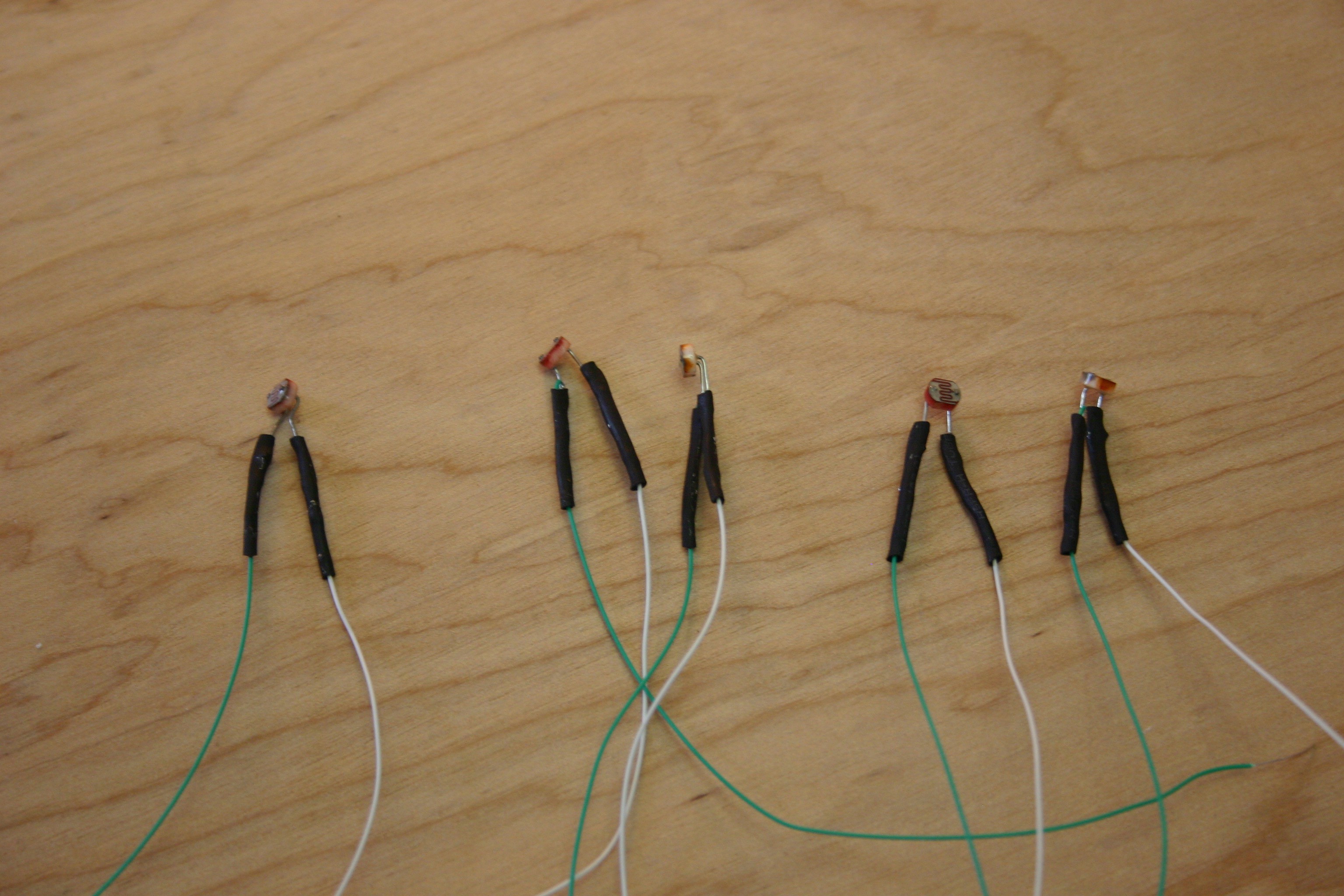
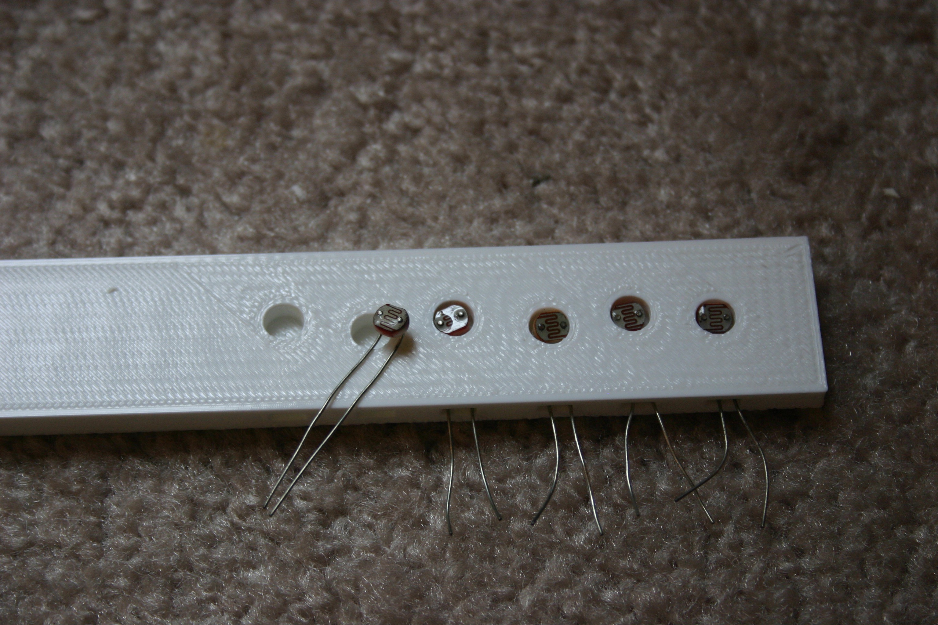
10/01/2018 at 17:56 • 0 commentsHoles in the board book that are misaligned or not clean can impact the output of the photo resistor. To verify the voltage received on the analog input pins of the Arduino, I attached wire wrap wire to the resistor junction that connects to the analog input pins. I labeled the wires (1 through 5) as shown below.
![]()
I brought these wires out (as well as a ground connection) and placed the board book on the electronic housing. In normal room lighting, I opened the book to each page and recorded the voltage on each input pin. The "dark" readings were about two volts (light leaks in from many places). The "page open" readings were 3.5 volts or higher. Pages deeper in (less hole space for light to travel through) read a little higher. If the room was lighter, the readings were higher.
Because zero to five volts on the Arduino results in readings of 0 to 1023, the open readings would correspond to a value of about 700. I didn't want to cut it too close, so I used 600 as the number to indicate a page was receiving light.
-
Adding Photos and Text to the Board Book
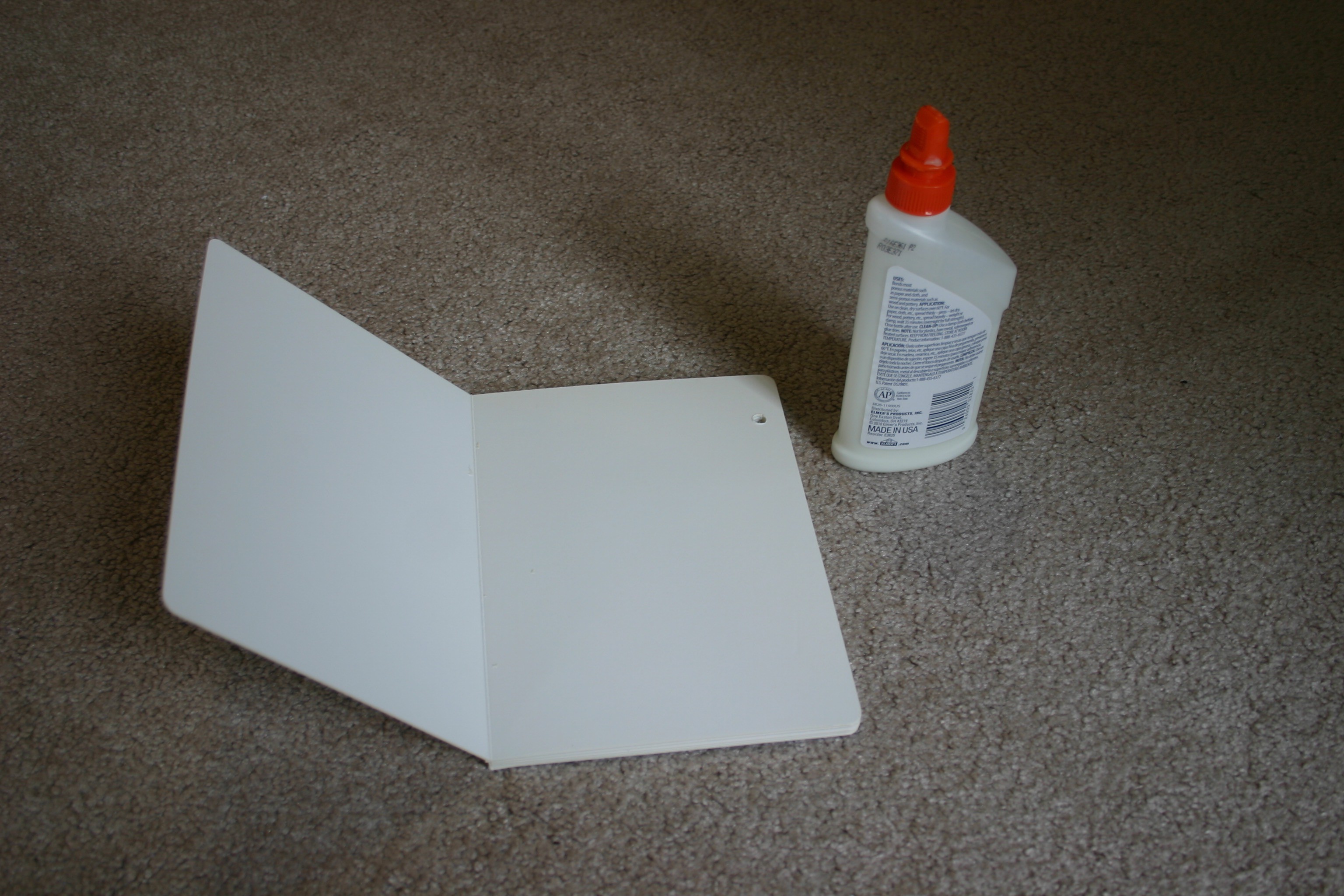
10/01/2018 at 17:32 • 0 commentsAfter selecting and sizing the text and photos for the book, the pages should be printed using photo paper (the paper needs to be stiff and durable to prevent wrinkling during the glue process). I use ordinary white wood glue.
![]()
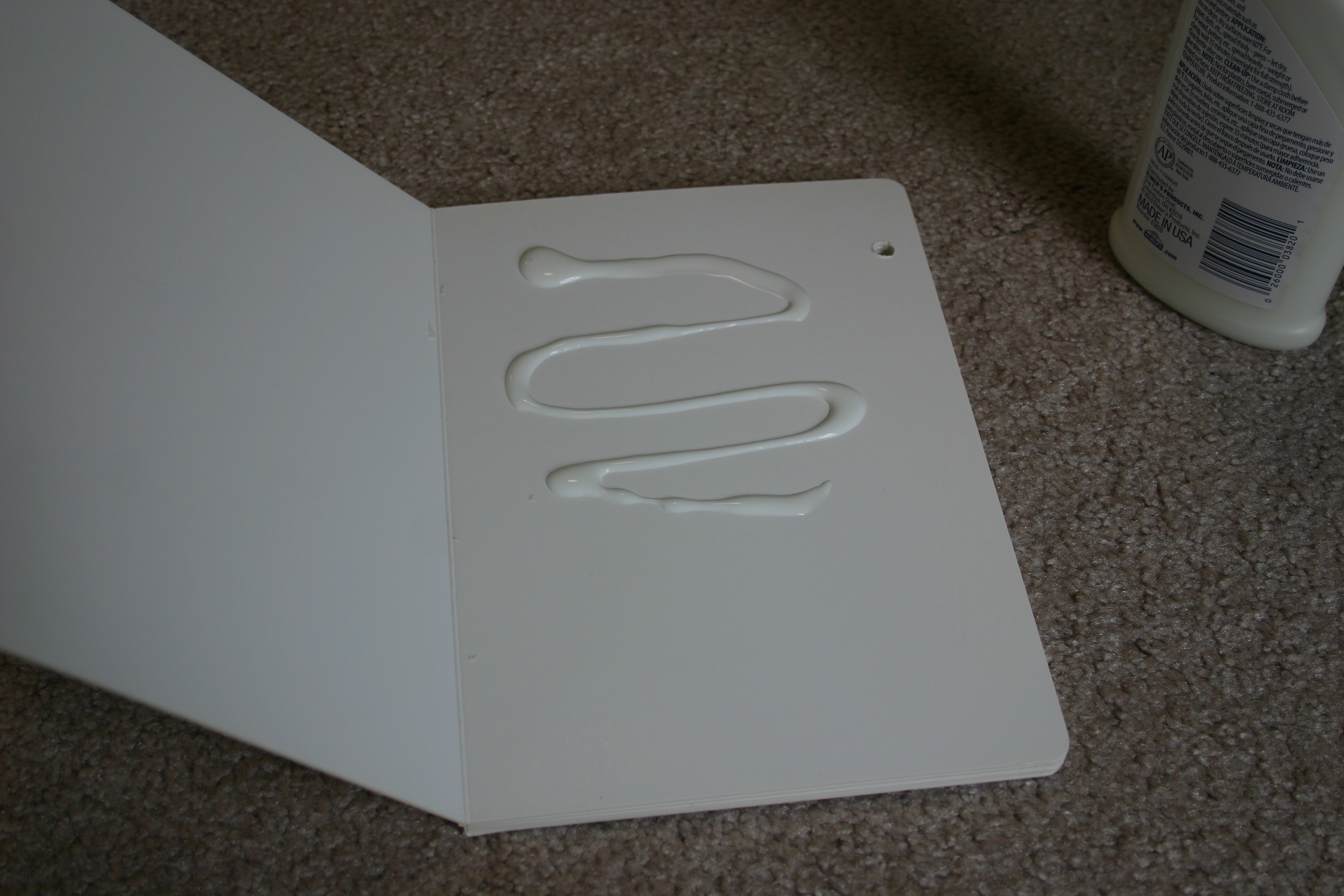
Spread the glue liberally on the page.
![]()
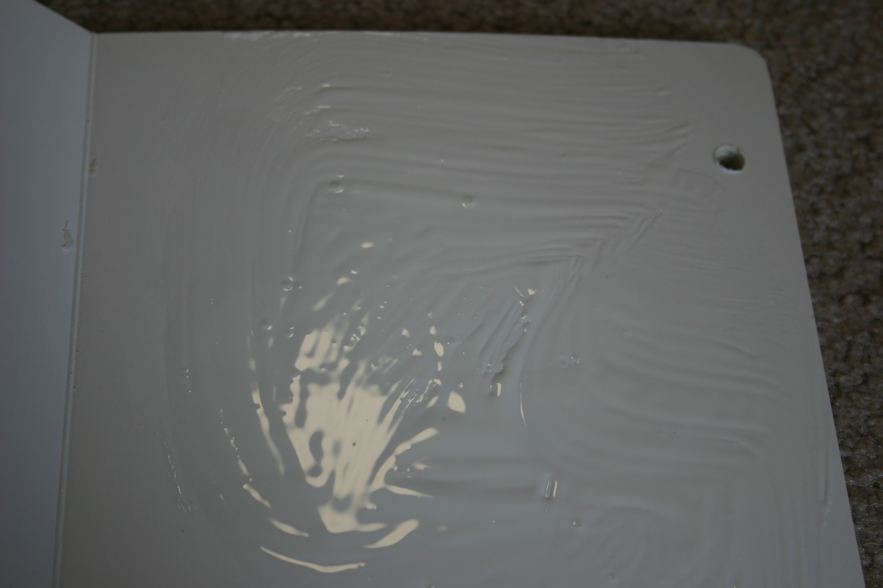
Using a paper towel or brush, spread the glue evenly.
![]()
Place the photo/text on the glue. Check for excess glue around the edges of the image. Wipe excess away if necessary. Wait until the glue has dried before attaching another image to another page; otherwise, pages may stick together.
-
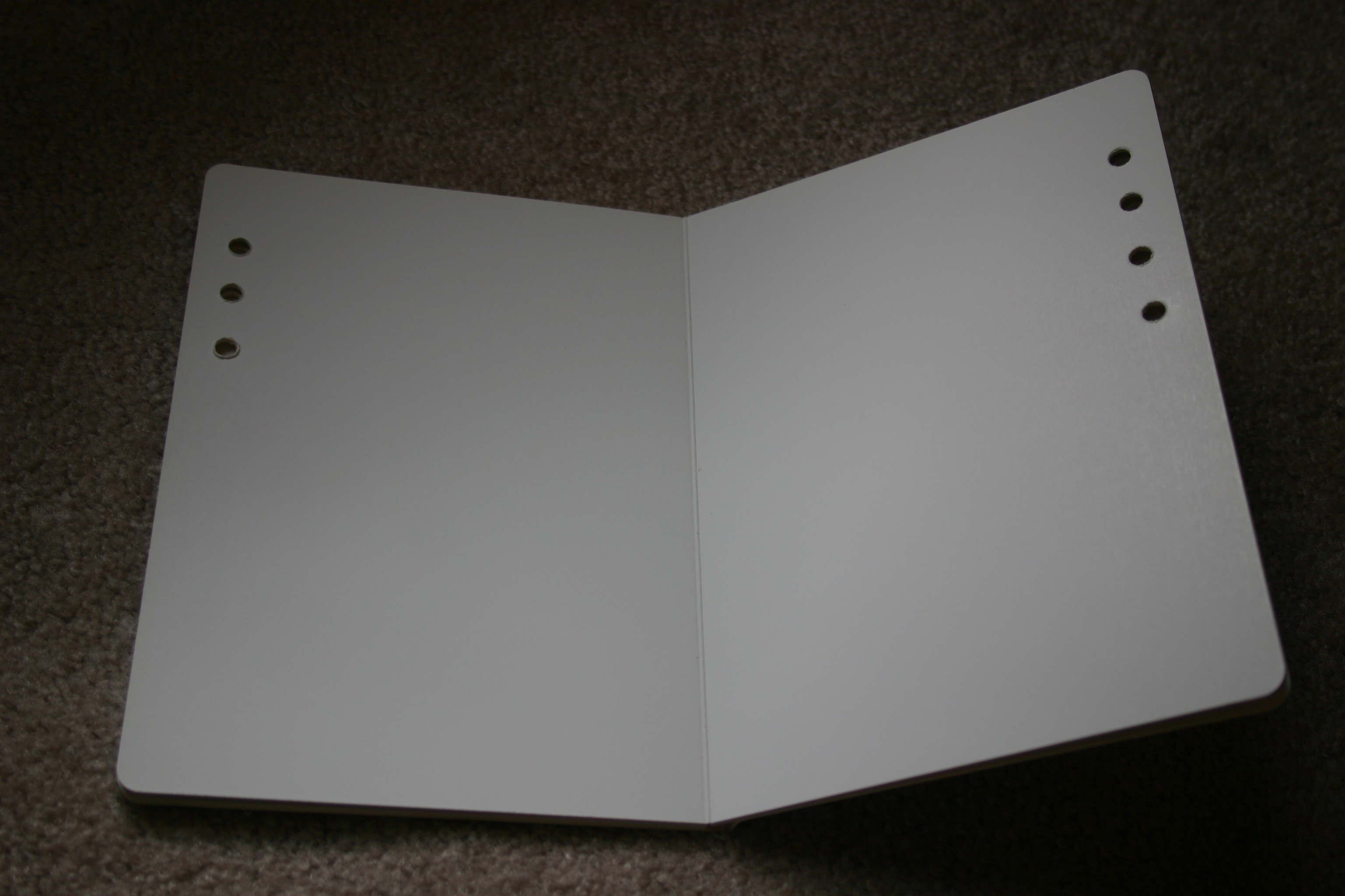
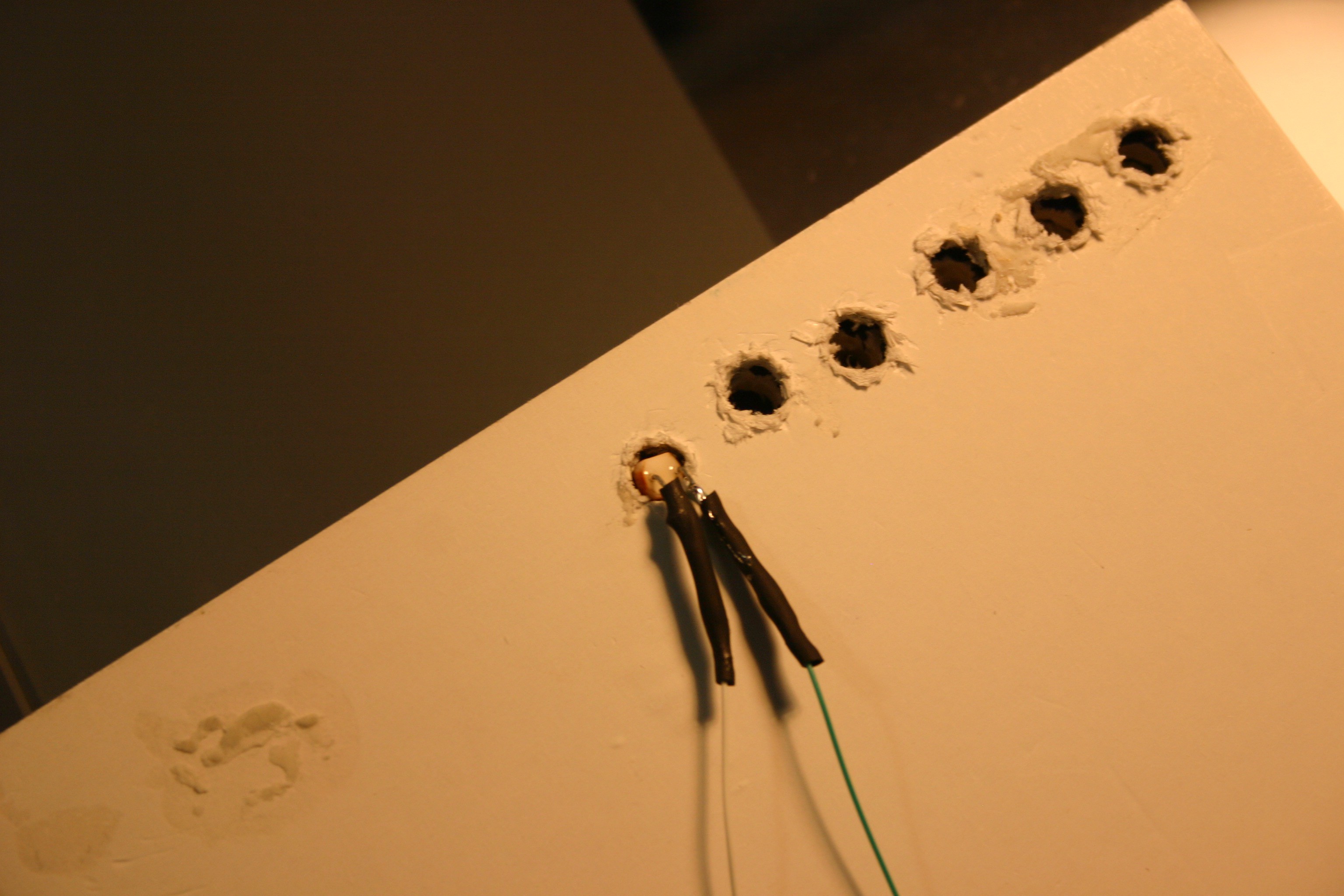
Making Holes in the Board Book
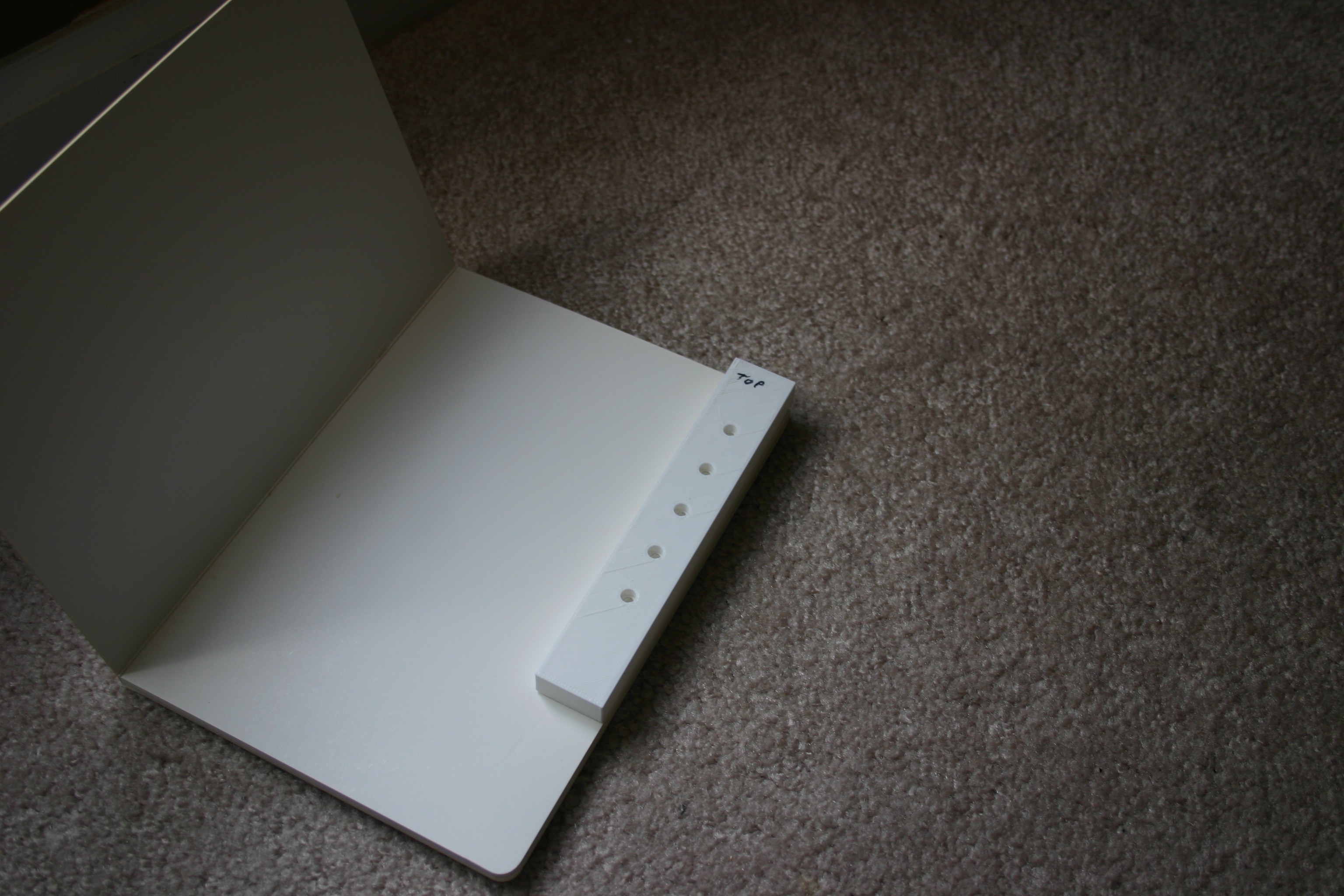
10/01/2018 at 17:05 • 0 commentsMaking clean holes in the correct spot for the photoresistors can be a challenge. I 3d printed a "punch jig" to make this process a bit easier. First, line up the the punch jig with the upper right corner of the page to be drilled.
![]()
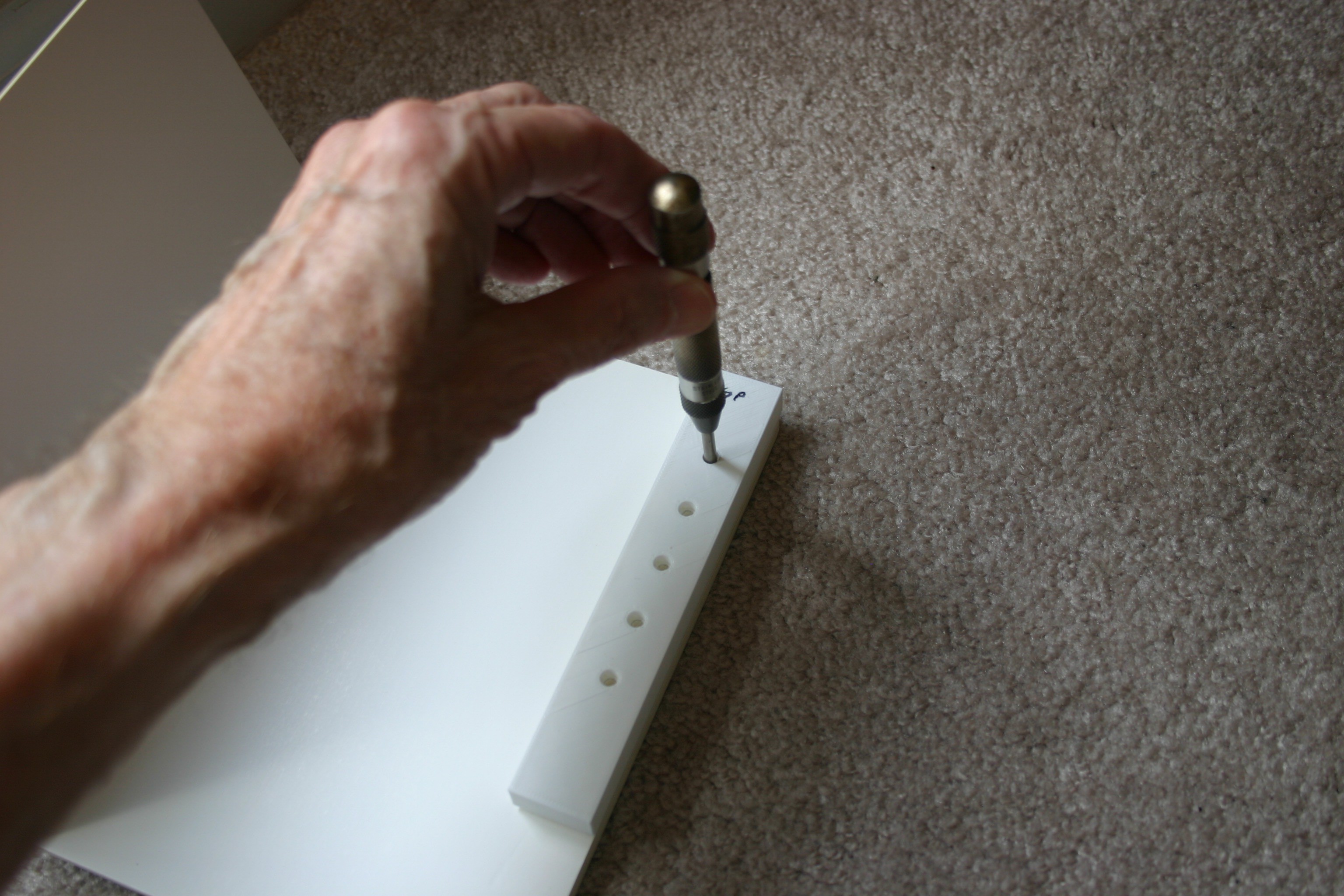
Use a drill punch to mark the place for the hole.
![]()
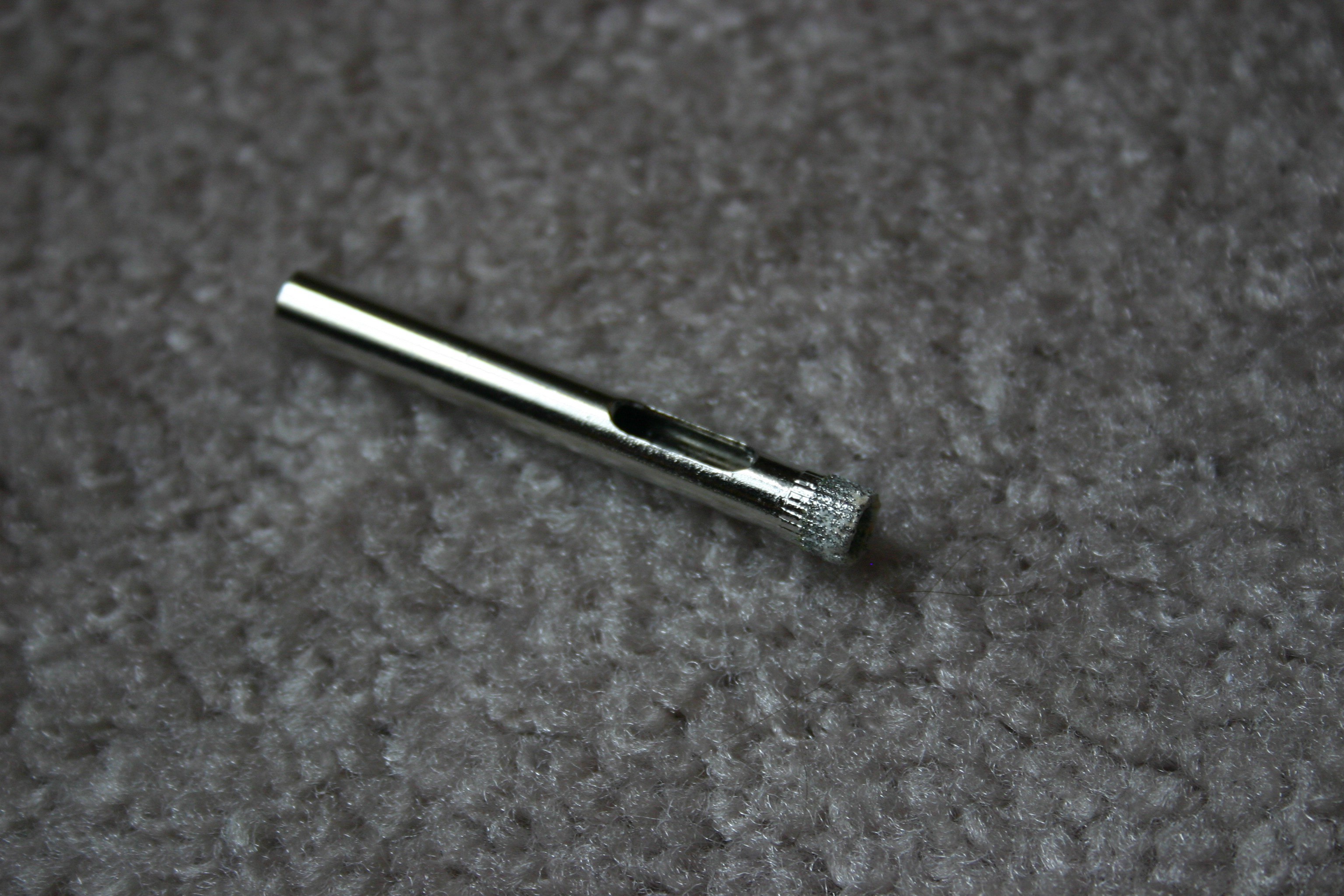
Use hollow core drill bits to create the hole.
![]()
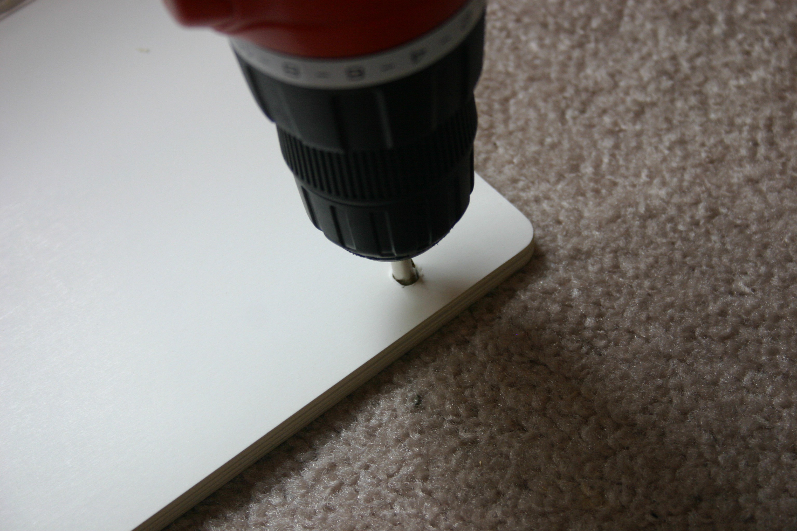
I had to gently start the hole with a normal drill bit, then use the hollow core bit.
![]()
The first hole goes through five pages, the second through four etc.
![]()
-
Recording Music
10/01/2018 at 14:02 • 0 commentsMusic has to be moved from a source to the Notable Board Book. For this example, and to be completely open source, I selected songs where the copyright had expired, then I played the keyboard and our daughter Tia provided the vocal accompaniment. My husband, Mike, recorded our efforts and transferred the music by the process shown below.
You would probably be safe using commercially produced music if: a) you purchased the music AND: b) you are using it for a loved one AND: c) it is not played publicly AND: d) it is not distributed or sold.
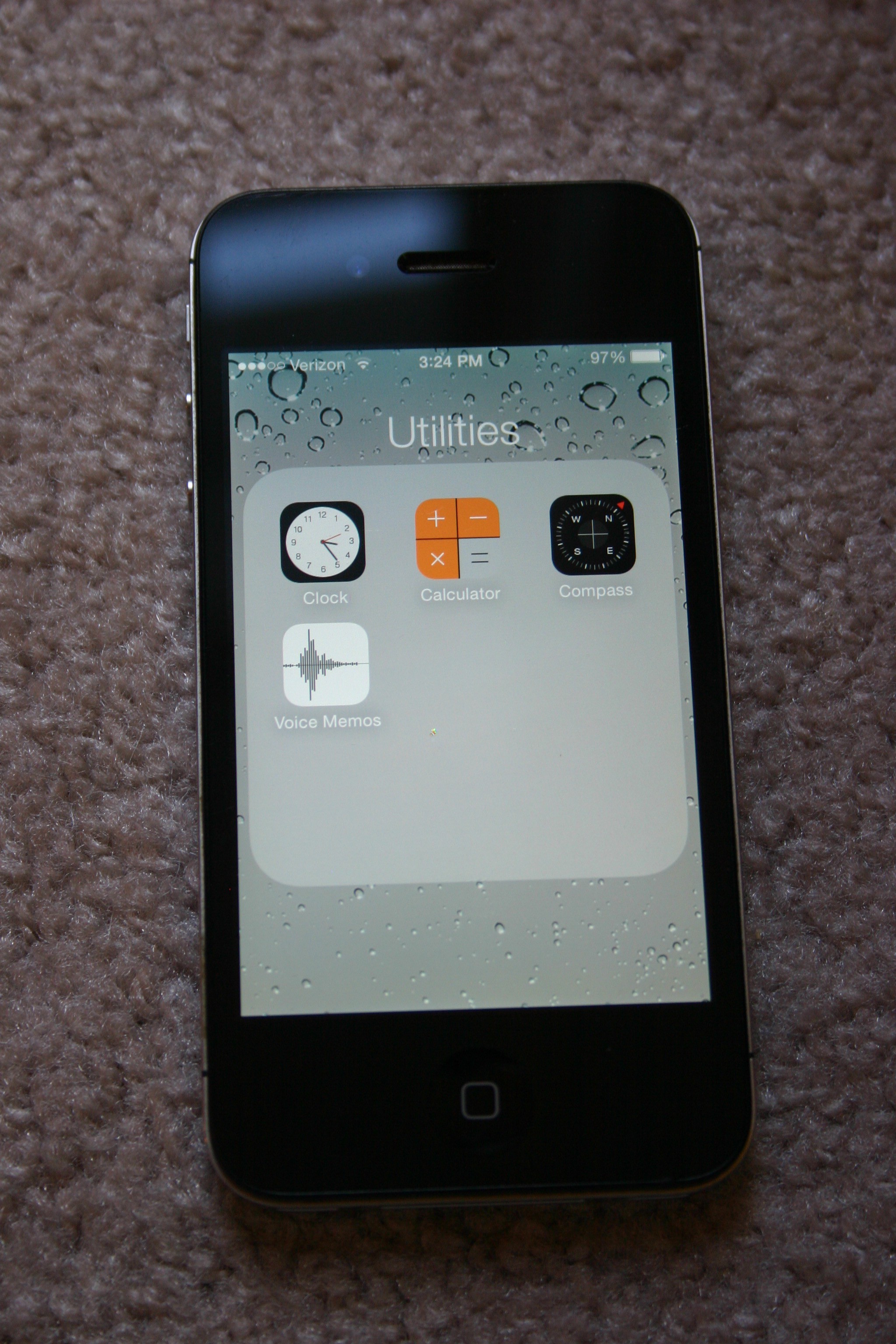
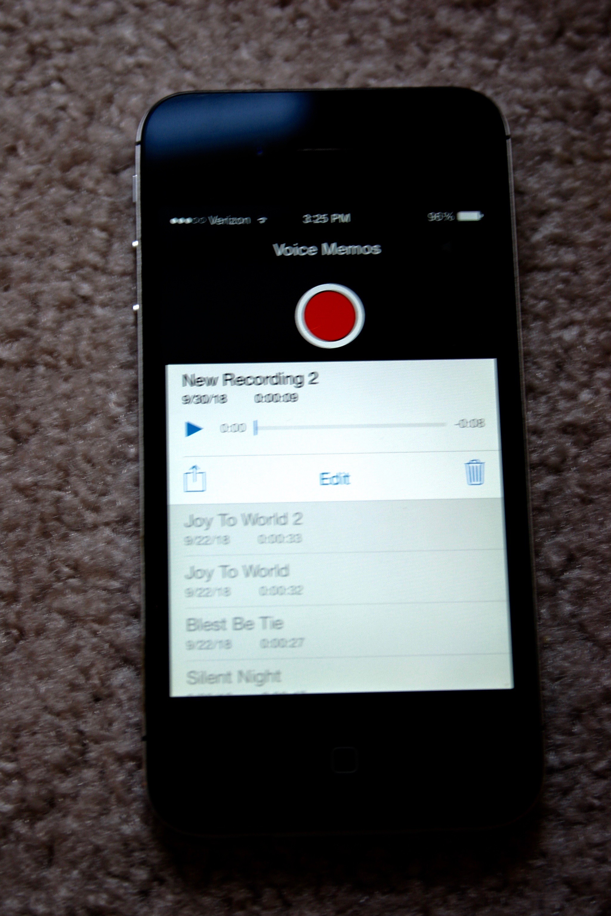
Not having access to serious recording equipment, we used an iPhone. Under "Utilities," select "Voice Memos."
![]()
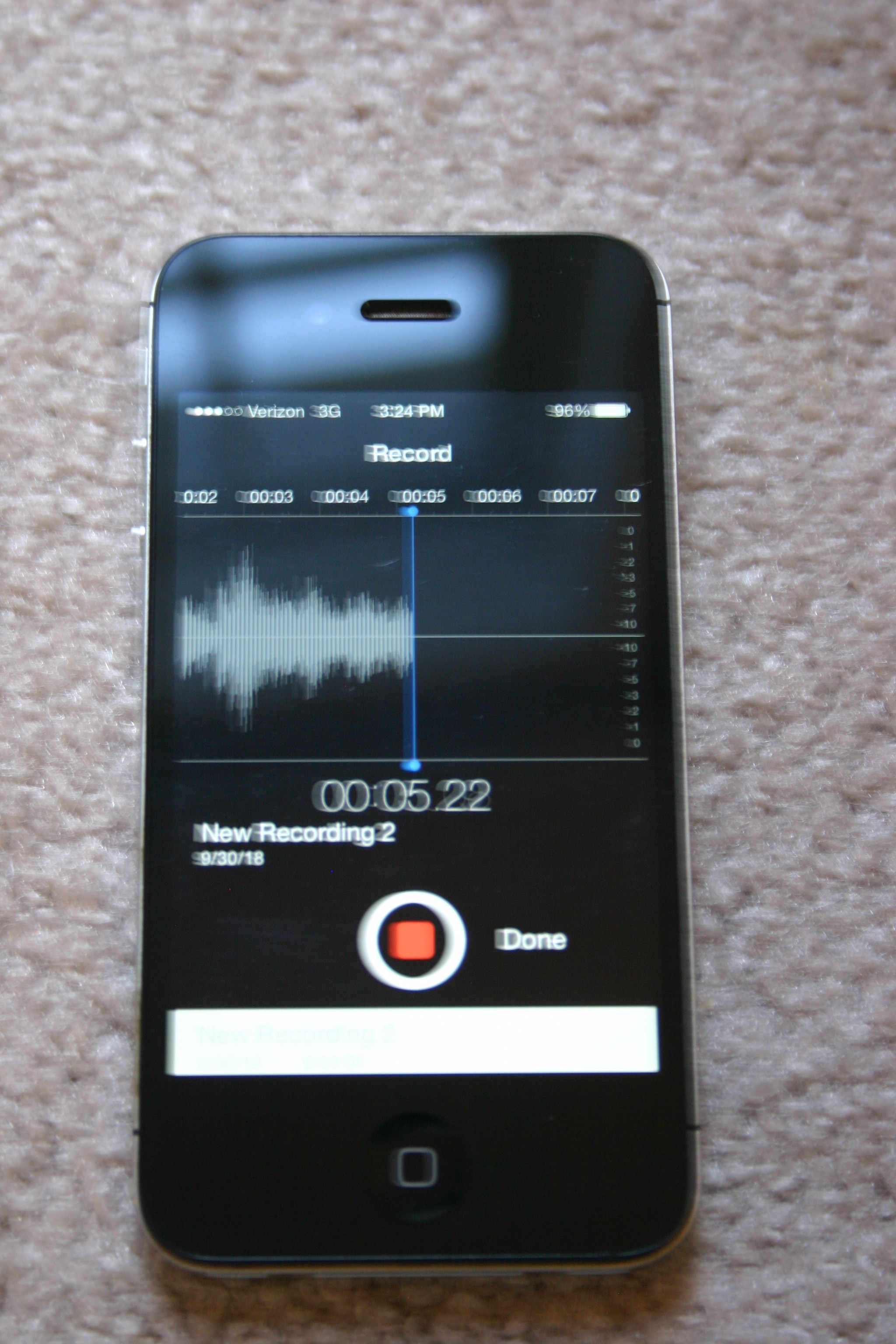
When you are ready to record, press the red record button.
![]()
Press the red button again when the song is complete. Press "Done."
![]()
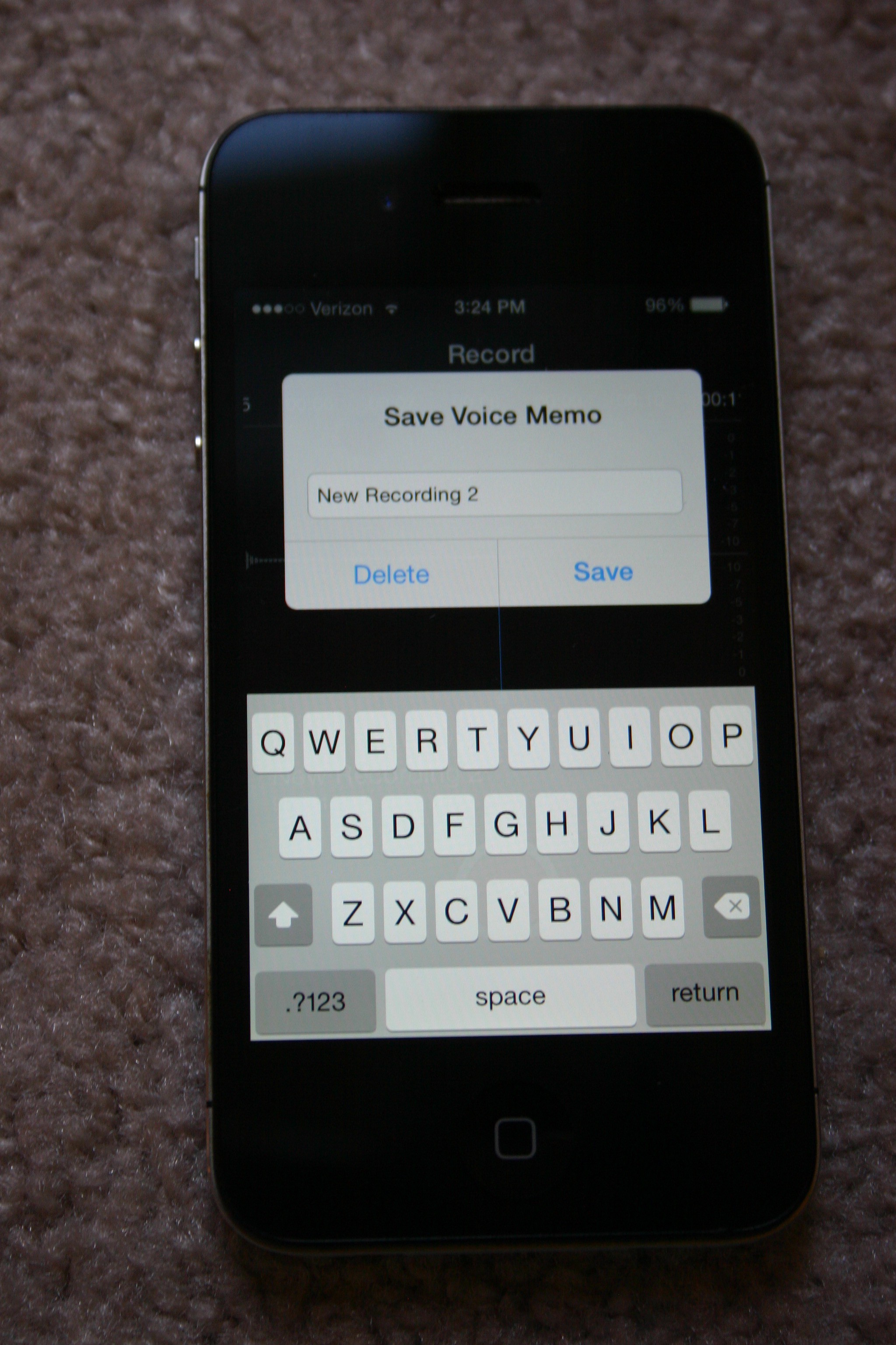
Press "Save" and open the file you just saved.
![]()
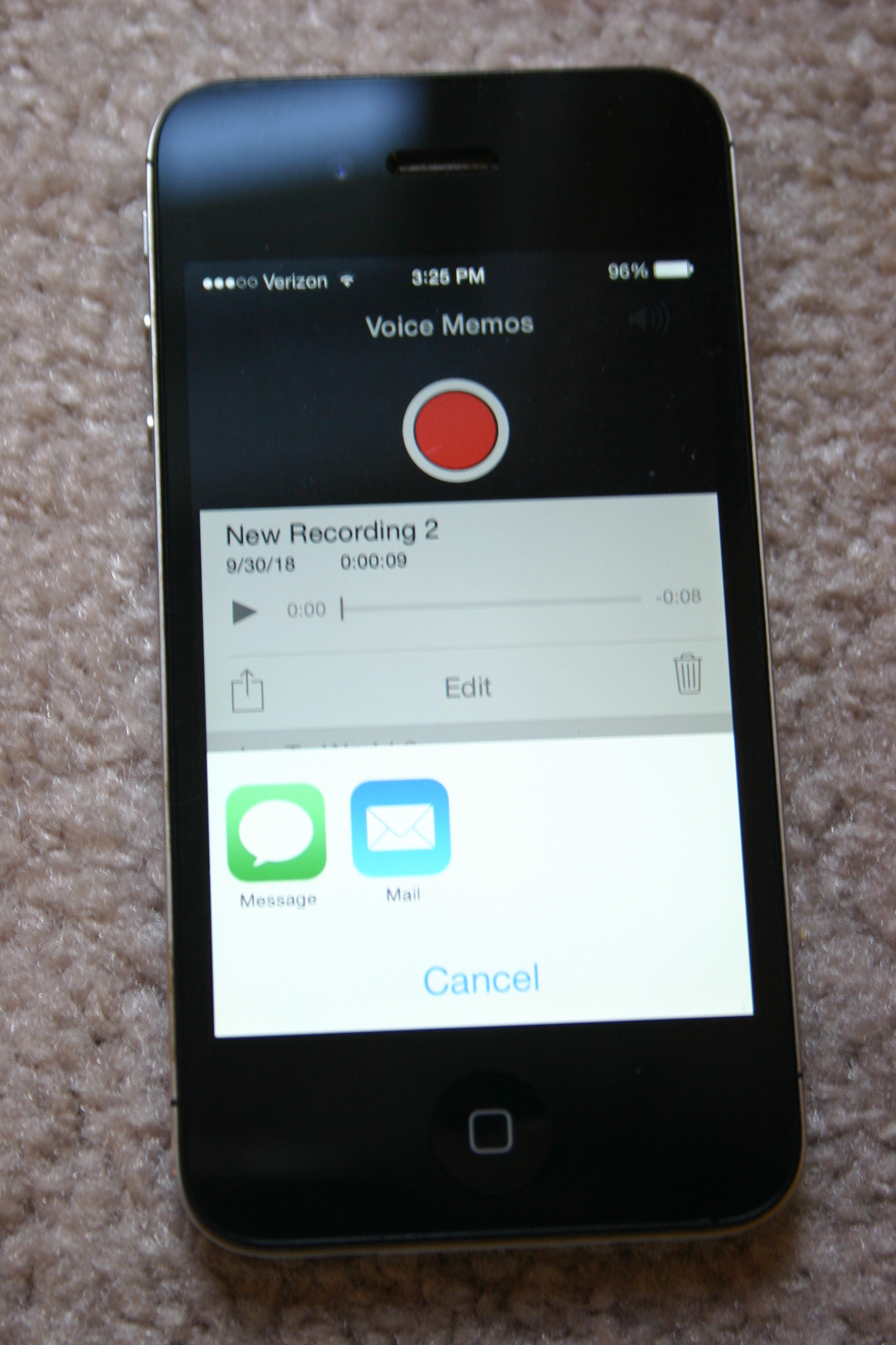
On the left side of the word "Edit" there is a small box with an arrow pointing upward. Select that box.
![]()
Select "Mail" and email the file to yourself.
Unfortunately, the file will arrive as a type "m4a." Go online and search for "convert m4a to ogg".
The Adafruit sound board has eleven control pins that correspond to software "slots" in memory. If the sound you just recorded is to be played when you pull the pin for slot #5 low, then the sound file should be labeled "T05.ogg".
Plug the Adafruit sound board into your computer and it will show up as a new USB key. Copy the .ogg files to the sound board. Eject the board and it is ready to play.
-
Functional Prototype
08/15/2018 at 21:03 • 0 commentsHere's what it works like:
I started by soldering wire wrap wire to the photo resistors, then shrink wrapping the ends to prevent shorting.
![]()
Then I inserted a photo resistor into the hole in the last page of the book.
![]()
Metal duct tape was used to secure the photo resistor in place (the sticky side of the tape does not conduct).
![]()
This was repeated for the five active holes.
![]()
It looks like this from the front side.
![]()
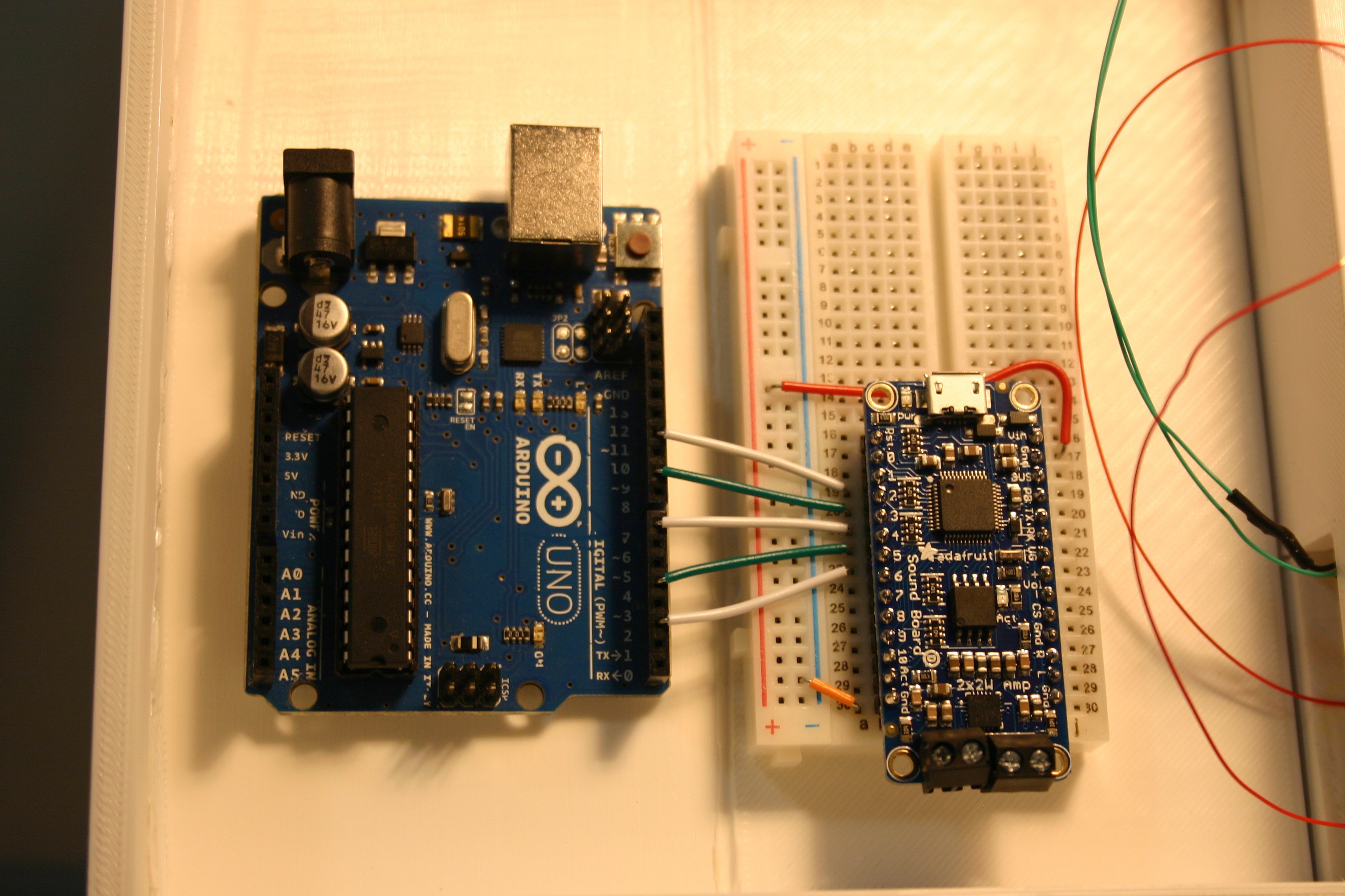
Using the schematic, the Arduino was connected to the Adafruit sound board.
![]()
![]()
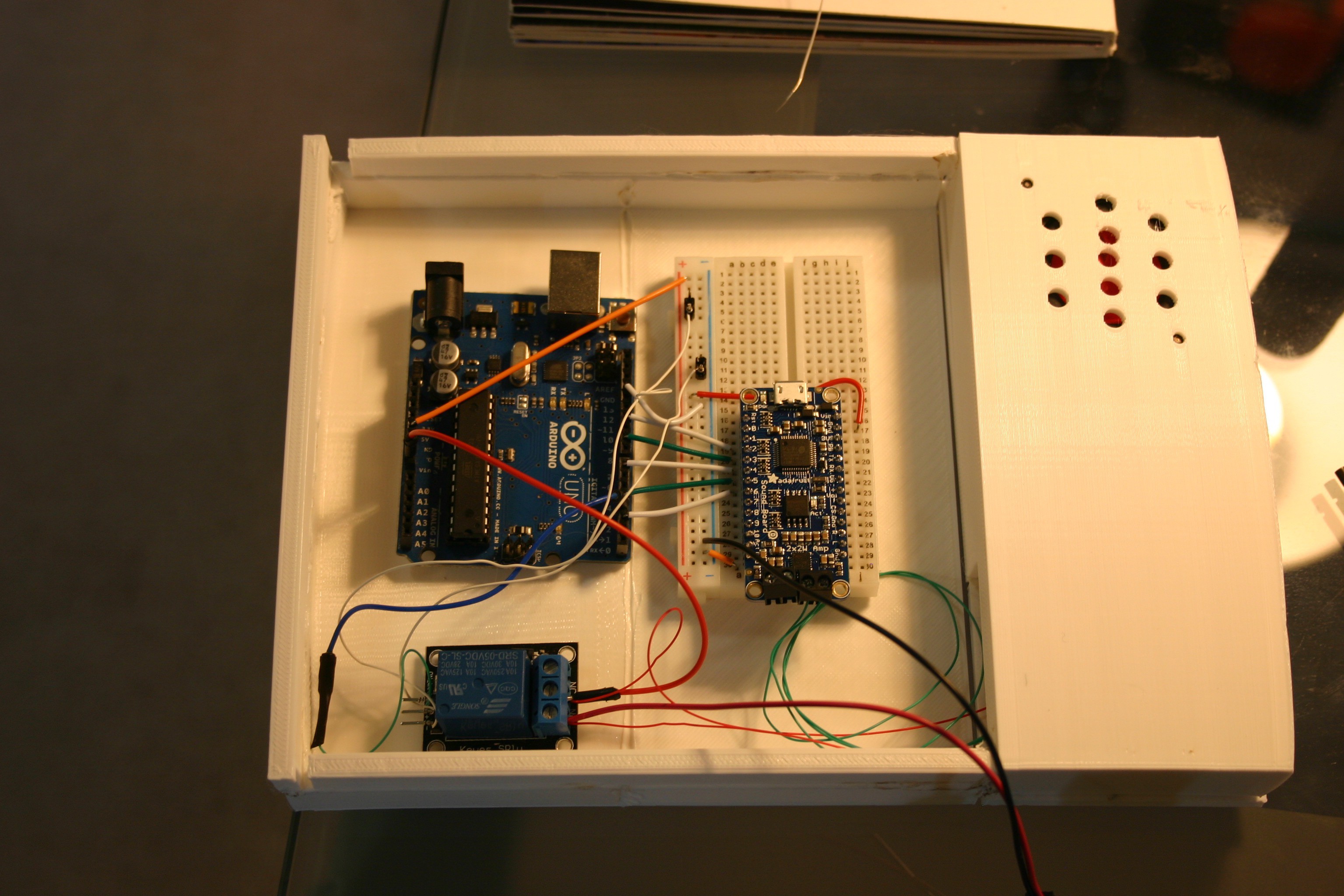
The relay and more Arduino connections are made.
![]()
Wires from the photo resistors (the board book) are attached.
![]()
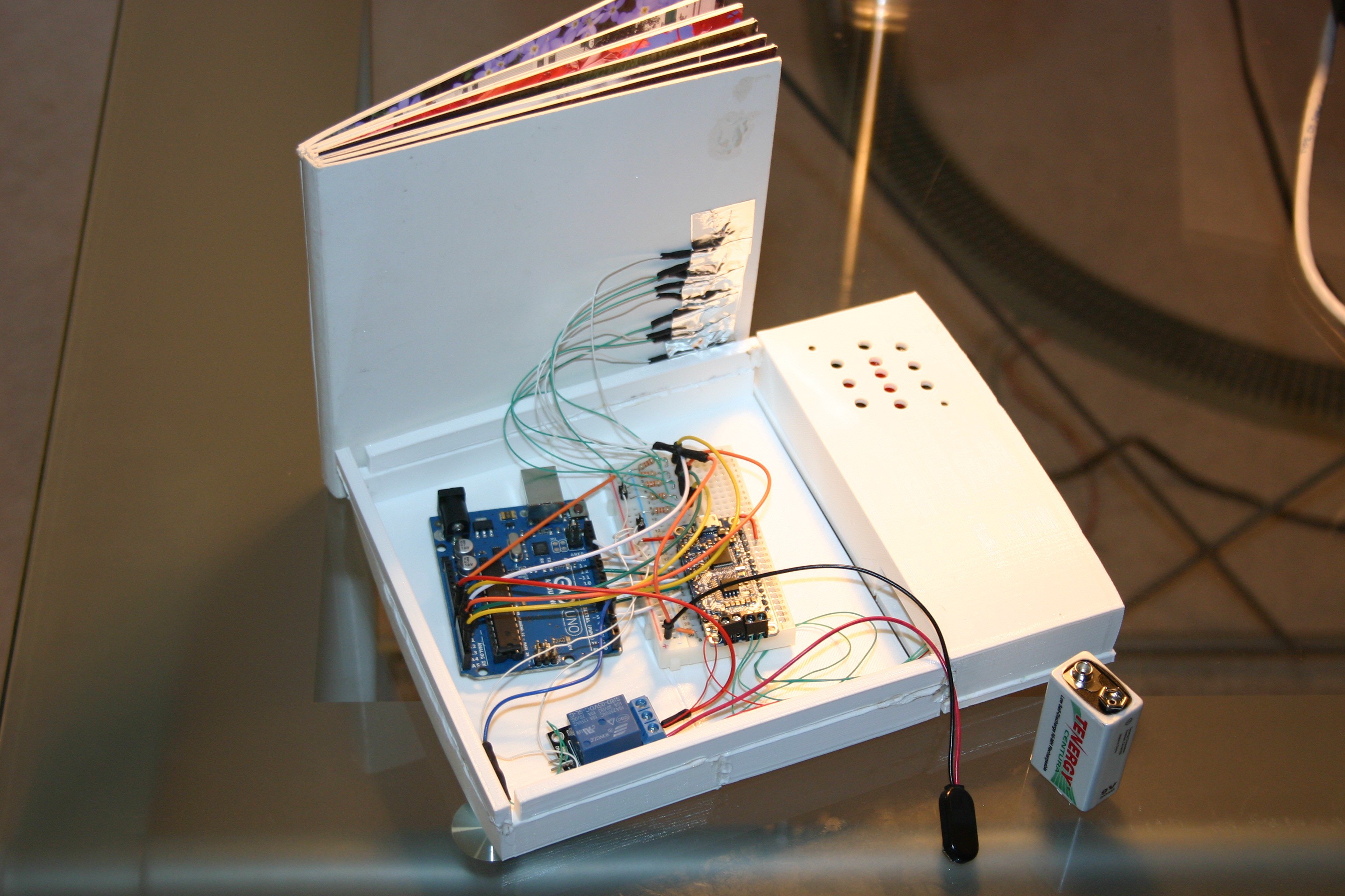
Using some sticky putty, the board book was attached to the case (I didn't want things too firmly attached until I have tested the book more completely).
![]()
The Arduino sketch for this is included in the files on this site.
-
Container
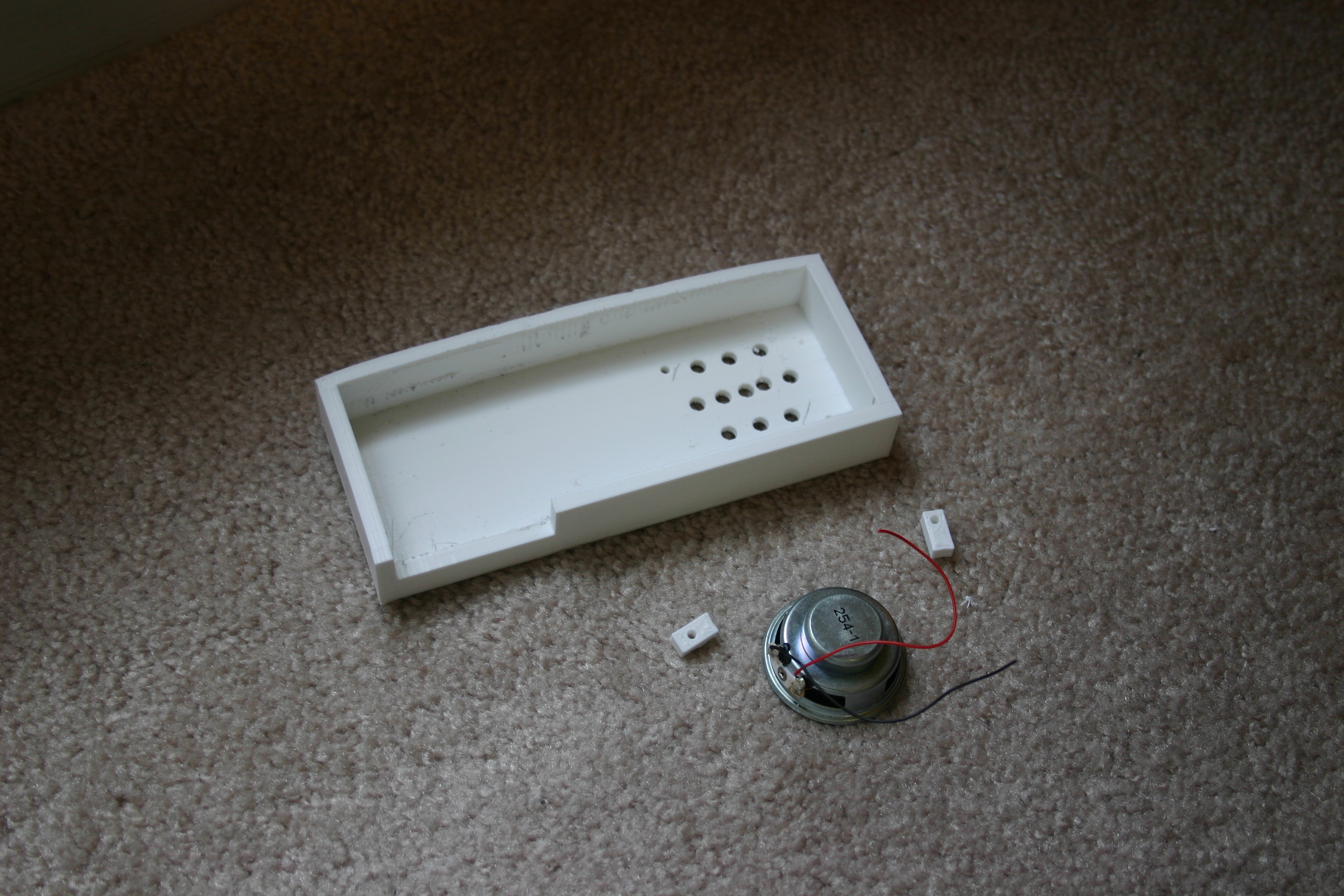
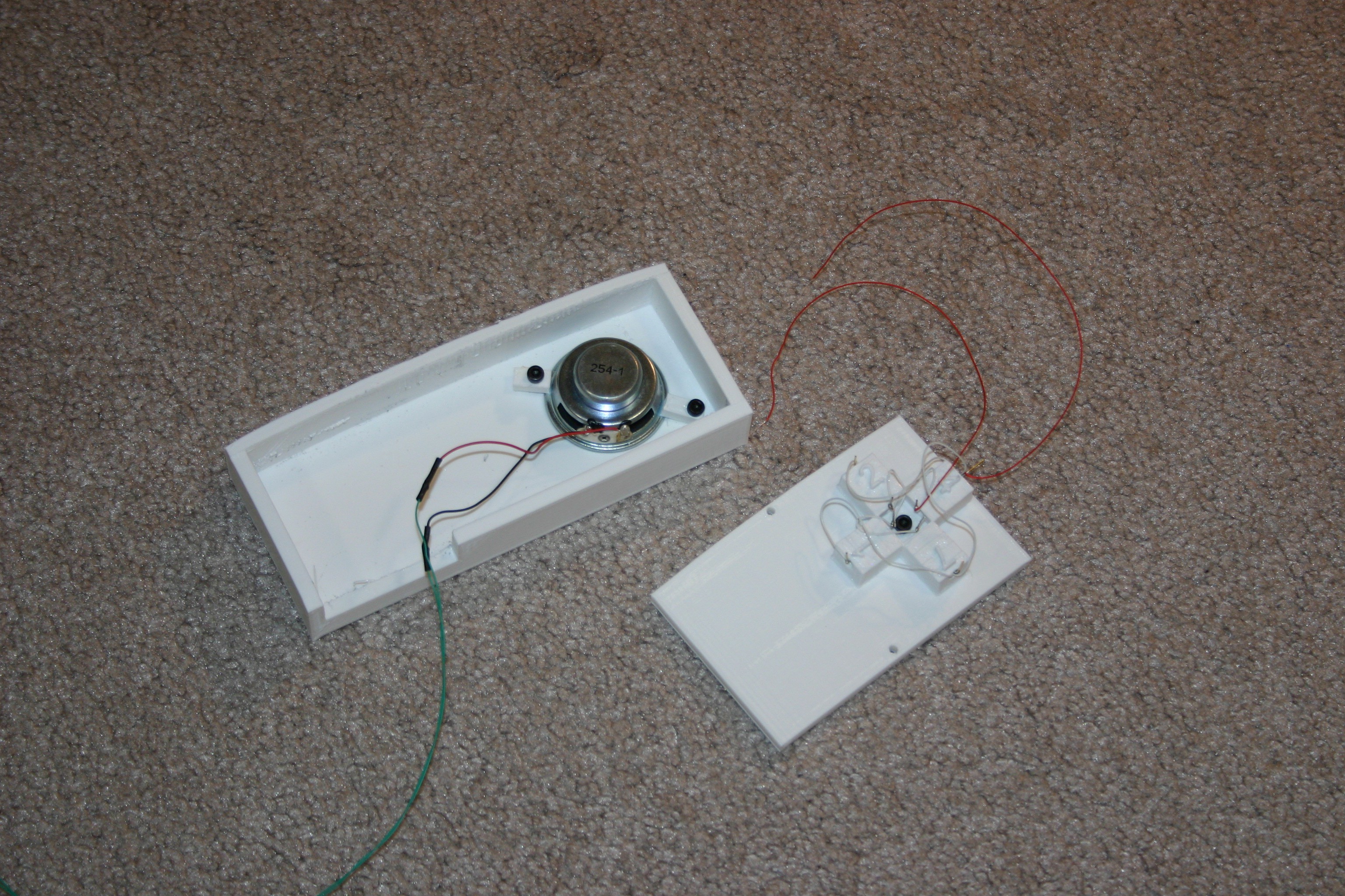
08/13/2018 at 19:16 • 0 commentsNow we start the process of combining the speaker, electronics and book. Here are the speaker, retainers and speaker enclosure.
![]()
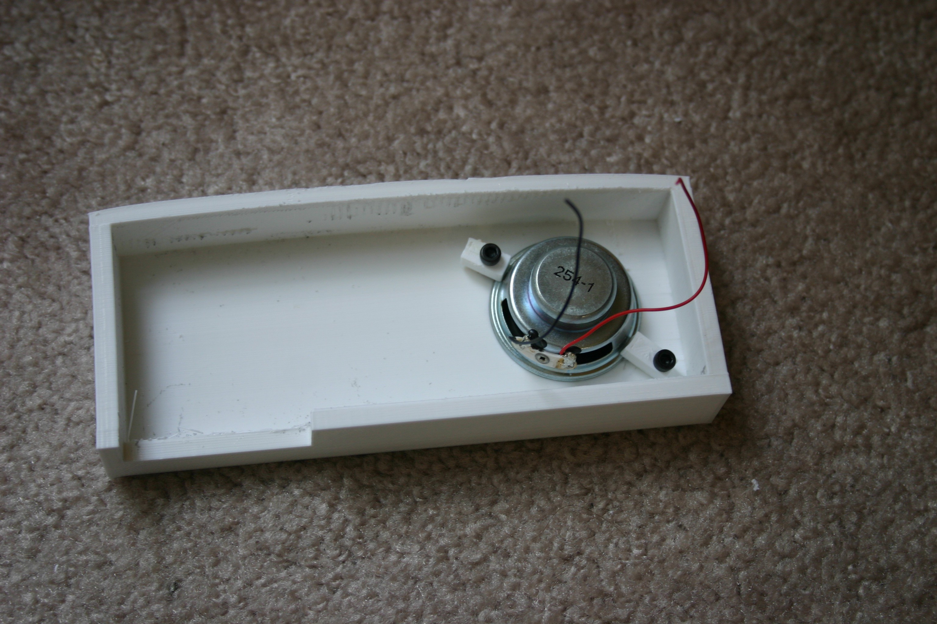
The speaker is mounted using 3mm x 8mm screws.
![]()
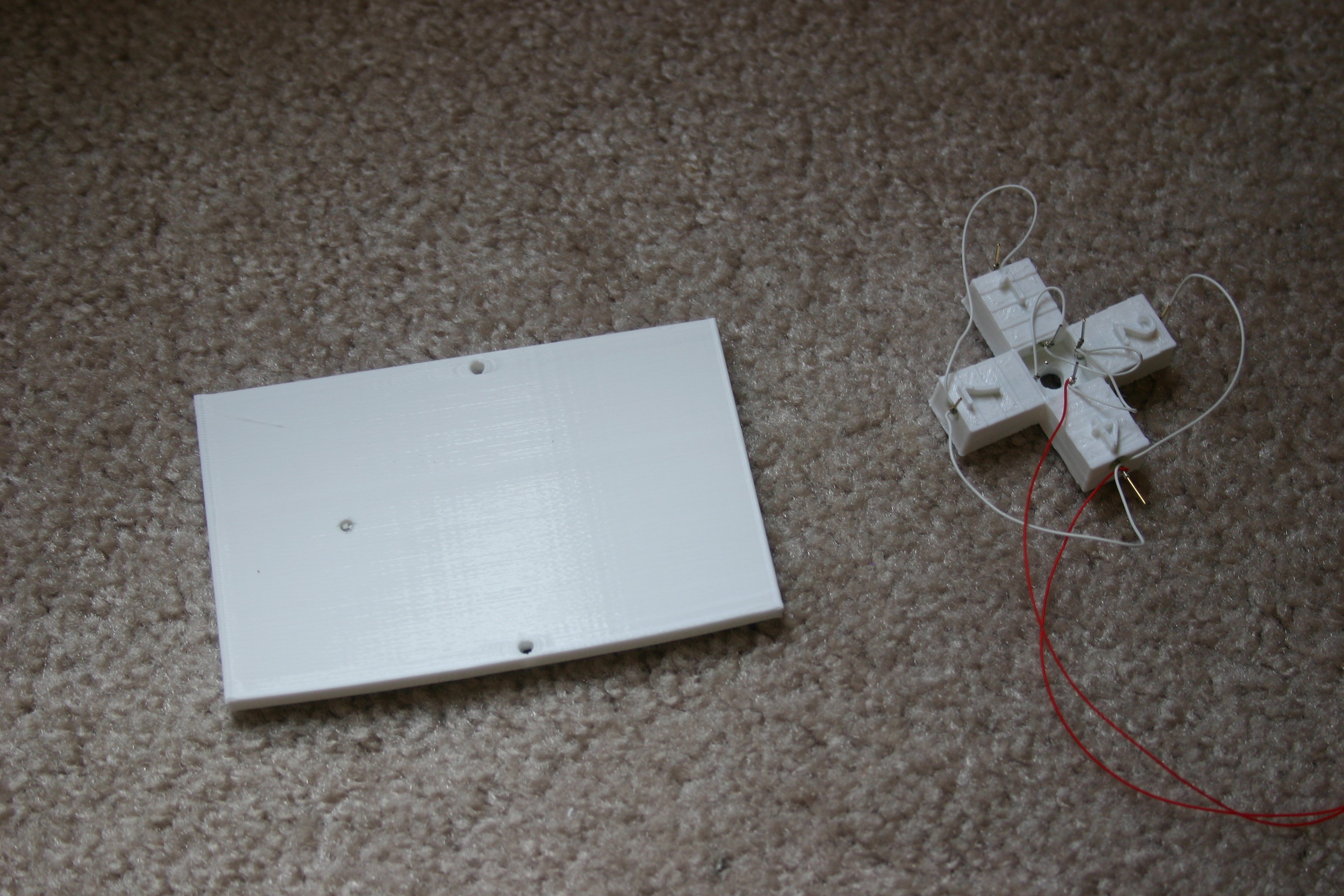
Next, gather the tilt switch and backplate.
![]()
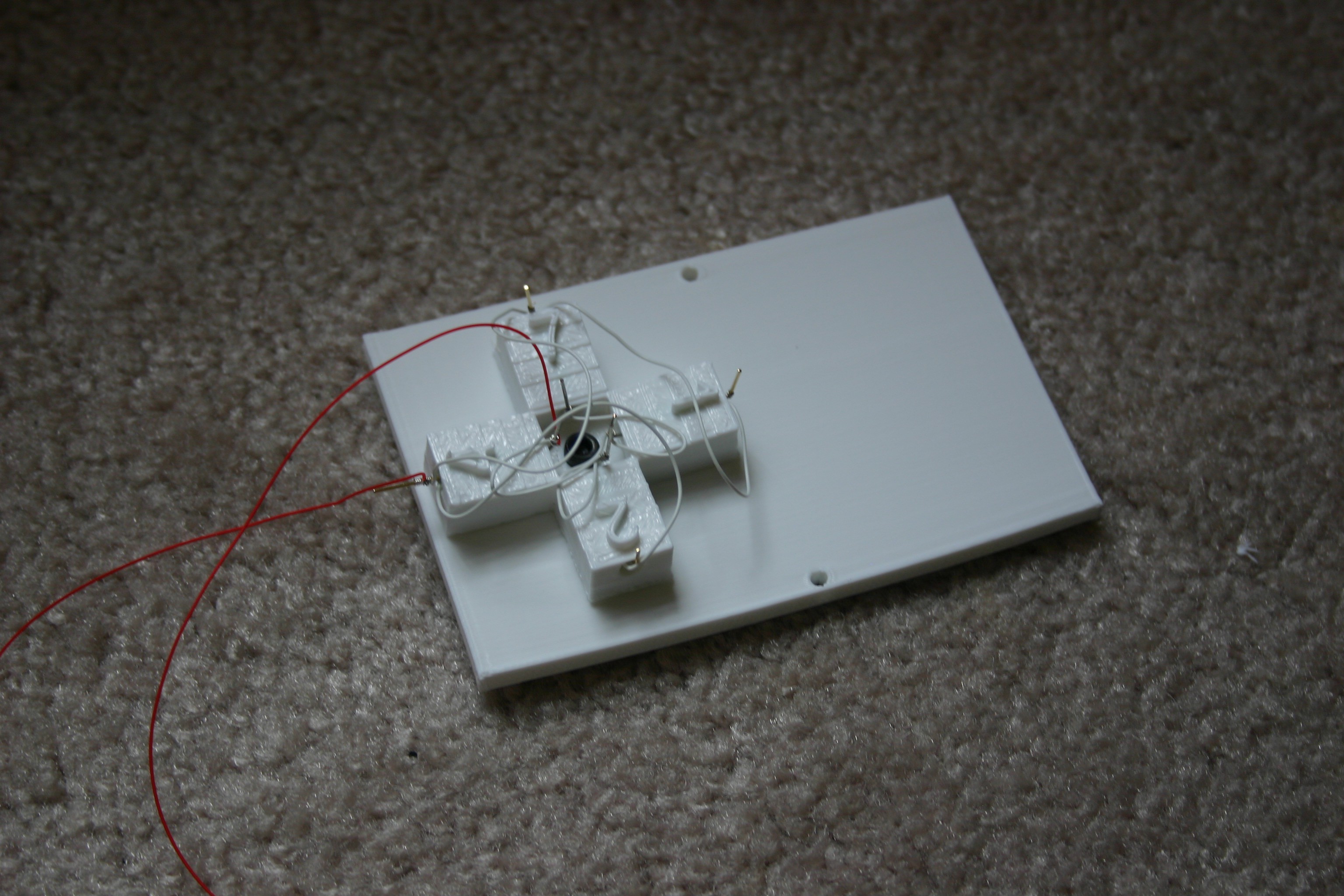
Fasten the tilt switch array to the backplate using a 3mm x 8mm screw.
![]()
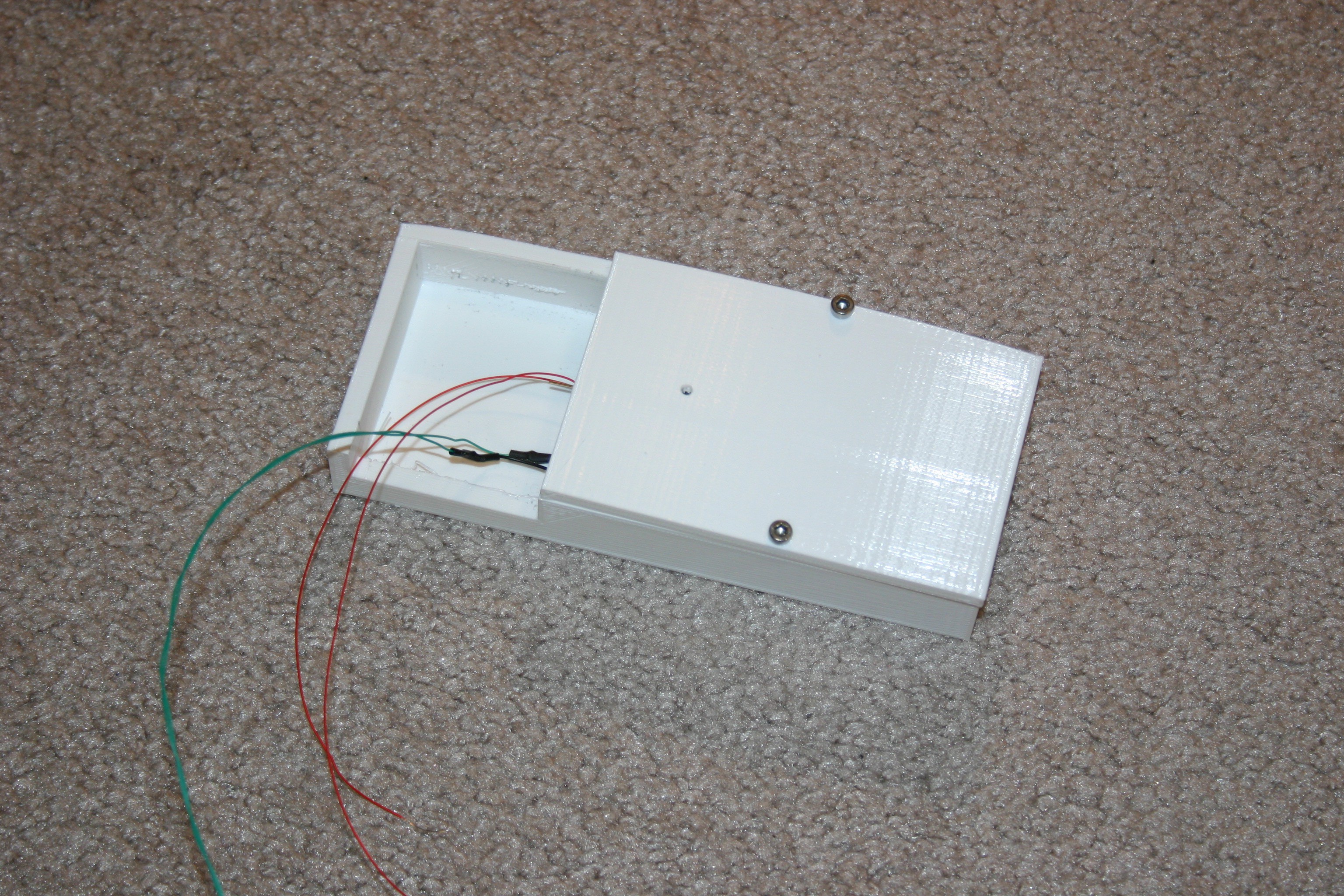
The tilt switch array is now ready to combine with the speaker housing.
![]()
Screwed together, they look like this.
![]()
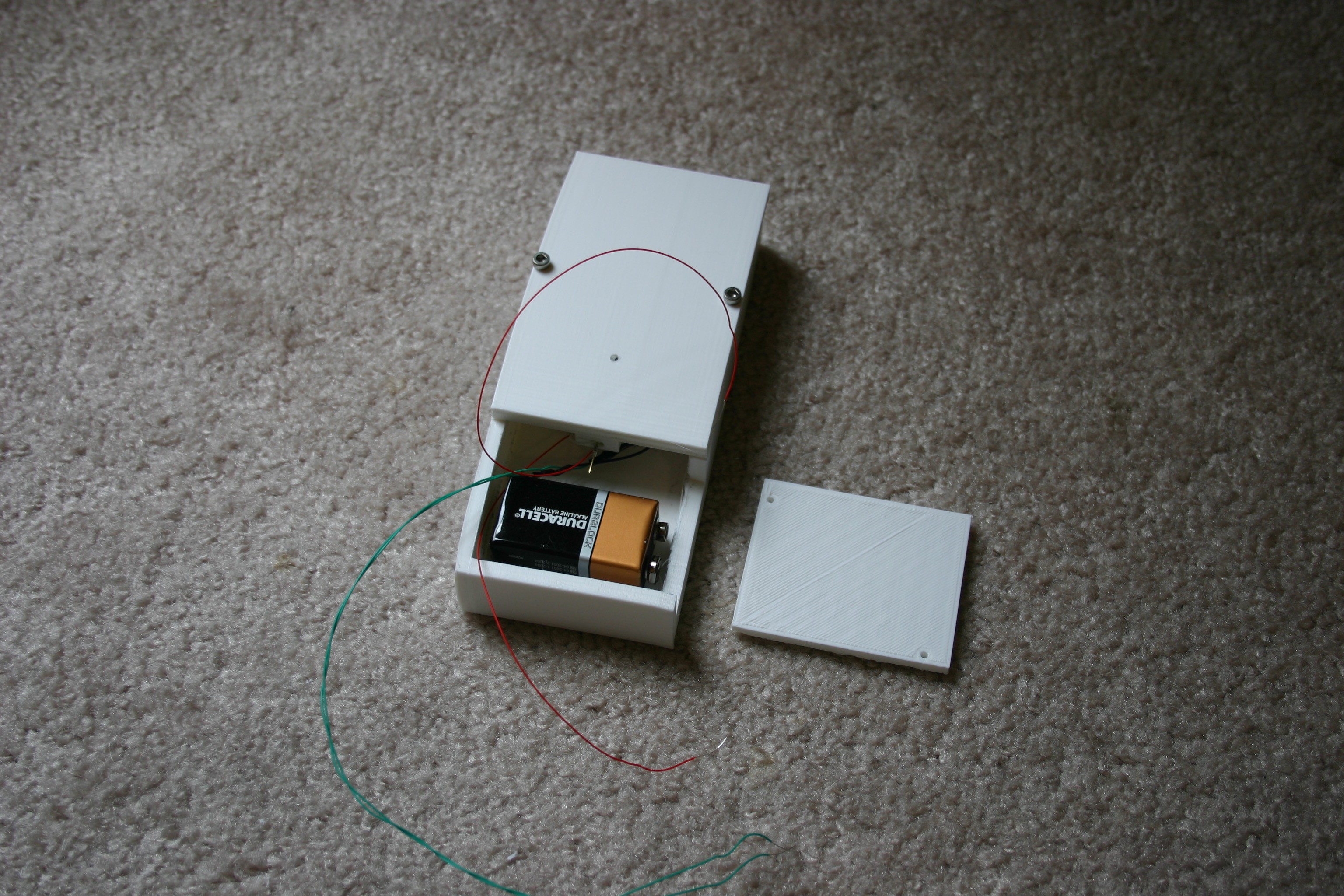
Gather the battery cover and speaker assembly.
![]()
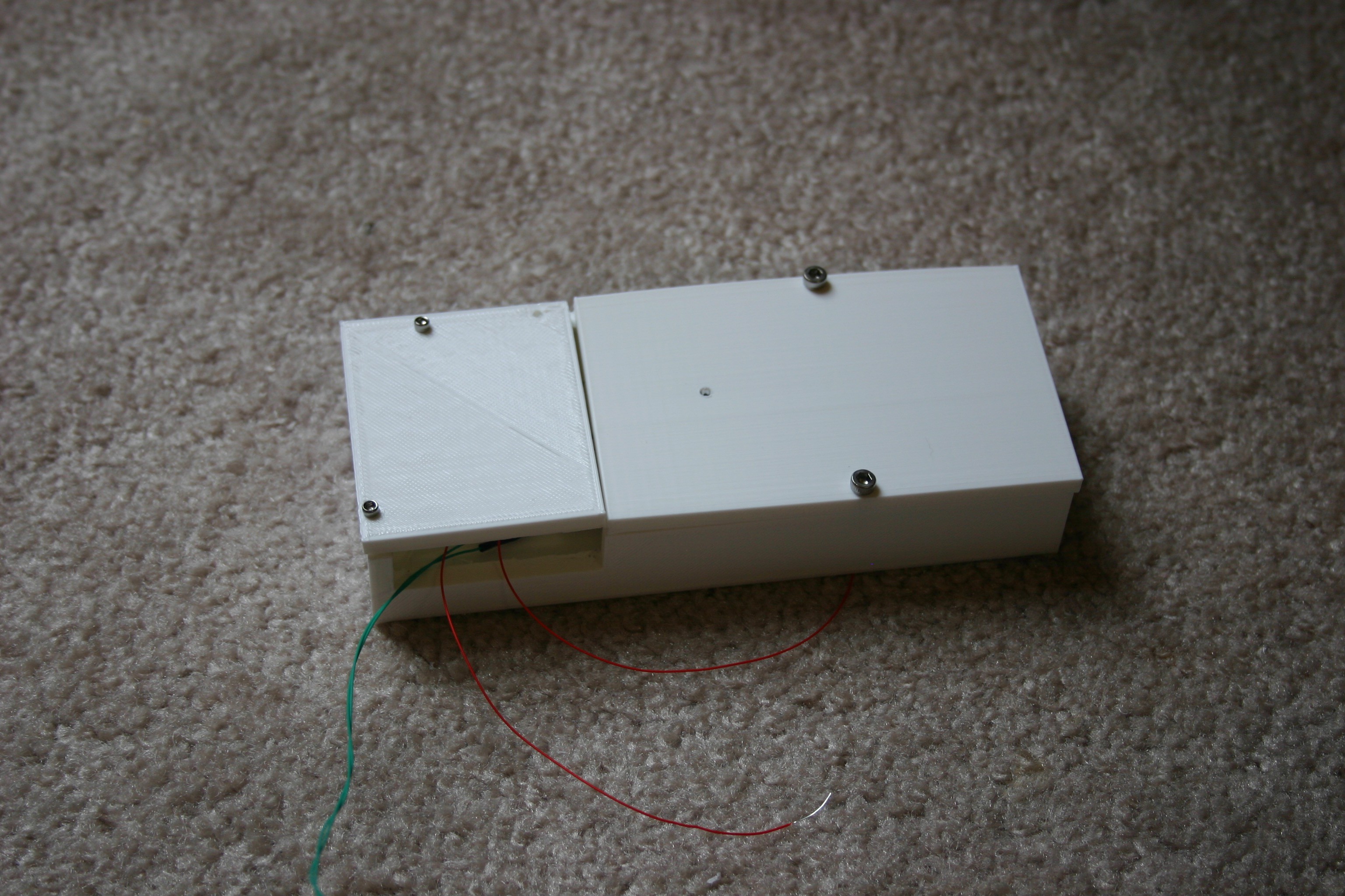
Assembled, they look like this.
![]()
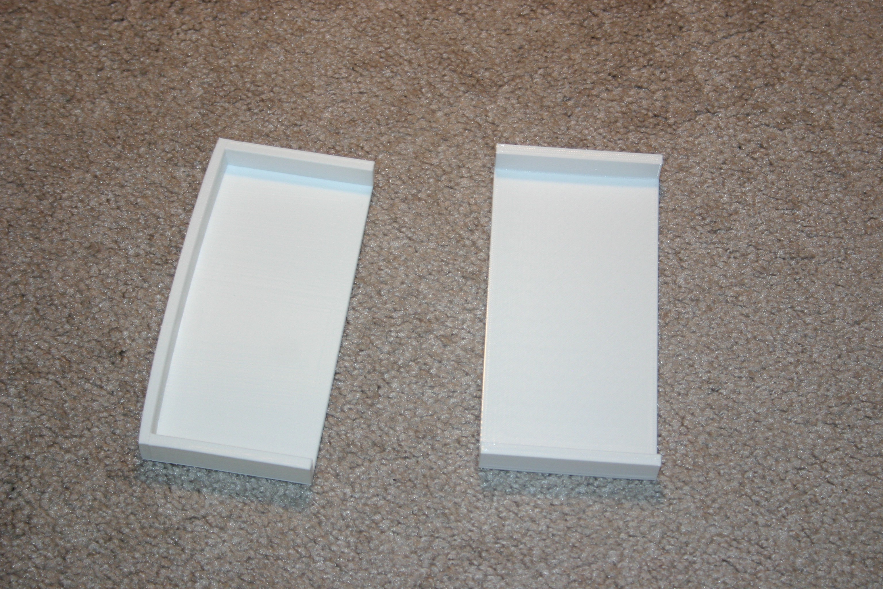
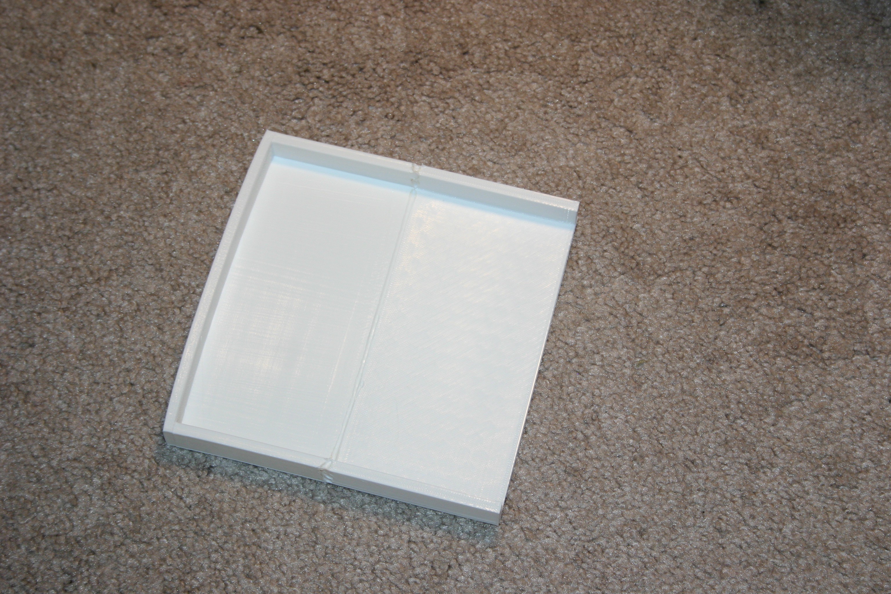
The "behind the book" housing is made from two pieces that are glued or melted together.
![]()
![]()
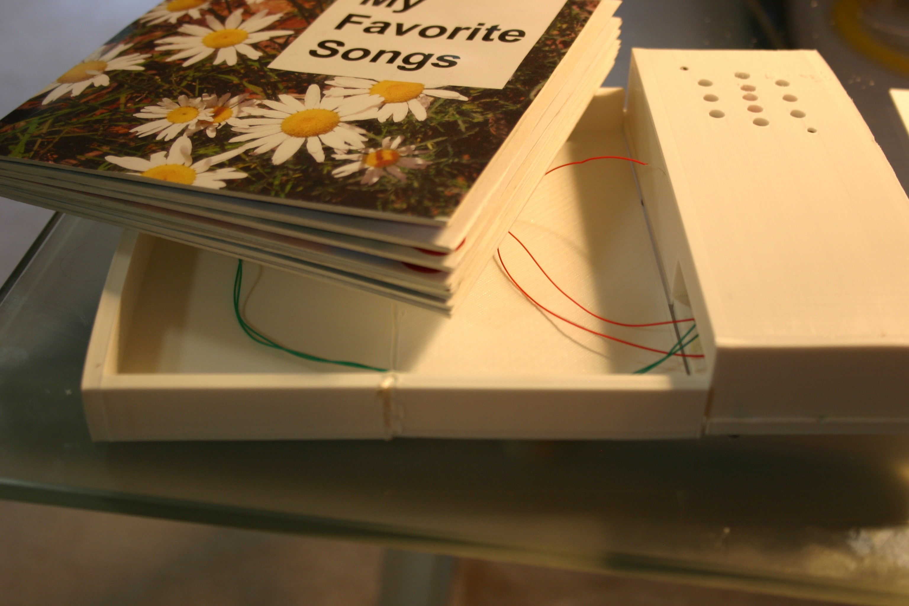
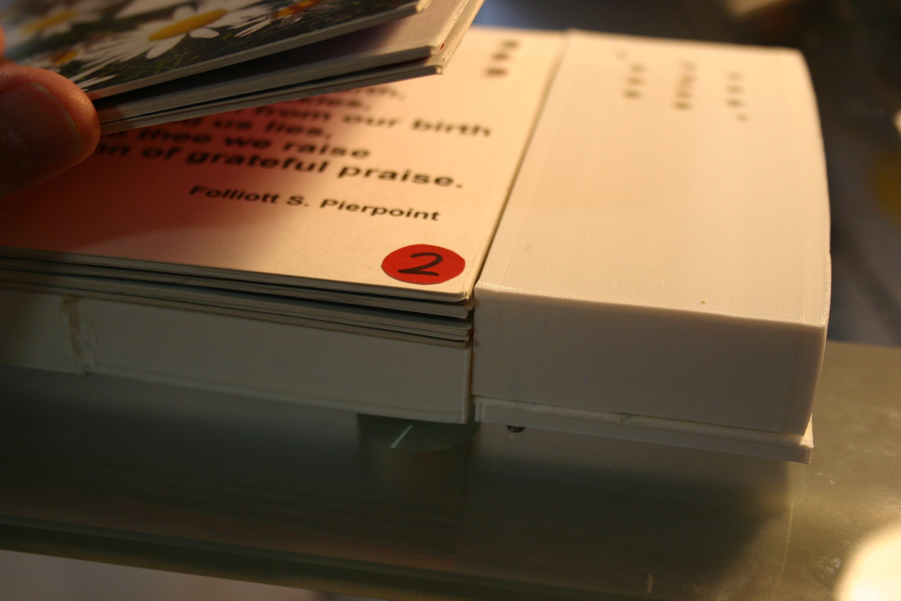
Now, the speaker assembly, electronics holder and book are coming together.
![]()
The speaker enclosure sits too high and prohibits easy access to the lower pages. The electronics housing will need to be raised to correct this.
![]()
-
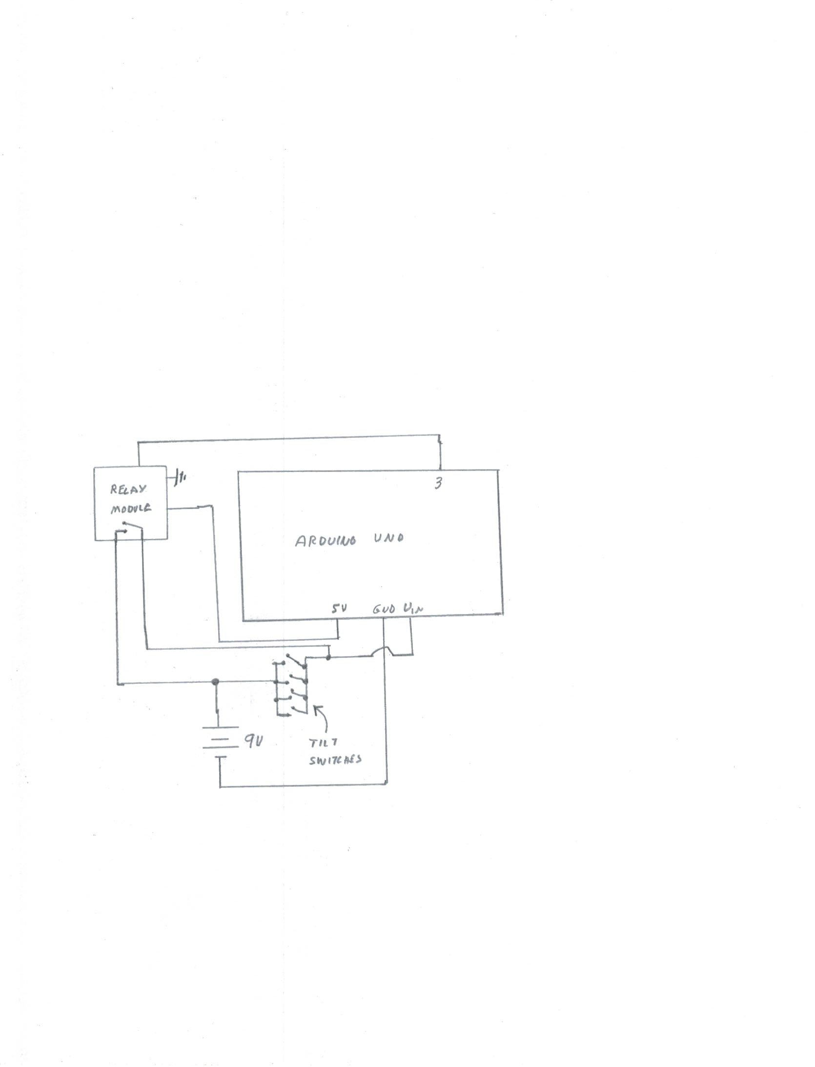
Power Lock On
07/31/2018 at 13:03 • 0 commentsAlthough the tilt switches can be used to indicate that the book has been picked up or set down, intermediate "holding the book flat" can result in power loss. By placing a relay contact parallel with the tilt contacts, the Arduino can hold power on for a couple of minutes (or until finished playing a song).
![]()
-
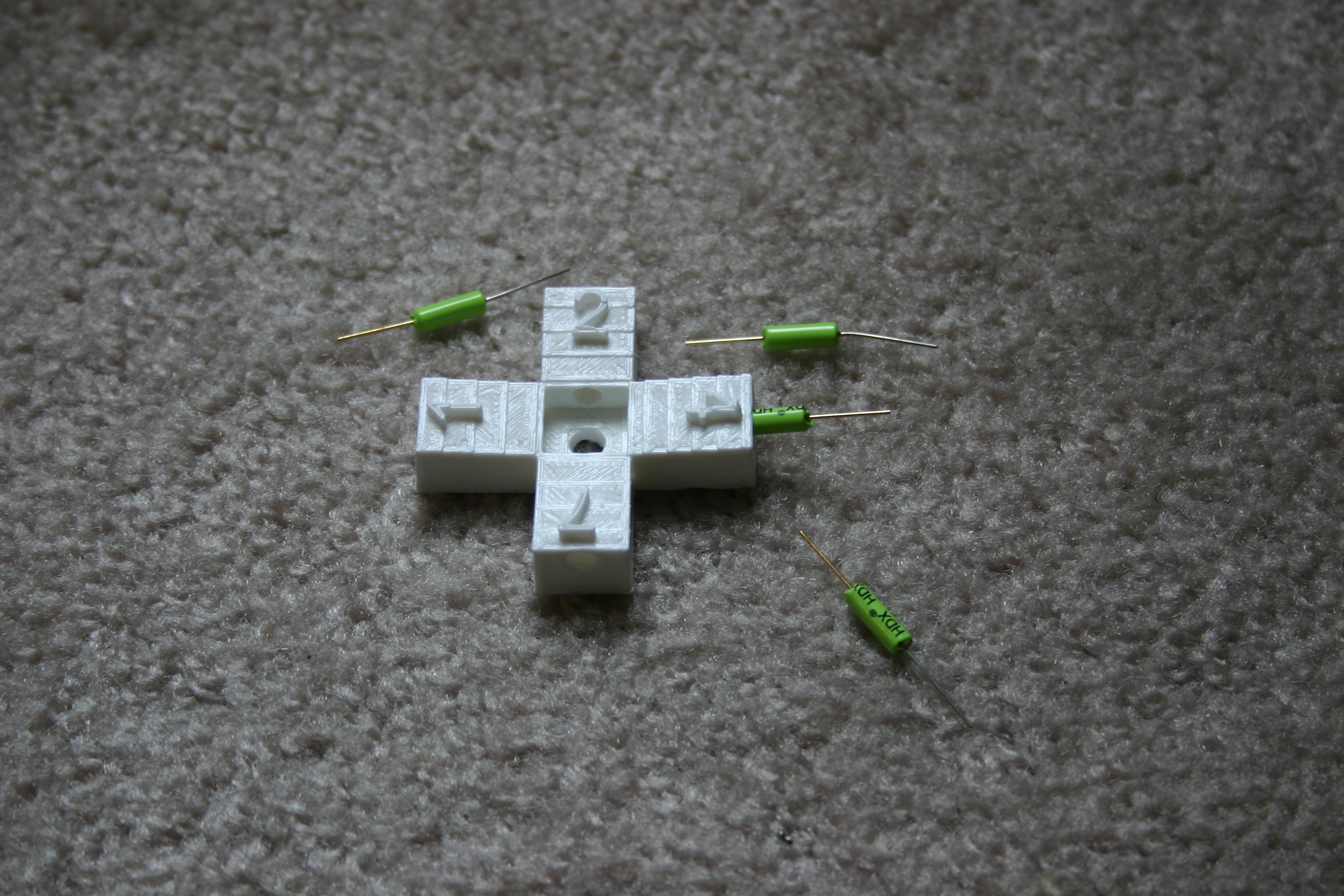
Pick Up the Book Detection
07/27/2018 at 13:42 • 0 commentsFour roller ball switches and a 3d printed housing (file available here) can be used to "know" that the book has been picked up.
The housing provides a slight downward tilt so that the roller ball switches are all reset when the book is resting on a flat surface. The short wire (brass color) should face outward--when the switch is tilted toward the brass wire end, electrical connection is made.
![]()
I use wire wrap wire to connect switches together. The four switches are wired in parallel.
-
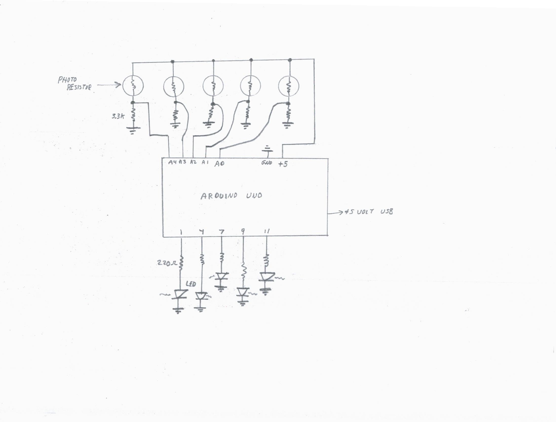
Page Selection
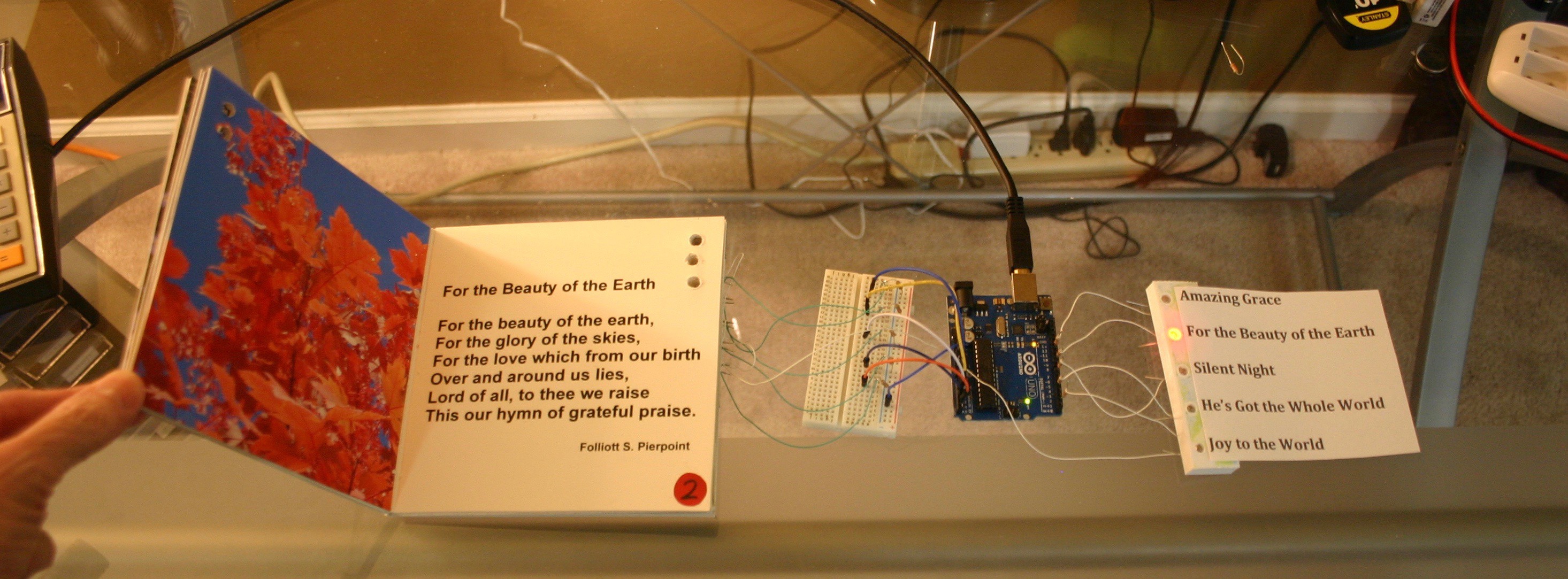
07/26/2018 at 18:09 • 0 commentsAutomatic page selection (our target audience may not be able to operate buttons and switches) is accomplished by reading the resistance of photoresistors.
![]()
At this stage, the output goes to light emitting diodes. In the final version, songs will be played.
Holes are drilled in the board book and corresponding photo resistors are lined up in the back of the book.
![]()
When light strikes a photo resistor, the Arduino "knows" that page is active.
![]()
The "deepest page in" is the one that should be activated.
![]()
The electronics have to be minimized in size and tied to the music playback system. The "Turn it on when picked up" system also has to be installed.
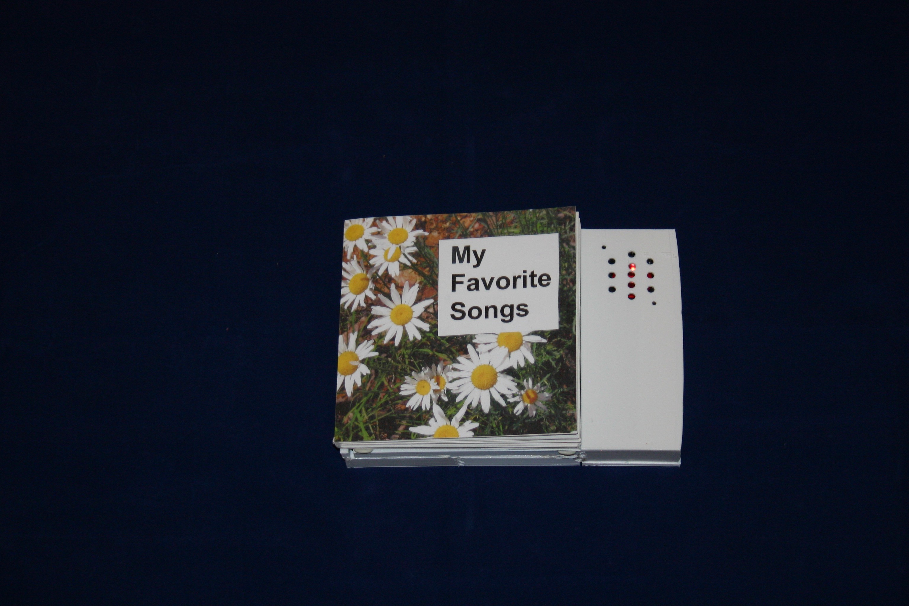
Notable Board Books
How alert and happy my mother (with Alzheimer's) became when she heard familiar songs! Lift the book, turn the page--the book does the rest.