Close
0%
0%

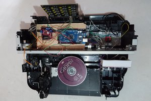
Coil Gun/Gaus Cannon

A device that uses electricity to propel a projectile at a significant speed.

Similar projects worth following
A semi powerful coilgun with current max velocities of about 150 FPS and about 30 joules of projectile energy. This equates to a 2% efficiency.

Coil Specs:  14g wire.  First Coil: 32 turns, 3 Layers  Second Coil 42 turns, 2Layers

Capacitors: 450v 10500 microFarad x 2

Firing Circuit:  Arduino Controlled SCRs

SCRs:  5x in parallel eupec tt66 SCR for 6750A peak @ 10ms  and 1 eupec tt500 SCR with 14.5KA peak @ 10ms

Gates: IR LEDs, and Photo Diodes.

Barrel: .5: ID .625" OD poly-carbonate tube

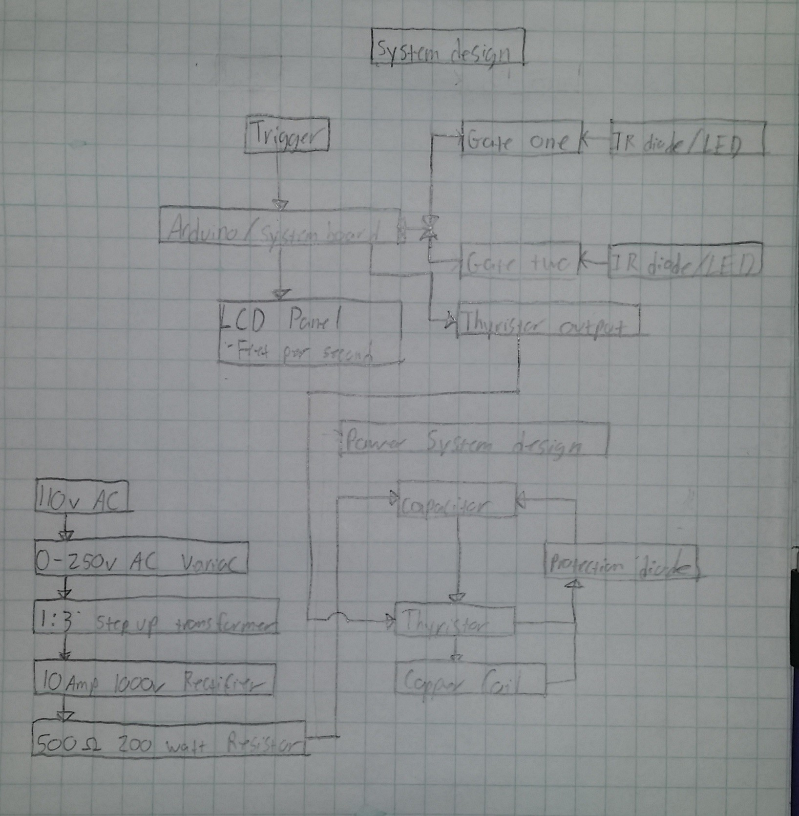
Charging Circuit:  Variac-step up transformer-full wave bridge rectifier-2x 1000 ohm 500 watt resistors in parallel-capacitors,  Caps are wired in parallel with a diode in between the positives of each to allow charging of both at the same time but the discharging of each at separate times.

The peak output per coil is close to 4000 amps @ 450v.

Current projectile speeds are approaching 300fps with projectile kinetic energy around 60 ft-lbs.

The Arduino mess is a work in progress it does a few things for me: 1. Fires the Coilgun (first coil, and also does the timing for the second coil) 2. Projectile Speed in FPS.

Projectile speed measurements are taken via 2 gates of photo diodes.

System Design:
  • CRT TV Destruction!

    jeff.ballard.8606/17/2014 at 23:41 0 comments

    As promised here is the destruction of a 27" CRT TV.  Each shot is at about 130 feet per second.

    I hope you enjoy!

    -Jeff

  • Updates! Circuit boards! Mistakes! Upcoming Plans!

    jeff.ballard.8606/17/2014 at 18:06 0 comments

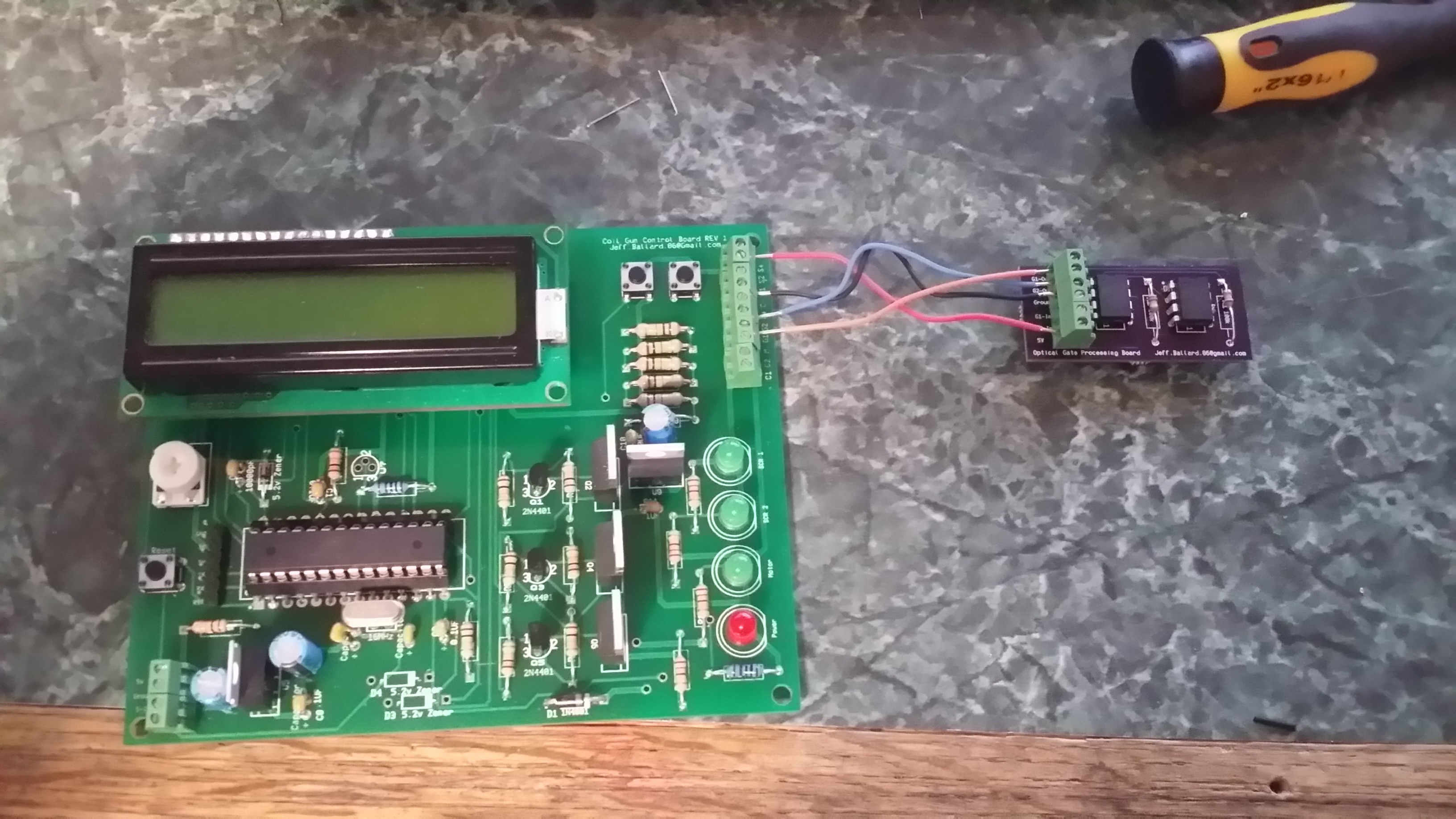
    I ended up using 2 boards, because I ended up making changes to the optical gate circuits after I had sent off for the main board.  Good news is that it was easy to just make a slave board for that portion of the circuit.

    I made a few mistakes when making the main board:

    1.  The three mosfets in a row needed a 10k resistor between pins 1 and 3.  I fixed this buy just soldering directly to the pins from under the board.

    2.  The blue cap in the middle right, the net wasnt connected for the positive lead.  Luckily it was close by, so I just bent the lead over and soldered it to the appropriate place.

    3.  The Atmega168 foot print was way messed up, it was almost double the width as it should have been.  I was able to fix it by using a large dip socket (with the center cut out) and manipulating the leads into the proper orientation.

    All of these mistakes could have been caught if I had only just printed the board traces/footprints out and visually inspected it and placed certain parts on top of their foot prints.

    There may be other mistakes, im new to designing my own boards, but this one functions as intended (so far.)  I also need to order a variety of connectors because what im using is just a PIA.

    Upcoming maybe today, at least within the next week:

    A friend donated a 27" CRT TV for parts with the request that I destroy the tube is a spectacular manner.  So I figured, why not shoot it with the coil gun.  Once set up and filmed I will post here for your viewing pleasure.

    I plan on testing projectile speed with different voltages, Im thinking that as Ive increased amperage, ive exceeded the capabilities of my projectile to absorb the forces applied to it from the coil.  I can control the amperage (and hopefully magnetic field) by changing the voltage.

    At some point a test rig to test fire a 1" diameter slug, just for the hell of it.

    And as always, thanks for viewing, and let me know what you think.

    -Jeff

  • The Hack a Day Prize

    jeff.ballard.8606/06/2014 at 14:24 0 comments

    This will be a short post talking about the Hack a Day prize and how my project is part of that contest.

    It seams that the largest requirement for the prize is that the project is "connected" from what I have read, and heard one of the judges say this only means connected to something.

    Since that is the case my project "Coil Gun/Gauss Cannon" is connected to a microcontroller (arduino).  This microcontroller controls all functions of the gun, including: firing, timing, measurement of voltage, measurement of projectile velocity, and other features as they become necessary. 

    Another requirement is that the project is open.  I have and will continue to post files that can be used to recreate my results.

    Lastly the contestant needs to actually build something, this is probably the easiest part.  There are many pictures that I have already posted that show the build process of my project, and there will be plenty more.

    Finally I'd like to wish everyone good luck, this is an excellent contest with extraordinary prizes. 

  • Ballistic Stabilization Update

    jeff.ballard.8606/04/2014 at 02:14 1 comment

    This will be a short update.  EDIT:  maybe not.

    Recently while awaiting funds to buy another SCR and some 10 or 8 gauge magnet wire, I have been experimenting with Ballistic Stabilization.

    If you read a few logs ago you may have seen that I purchased a 1/2" diameter 5v dc motor that unloaded can spin up to 12k RPM.  I also 3D printed a motor mount and a magnet holder for the motor.  When I installed this into the poly carbonate tubing without the coil it would spin perfectly.  What im about to say should have been obvious to me, but didnt occur to me until I did it.  When the coil gun was fully assembled I decided to test out my "Ballistic Motor" I would spin it up and then push it forward until about 1/4" of the projectile was inside the coil.  That is when the projectile would slow to a stop and not move.  I dont perfectly know whats going on, but I am assuming it is along the same principle of an electric motor.  My assumption is that the coil and projectile are imparting a generator type effect.  And this is effectively making it really hard to spin my little motor up.

    So then I decided, ill use a more powerful motor.  I then disassembled an old RC helicopter, and repeated the experiment with one of its much stronger/faster motors.  Failure.  But this time I was able to take at least one interesting measurement from the motor.  At no load full RPM the motor pulled about .6A at 5v, at full load the motor would pull almost 6A at 5v, and become very hot very fast.

    So over the past couple days I have been thinking of going with an even larger brushless motors, I have a couple 156kv 2200kw motors I could use.  This comes with a couple problems: they would require much more voltage and they would also require a simi complicated mounting system.  Lastly I decided to do some research on firearm projectile RPMs. I am astonished to say that a projectile in a modern hunting rifle can see RPMs in excess of 200k.  Even for myself, a person highly knowledgeable with firearms I was really blown away.

    So then I thought can I spin a 1/2" diameter steel rod even 100k?  And I thought sure, I can get a high KV motor, give it lots of voltage, and some gears and I could spin it however fast I wanted to.  I didnt think this for long, because I believe that its too complicated, it may not look it but I do believe in the K.I.S.S. principle.

    Im thinking I may experiment with some different projectile shapes and try to accomplish some sort of ballistic stabilization in some other manner, it may be revolutionary, it may be barbaric, who knows. 

    For those of you who may have skipped down here:

     "To keep a long story short" Spinning a projectile while it is partially in a coil is not an easy feat, and has almost been given up on in its current form.

    And again, thanks for visiting, reading, comenting, and whatever else you may do.

  • New Video!

    jeff.ballard.8605/28/2014 at 21:20 0 comments

    New video is a little blurry/short, I won a rebel T3I and well im used to camera phones so, maybe the next one will be better.

    I finaly got the Optical gates working, and oscilloscope would have helped greatly :(  I finally was able to get it working with some crude spice models + trial and error.  I will post schematics at a later time.

    In the video the projectile went clear through the plywood, the plywood is 3/8" thick, it also left a good sized ding on the wall behind it.

    Projectile speed was measured at less than 150 fps which leads me to believe my 300 fps results from the previous gun was kind of fishy, especially since you can see the projectile moving in the above video.

    this shot was at 400v, 10500uF x2 or about 1850 joules of stored energy, projectile energy was just over 30, which is close to a 2% efficiency.  I may play with it and try to get more outr of it, but i want to up the Amperage again.  Im thinking 10KA per coil with adjustable timers again.

    I also tested the coil gun with one coil and then 2 coils to see what the differences would be:

    I decided to use 400v instead of 450v as the voltage.  I used the same projectile.  An lastly I made sure that the projectile was on the same spot with each shot.  One coil averaged 70 fps while 2 coils averaged 130 fps.  Close to a 45% improvement.

    Please comment and let me know what you think, or advice is always welcomed!

    -Jeff

  • New Schematic and Board Layout

    jeff.ballard.8605/21/2014 at 17:39 1 comment

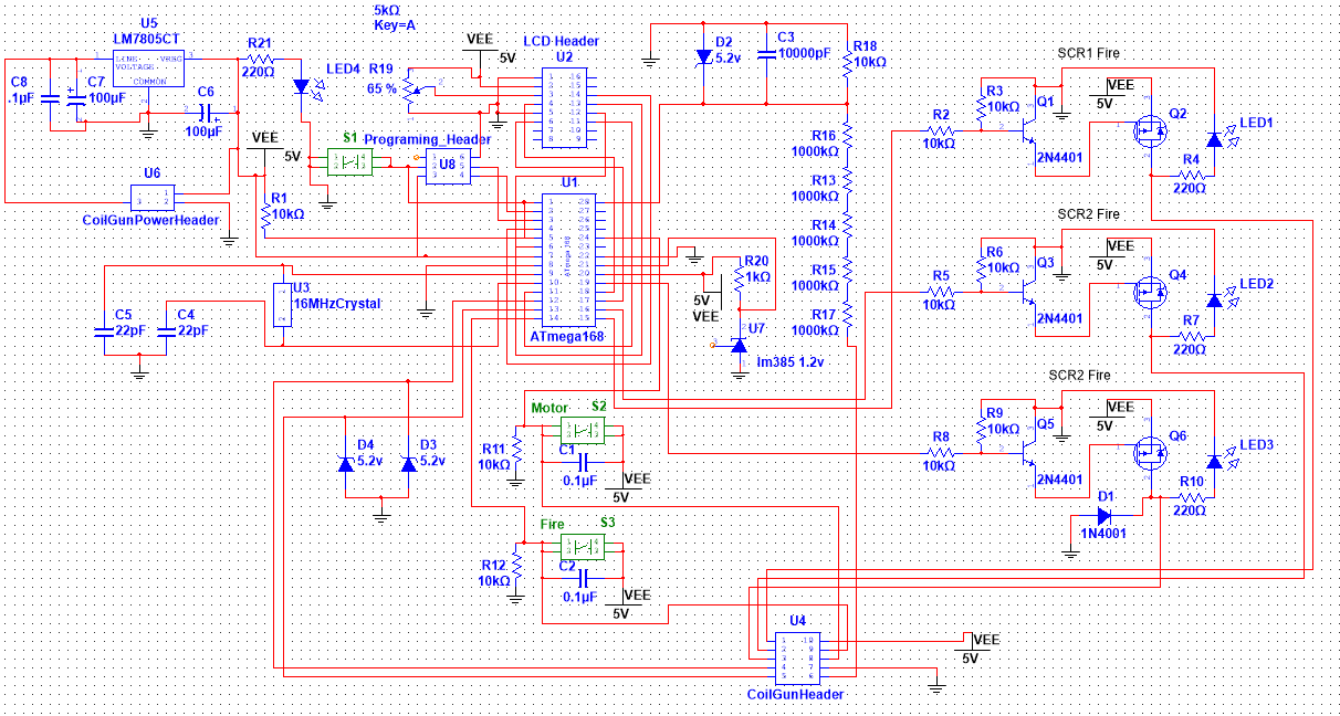
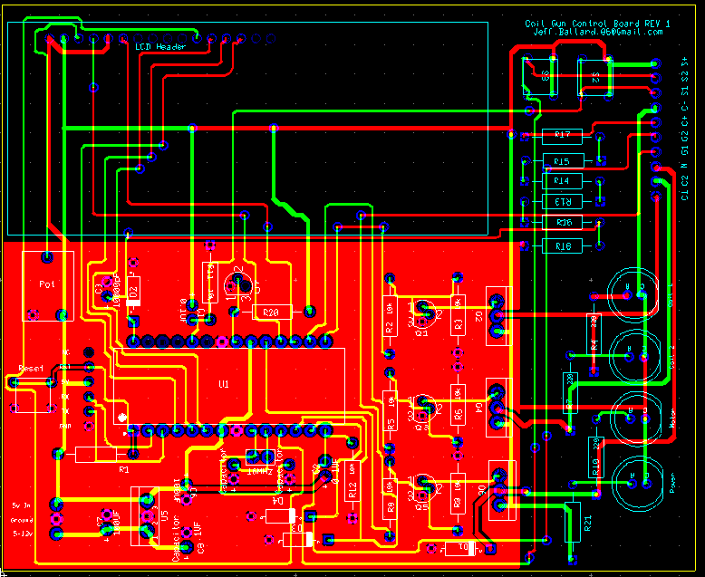
    Recently I have not had a lot of time to work on this project, but I have had time to finally record the actual circuit diagram and create a PCB.  I will send off to have the PCB made in a few weeks.  Warning: my schematic and PCB fab skills are not very good, proceed with caution.  For many of the components I just made basic place holders for them, hopefully it can be followed.  I also used an autorouter for about 90% of my traces.

    Also the 2nd title that says SCR2 fire is actualy Ballistic Motor.

    I should also add that im debating on going back to a single coil design pushing 14KA through its single coil.

  • Ballistic Stabilization

    jeff.ballard.8605/06/2014 at 20:53 5 comments

    So I trimmed out my back door today, and then decided to make something for my coil gun.

    I purchased some .5 id .625 od poly-carbonate tubing a while back, along with a little 6v motor.  So I 3d printed a motor mount and a magnet mount (attaches a magnet to the end of the motor shaft.)

    The motor mount has a hole that I will thread with a 8-32 tap and it will except a threaded rod to be used as repositional stop so I can test projectile placement in relation to the coil.

    The projectile will attach to the magnet, the motor/projectile assembly will then slide into the barrel, motor will spin up, coil gun will fire, and hopefully will have a stable ballistic path.

    I also printed out some new coil endcaps that will also be used as my new photo gates.  I expect to push nearly 4000 amps through each of the new coils, I am also hoping to reach projectile speeds in excess of 500 feet per second.

  • Coil Schematic

    jeff.ballard.8605/01/2014 at 04:53 5 comments

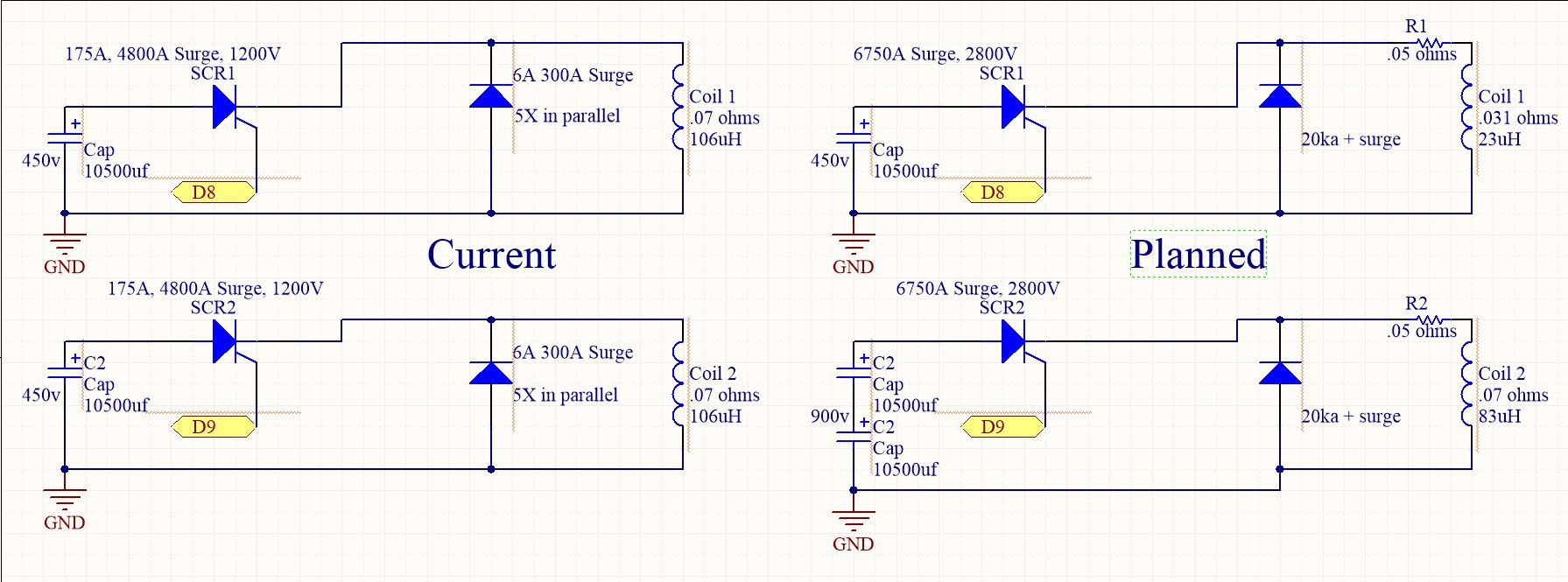
    As requested here is the coil schematic.  The left side is current, the right side is planned for the future.


    left side produces about 2800A per coil, Right side will produce approximately 4000A per coil, with one at 450v the other at 900v.

  • Explosion! Updated

    jeff.ballard.8604/30/2014 at 19:10 1 comment

    Today I switched out the photo transistors with photo diodes.

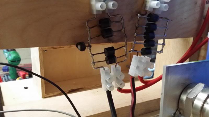
    I then started testing.  started at 100v, 150v, 200v...so on until i was up to 445v.  On this test, I had a protection diode explode! My coil protection consists of 5 6A diodes with a 300A peak wired in parallel with the coil.  

    Sadly along with the loss of a single diode, I also must have blown some pins on my arduino,  and/or the LCD.  The arduino still seams to respond to some of my inputs.

    an hour later and my ears are still ringing, and im still expecting the police to show up asking about the noise...

    UPDATE:

    I went out to my garage to play with it a little, and what has happened is my second SCR has failed.  I was aware that this SCR wasnt completely right because it took an extraordinary amount of current to make it conduct, compaired to the other SCR.

    Also the Arduino and LCD screen are fine, after the min explosion, it didnt seam to be working correctly, so I just powered everything down, a power reset was all that was needed it would seem. 

    So I am now working with a single coil again, I will start to look for another SCR, and continue testing with the electronics.

    UPDATE 2:

    I ordered 2 power diode modules, PN LS412460 they have a 20kA+ surge capability, I will use these as my new SCR protection devices.

    I also ordered 5 SCR modules, each SCR module has tow SCRs wired in series, I'll wire all three terminals in parallel and use one of each banks for each coil.

  • Current Code

    jeff.ballard.8604/29/2014 at 16:33 0 comments

    Now if you are looking at this remember I am a code noob, constructive criticism is highly encouraged.

    Code:

    #include <LiquidCrystal.h>

    #include <EEPROM.h>

    //variables

    LiquidCrystal lcd(12, 11, 5, 4, 3, 2);

    float time = 0;

    unsigned long StartTime = 0;

    unsigned long StopTime = 0;

    float timer;

    float gateD = 3.6; //distance between gates in inches

    float gate = 0;

    float fps = 0;

    float seconds = 0;

    int FireDelay; //second SCR fire Delay

    int FireDelaySave = 0;

    float Debounce = 50; //button debounce time

    //pin states

    int UpButtonState;

    int DownButtonState;

    int FireState;

    int SaveButtonState;

    int FireButtonState;

    //pin labeling

    const int Up = 30;

    const int Down = 32;

    const int Save = 36;

    const int FireOne = 9;

    const int FireTwo = 8;

    const int FireButton = 31;

    const int SecondCoilGate = 38;

    const int SpeedTrapOne = 48;

    const int SpeedTrapTwo = 50;

    //EEPROM saving variables

    int FireDelayAddress = 1;

    int FireDelayMultiplierAddress = 2;

    int FireDelayMultiplier;

    void setup()

    {

    Serial.begin(9600);

    lcd.begin(16, 2);

    pinMode(FireTwo, OUTPUT); //Second SCR fire mosfet

    pinMode(FireOne, OUTPUT); //First SCR fire mosfet

    //digitalWrite(FireOne, HIGH);

    //digitalWrite(FireTwo, LOW);

    FireDelay = EEPROM.read(FireDelayAddress); //read FireDelay from eeprom

    FireDelayMultiplier = EEPROM.read(FireDelayMultiplierAddress); //read multiplier from eeprom

    if (FireDelayMultiplier != 1 | FireDelayMultiplier != 2 | FireDelayMultiplier != 3){ //1st boot up sequence if mulitiplier is not equal to 1,2, or 3, set to 1 and set default fire delay

    FireDelayMultiplier = 1;

    FireDelay = 500;}

    if (FireDelayMultiplier == 1){

    FireDelay = FireDelay;}

    if (FireDelayMultiplier == 2){

    FireDelay = FireDelay * 10;}

    if (FireDelayMultiplier == 3){

    FireDelay = ((FireDelay * 2)*10);}

    }

    void loop()

    {

    digitalWrite(FireOne, LOW);

    digitalWrite(FireTwo, LOW);

    if (digitalRead(Up) != UpButtonState) //Up Button Code

    {

    UpButtonState = digitalRead(Up);

    if (UpButtonState == HIGH)

    {

    FireDelay = FireDelay + 20;

    lcd.clear();

    lcd.setCursor(0,1);

    lcd.print("Fire Delay");

    lcd.setCursor(11,1);

    lcd.print(FireDelay);

    lcd.setCursor(14,1);

    lcd.print("uS");

    delay(Debounce);

    }

    }

    if (digitalRead(Down) != DownButtonState) //Down Button Code

    {

    DownButtonState = digitalRead(Down);

    if (DownButtonState == HIGH)

    {

    FireDelay = FireDelay - 20;

    if (FireDelay < 0) {

    FireDelay = 0;

    }

    lcd.clear();

    lcd.setCursor(0,1);

    lcd.print("Fire Delay");

    lcd.setCursor(11,1);

    lcd.print(FireDelay);

    lcd.setCursor(14,1);

    lcd.print("uS");

    delay(Debounce);

    }

    }

    if (digitalRead(Save) != SaveButtonState) //save Button Code

    {

    SaveButtonState = digitalRead(Save);

    if (SaveButtonState == HIGH)

    {

    if (FireDelay < 260) {

    FireDelayMultiplier = 1;

    FireDelaySave = FireDelay;

    }

    if (FireDelay <= 2500 && FireDelay >= 260) {

    FireDelayMultiplier = 2;

    FireDelaySave = FireDelay / 10;

    }

    if (FireDelay <= 5000 && FireDelay > 2500) {

    FireDelayMultiplier = 3;

    FireDelaySave = ((FireDelay/10)/2);

    }

    EEPROM.write(FireDelayAddress, FireDelaySave);

    EEPROM.write(FireDelayMultiplierAddress, FireDelayMultiplier);

    delay(100);

    lcd.clear();

    lcd.setCursor(0,1);

    lcd.print("Saved");

    delay(1500);

    lcd.clear();

    lcd.setCursor(0,1);

    lcd.print("Fire Delay");

    lcd.setCursor(11,1);

    lcd.print(FireDelay);

    lcd.setCursor(14,1);

    lcd.print("uS");

    }

    }

    if (digitalRead(FireButton) != FireButtonState) //Fire Sequence

    {

    FireButtonState = digitalRead(FireButton);

    if (FireButtonState == HIGH)

    {

    //delay(Debounce);

    digitalWrite(FireOne, HIGH); //fire first SCR

    while (digitalRead(SecondCoilGate) == LOW) {

    } //wait until projectile trips gate

    StartTime = micros(); //FPS measurment start

    digitalWrite(FireOne, LOW); //turn first SCR off

    delayMicroseconds(FireDelay); //delay until projectile is in the perfect spot

    digitalWrite(FireTwo, HIGH); //Fire Second SCR

    delay(1); //delay to give secoond scr to start up

    digitalWrite(FireTwo, LOW); //turn second SCR off

    while(digitalRead(SpeedTrapTwo) == LOW) {

    } //First sensor was tripped, now wait for second sensor to trip

    StopTime = micros(); //second part of FPS measurment

    time = StopTime - StartTime; //time...

    Read more »

View all 11 project logs

Enjoy this project?

Share

Discussions

APBurner wrote 08/05/2014 at 01:57 point
I built one of these thing with multi-coil in the early 80's. It was purely mechanical control. I hooked the coils to 6 lead acid gelcells in series through a 10 position rotary switch. and just turned the switch at an accelerating rate. once I got the projectile to go about 100ft. The projectile was a 10 penny nail with the head cut off and the tube was and old car antenna which was brass coated with chrome. It was fun.

  Are you sure? yes | no

J Groff wrote 07/11/2014 at 19:39 point
Your spin up idea is on the right track. All these designs fart a round into the chamber cold with no KE and they leave without spin stabilization. Read this:http://www.infolytica.com/en/applications/ex0176/halbachmagnetizationcasestudy.pdf
Create a halbach cylinder by using a delryn nylon cylinder with a hole in the center, you can get them at hardware store in various sizes. I used 15mm. Surround the outside with 3 or 5mm rare earth magnets in the halbach pattern and use large heat shrink tubing to hold them all in place. FInd a rod that fits the center of the delryn cylinder, stainless steel. Construct the stator to go outside the barrel at the breech. Your ammo is the rotor. Apply rotating field to the round in the chamber and you have spin stabilization. You'll have to figure out how to hold the rod while ammo is loaded and spun up. I'm not going to reveal that part as its in my patent application ;] Sorry I cant condone or take responsibility if you build this so be careful as rare earth magnets have the interesting property of secondary detonation on impact and can be toxic.

  Are you sure? yes | no

Nippey wrote 07/04/2014 at 06:19 point
This project damn cool. ;)
I tried this long time ago. After finishing university, I understand why it didn't work at so many points. I should give it another try.

Btw: I am quite unexperienced with non-metric numbers.. Do you mind to add some numbers with m/s? :)

  Are you sure? yes | no

jeff.ballard.86 wrote 07/04/2014 at 12:31 point
I will do my best to include dual units for future updates.

Great request! Thanks

  Are you sure? yes | no

Steve Shaffer wrote 07/11/2014 at 12:33 point
As an American engineer who is good at both metric and non-metric, you should take the time to learn both.

  Are you sure? yes | no

Nippey wrote 07/11/2014 at 15:44 point
Hey Steve, I feel addressed (I guess I'm the one you mean) ;) by your comment!

You're right, in my job I am confronted with different units several times a month. So I should know the relations. But let's call it lazy. I like convert them with tools, when creating a new text.

But, I see your comment as motivation to learn them by heart! Even if I'm a European engineer ^^

  Are you sure? yes | no

Philip Ian Haasnoot wrote 06/25/2014 at 01:55 point
Nice work so far, Coilguns are very dear to my heart. The few I've built were single stage running off of a DC power source & boost converter. Looking forward to more updates, just be safe!

  Are you sure? yes | no

Sagar wrote 06/17/2014 at 18:08 point
what if you used air pressure, along with the coils to boost the power. Some sort of Hybrid cannon?

  Are you sure? yes | no

jeff.ballard.86 wrote 06/17/2014 at 18:35 point
I did briefly think of this, and I believe it would make an incredible build. The only reason I haven't gone that route, is because of my goals for the project, im trying to make an exclusive coil gun. In the future I may experiment with the use of air pressure or with vacuum.

  Are you sure? yes | no

Mike Szczys wrote 06/05/2014 at 15:51 point
Thanks for entering this one in The Hackaday Prize. Check out the basic judging criteria on this page: http://hackaday.io/prize/details

Have you thought about what makes this device "connected"? You should probably add a section talking about this so the Judges will have an easier time learning about that aspect.

Cool build!

  Are you sure? yes | no

zakqwy wrote 05/01/2014 at 04:09 point
If you haven't already, it's worth reading through some of Sam Barros' writeups on his Powerlabs site. He's been developing a few garage railguns for some time now, might give you some good tips on HV energy storage stuff. Also (obviously) be careful!

  Are you sure? yes | no

zakqwy wrote 05/02/2014 at 14:02 point
Another honorable mention is Gordon McComb. If you haven't checked out his books, they're worth a look; the Gadgeteers Goldmine and Lasers, Ray Guns and Light Cannons both deal with HV energy storage stuff (mostly for pulsed laser projects). Again: be careful, those caps can kill.

  Are you sure? yes | no

jeff.ballard.86 wrote 05/02/2014 at 14:41 point
ive read alot of Sam Barrows stuff. I will have to check out the books as well. And your right these caps have more than enough energy to kill, I do my best to keep myself safe.

  Are you sure? yes | no

dave.m.mcdonough wrote 05/02/2014 at 23:33 point
good find.
http://www.powerlabs.org/multistagecg.htm

Looks like he had a similar issue when attempting a dry fire. I think I will be running a lot of simulations and careful clamp design when I reach this stage.. I would like to be able to dry-fire this thing without fear of it exploding. I might come up with something soon since I happen to be thinking about it.
I've used a clamp design in the past where the energy was sent into a cap with power resistors across it. RC snubbers help too but I think this spike is too potent for that, need to steer that bulk amount of energy from the inductor to somewhere safe. Ideally back into the main charge caps!

  Are you sure? yes | no

jeff.ballard.86 wrote 05/03/2014 at 01:10 point
Dave ive read about designs that have 2 banks of caps. When you fire the coil gun, the discharge does a partial charge for the next fire, allowing for faster charge times. it also boosts efficiency.

  Are you sure? yes | no

dave.m.mcdonough wrote 05/03/2014 at 15:38 point
That's an interesting thought. I wonder how much energy is pushed forward? Do you have any links? I need details! :)

  Are you sure? yes | no

dave.m.mcdonough wrote 05/03/2014 at 19:51 point
I think I answered my own question there.
http://hackaday.io/project/958/log/2280

  Are you sure? yes | no

Eric Evenchick wrote 04/30/2014 at 04:48 point
You mention a 4% efficiency, but for someone with no frame of reference how good or bad is that for a coil gun?

  Are you sure? yes | no

jeff.ballard.86 wrote 04/30/2014 at 14:28 point
Most coil guns are below that amount. I was actually quite surprised when I calculated that. I also know of a couple areas where this one is terribly inefficient, allowing for possible gains.

The first area is in the second stage timing. I dont believe that the combination of a photo transistor and measuring the second firing delay in milliseconds, is allowing for accurate stage firing. I believe that it is actually firing after the projectile leaves that coil, possible trying to pull the projectile back in a little bit. I know this because the coil gun was shooting just as fast with one coil, which would mean that with one coil I had an 8% efficiency.

Second is adding some iron around the coils.

Third is a laminated projectile.

Thanks for your comment.

  Are you sure? yes | no

dave.m.mcdonough wrote 04/30/2014 at 14:48 point
I'm figuring on 6% efficiency for the calculations on mine, based purely on speculation and other people's results. And that I will have a core around the coil. Open air core not as efficient.

  Are you sure? yes | no

jeff.ballard.86 wrote 04/30/2014 at 15:09 point
do you plan on using a laminated core or just Cast Iron, or even steel?

Im hoping to find a piece of scrap cast iron pipe, cut it into thin sections and put a fine weld along it like in transformer cores to hold it together. I plan the same for a future projectile, except laminated steel.

  Are you sure? yes | no

dave.m.mcdonough wrote 04/30/2014 at 15:59 point
I'm considering doing a pressed powered iron type thing. The first (slowest) stage will see a 1ms pulse, but it quickly drops. The last few stages are closer to 100us.. Speaking in frequency we are starting at 500hz and ending at almost 5khz. Not quite high enough to justify mumetals or ferrite for material. And if I put a bolt or something heavy for ammo then things will slow down quite a bit.
The powered iron approach will let me make a custom shape which will be physically convenient for stacking a bunch of stages next to eachother but eddy current losses will be in full effect. Doing laminated sections seems like it would be obnoxious but should be more efficient. I would not weld them though, that creates a conductive path which will undo the lamination efforts. Maybe cut them so they sandwich nicely between the barrel and a larger diameter PVC pipe? I've decided not to be too concerned with eddy loss because it's not going steady like a transformer, they are pulses. And as far as the projectile itself goes I don't see how it will matter. Maybe if it's long enough? If you try it then take careful readings, I'm curious. I'll be trying a few variations of coil and core later on after the power supplies are done but that is several months away.

  Are you sure? yes | no

jeff.ballard.86 wrote 04/29/2014 at 22:57 point
I charge the caps to 435-445v
i have 5 6A, 300A surge diodes wired ip in parallel with each coil.
A scope would be extremely useful, but at this time I do not have one, its on my to buy list.

Im thinking of adding maybe one more coil or putting my SCRs in parallel and using some 8-10 guage wire for a massive single stage. If I do this I plan on 8k-9k amp surge.

  Are you sure? yes | no

dave.m.mcdonough wrote 04/29/2014 at 19:16 point
Good start. You're a lot farther along than I am. :)
What voltage are you charging the caps to?
I am intending to just buy a chrono off an airsoft site and use that to measure output speed and get the delays dailed in. I'm also intending to use optical triggers for each coil.
Are you using freewheel diodes on the coils or any voltage supression? Do you have a scope or any way to watch what the voltage is doing?

  Are you sure? yes | no

Similar Projects

Does this project spark your interest?

Become a member to follow this project and never miss any updates