-
Laser diode thermal management
07/20/2016 at 17:13 • 0 commentsI'm looking at one version of the laser diode housing that will use 3D printed sintered aluminium, with the minimum of material to reduce costs.
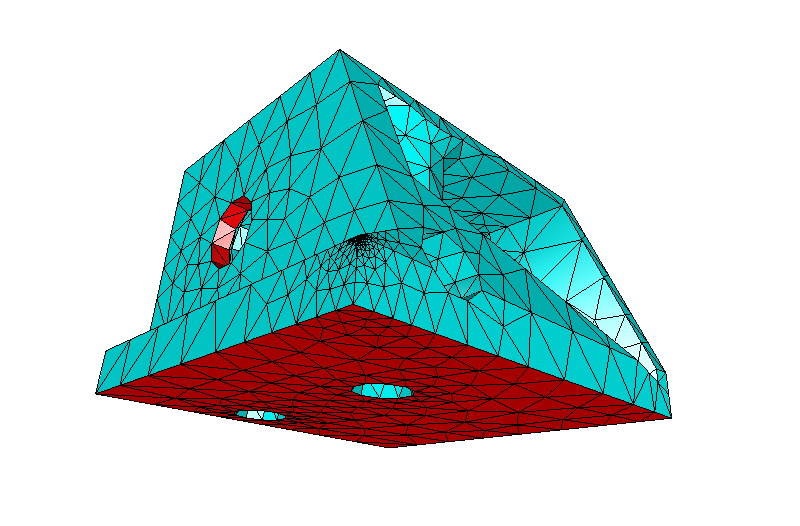
The following design is a first pass that should have sufficient material for both supporting the focus tube, fixing bolts, thermocouple recess and providing sufficient thermal coupling for the diode.
Researching open source thermal FEA packages as an alternative to the commercial packages, lead me to ELMER which is a multi-physics solver capable of solving all sorts of problems.
The diode block was imported and the temperature of the TEC face defined as a heat boundary condition of 25'C and the diode interface ring defined as heat boundary condition with a heat flux of 2.1W over the area of the selected faces.
![]()
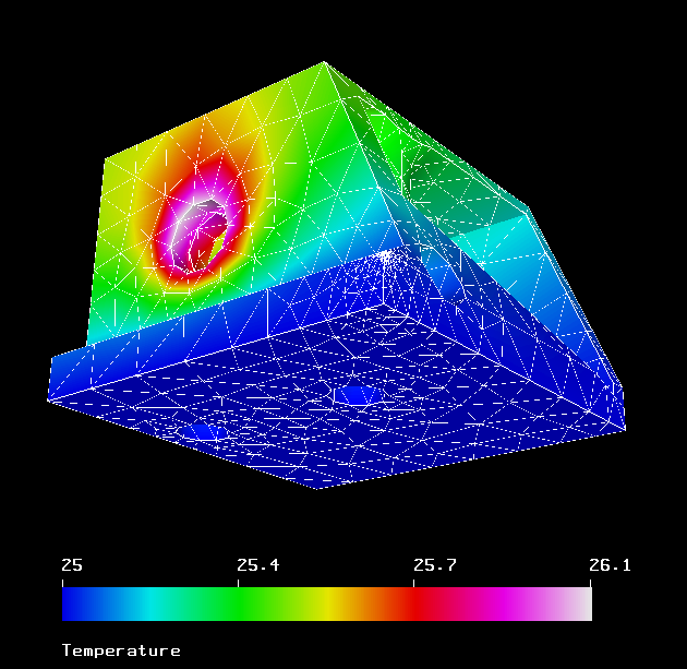
Running through gave the following results, which show that the diode block provides sufficient material to dissapate the generated energy of the diode. And the diode temperature will be approxamtly one degree higher than the TEC set point.
![]()
The following snippets for Elmer are firstly to scale the model from millimeters to meters
Coordinate Scaling = Real 0.001This section is setting the temperature of the face adjacent to the TEC to 25'C
Boundary Condition 1
  Target Boundaries(1) = 28
  Name = "TEC-temp"
  Temperature = 25
End
This section sets the diode interface heat flux (thermal load entering the system)
Boundary Condition 2 Target Boundaries(2) = 17 21 Name = "diode-heat" Heat Transfer Coefficient = 237 Heat Flux = 1.734e5 End -
Laser driver board testing
07/08/2016 at 14:36 • 0 commentsWell one milestone has been completed and that is getting the laser controller board tested. This covers the following;
- Setup control of the DAC to allow calibration of the control voltage to the iC-HKB laser control ICs. The coarse level current control is via a resistor, with fine control via the voltage (tuning).
- Setup of the FIFO through the Flexible Flat Cable (FFC) to allow loading of data from the arduino used in testing
- Setup of the ADC that, in conjunction with a current sensing resistor allows the control voltages to be calibrated against a laser diode test load (diodes and a thick film resistor)
- Overview of components tested;
- 9bit FIFO
- I2C x8 12bit DAC
- I2C 16bit ADC
- x8 iC-HKB laser diode controllers
A number of functions were needed to step through the process and allow confirmation of the data reported by the ADC. And then to speed up the read out clocking to test the behaviour at speed. I would like to test with the diode, but have yet to get the heat sink design finalised and fabricated. And without heat sinking it will burn out.
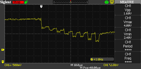
Low speed clock out, spikes are where the FIFO read signal is switched to clock the data out. The driver acts as a current sink, so the higher the current flow, the lower the voltage in the chart below.![]()
![]()
I ran each of the ICs individually to allow me to measure the voltage over the current sense resistor with the multimeter (resolution was ~0.2mA) which shows reasonable match in readings. Likely within the error range for both devices.
![]()
Plot below is speeding up the read out to the max achievable by the arduino through bit banging the read pin of the FIFO. My calculations indicate that a clock out speed of ~1.5MHz is required, this is the main reason that i'm using a hardware readout system to generate the the clock pulse train and to enable and disable it; the secondary red laser diode and a pair of photo diodes. The raspberry Pi will have 9ms to re-load the FIFO for the next line of data.
![]()
-
Electrical system components overview
07/04/2016 at 21:26 • 0 commentsThis shot shows the majority of what will be the prototype printers guts;
top-right - TEC controller with TEC and thermistor, moving left is the focus stepper with trigger laser below (lit up), and left again is the hexagon mirror motor.
bottom-right - printer head, consisting of the FIFO and UV laser board, Arduino, variable frequency generator, humidity and temp sensor, point of use DC-DC (12v to 5v for head). UV laser test load (diodes and resistor) attached for safety.
bottom-middle - Raspberry Pi Zero on 5v i/o breakout including full size USB-A socket. Connected to the print head boards via Flexible Flat Cable (FFC).
middle-left - stepper controller board with pair of motors for moving the head and base-board feed. If you are interested in these peripheral boards, please see their individual projects in the links.
![]()
I'm slowly working on the code for the Arduino that will allow control via UART from the Raspberry Pi Zero, including basic CRC and no-error / error reporting for each command. Finding out if i've made any messups of the UV control system will be interesting.
-
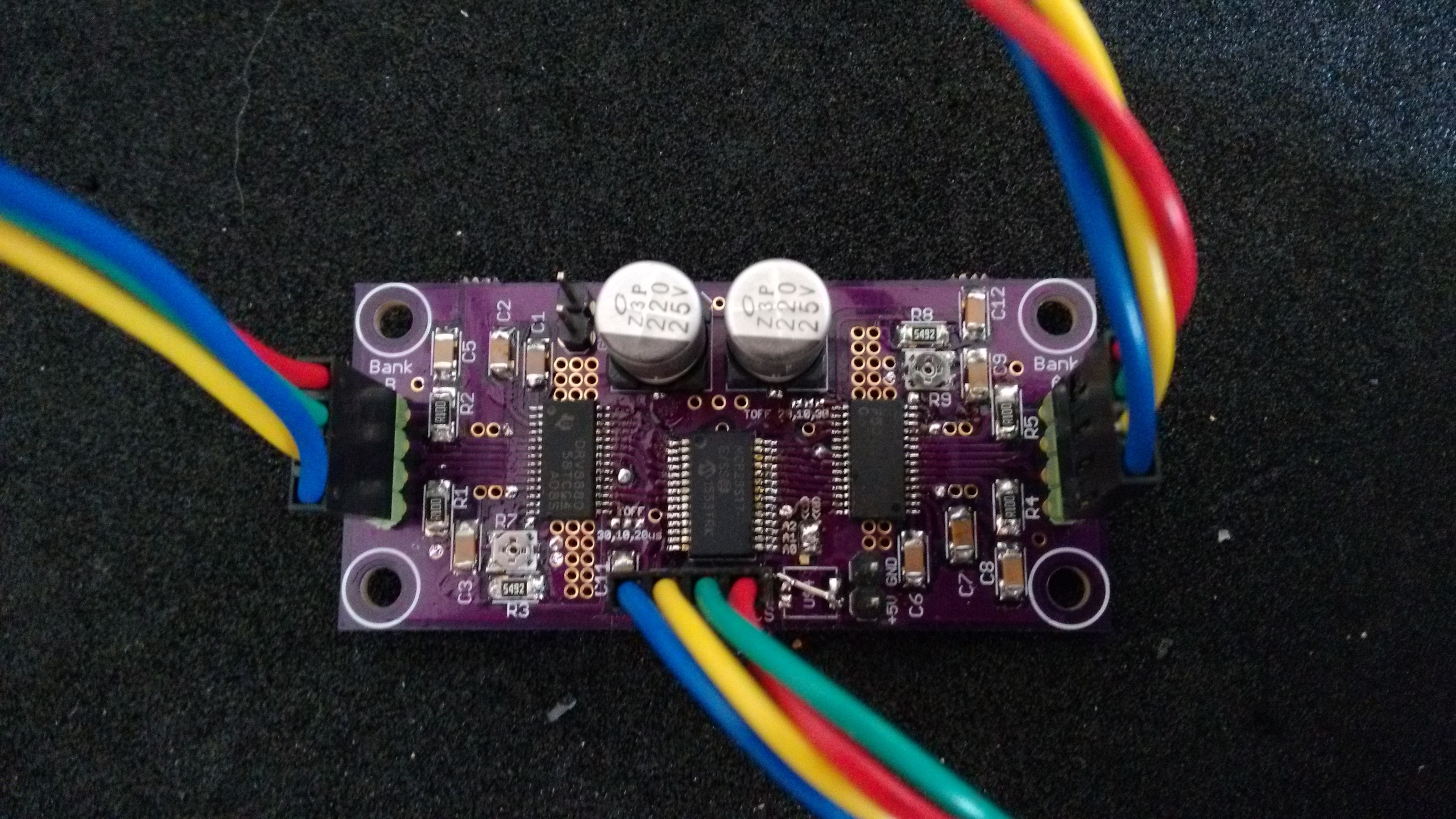
Dual Stepper board & TEC controller
06/26/2016 at 20:22 • 0 commentsNot much progress over the last month or so, i've been working on a more commercial project that has been taking my time. But there will be a few updates over the next few weeks.
The v2.0 dual stepper board is now up and running (gerber files, schematic and example Arduino code added to project, see links), so that's one more thing off the list.
![]()
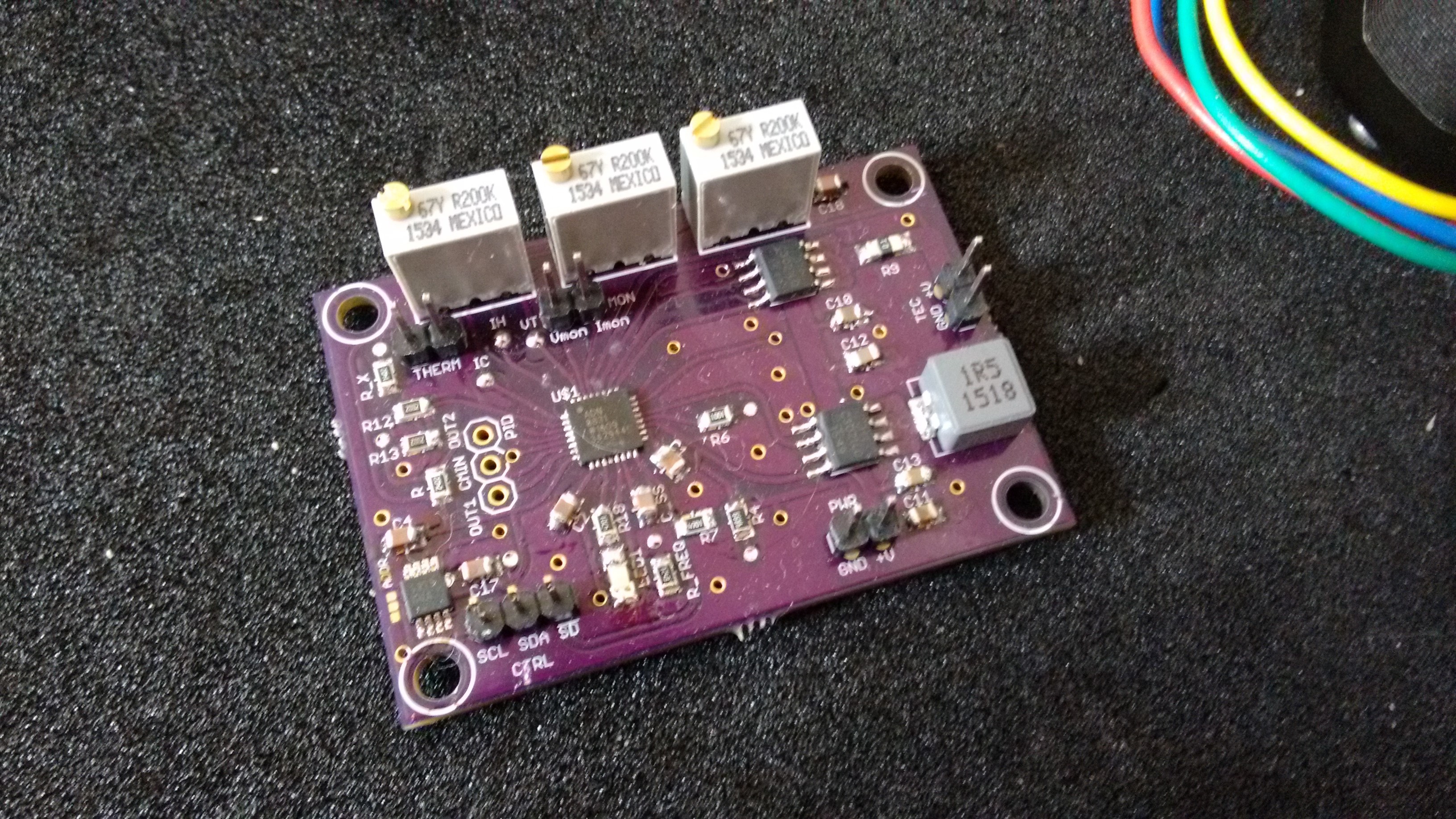
I've assembled the TEC board, and it is awaiting testing / tuning. The controller has a tuning network that needs optimising based on the specifics of the TEC, heat source and thermal mass. So I will cobble something to check that it works and re-evaluate when I have the physical hardware to get the correct settings. Here is a preview;
![]()
-
Quick update
05/18/2016 at 19:00 • 0 commentsI've submitted the new design for the TEC controller PCB to OSH for fabrication, so should get that back in a couple of weeks.
On the print head front, i've managed to get hold of one raspberry pi zero in the UK, but that will take a few weeks till its in my hands. Just managed to pickup one from adafruit including camera module to justify the shipping costs, so should be able to run some testing of the head using a laser diode dummy load.
With the increase in production hopefully the zeros will become more plentiful in due course.
-
TEC controller - testing
05/05/2016 at 21:42 • 0 commentsThe missing op-amp arrived fro mouser, and I've run testing on the TEC board, which can be found here; I2C TEC controller project.
-
SPI dual stepper controller update
05/03/2016 at 22:11 • 0 commentsSome progress has been made on the new SPI dual stepper controller board, update can be found here; SPI stepper controller project
-
Raspberry Pi breakout board update
05/03/2016 at 21:43 • 0 commentsI've detailed an update on raspberry pi zero breakout board here: Raspberry pi zero breakout project
-
Interfacing progress
04/21/2016 at 14:06 • 0 commentsI've built up the core functions on the arduino that control the following I2C sub-systems;
- Temp & humidity sensor - ok
- trigger laser DAC - ok
- x8 UV laser DAC - ok
- laser current monitor ADC - ok
- TEC temperature set point DAC - ok
- I/O extender & frequency generator - ok
- arduino direct pins I/O - partial
Next up is to design the parsing system to allow the functions to be called by the raspberry pi over serial link.
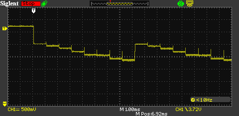
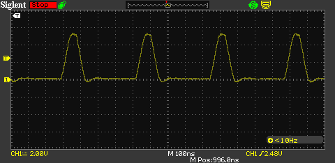
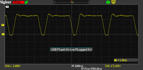
The clocking out of the frequency generator has been modified to give a better behaviour for the FIFO read out. Originally I was using the non-inverted output from the AD9850, assuming that the waveform would be symmetric.
However, it seems that because I am using a 3.3v drive clock (DSC1001 - MEMS 125MHz oscillator) that there is bias, because this is less than the expected 5v, which in this case is a good thing, as it means that there is a greater 'on' time from the inverted output. Resulting in the FIFO being held at 'read' longer than it is 'off' whilst clocking to the next bit.
Non-inverted output![]()
![]() Inverted output
Inverted output -
Focus uStepper motor
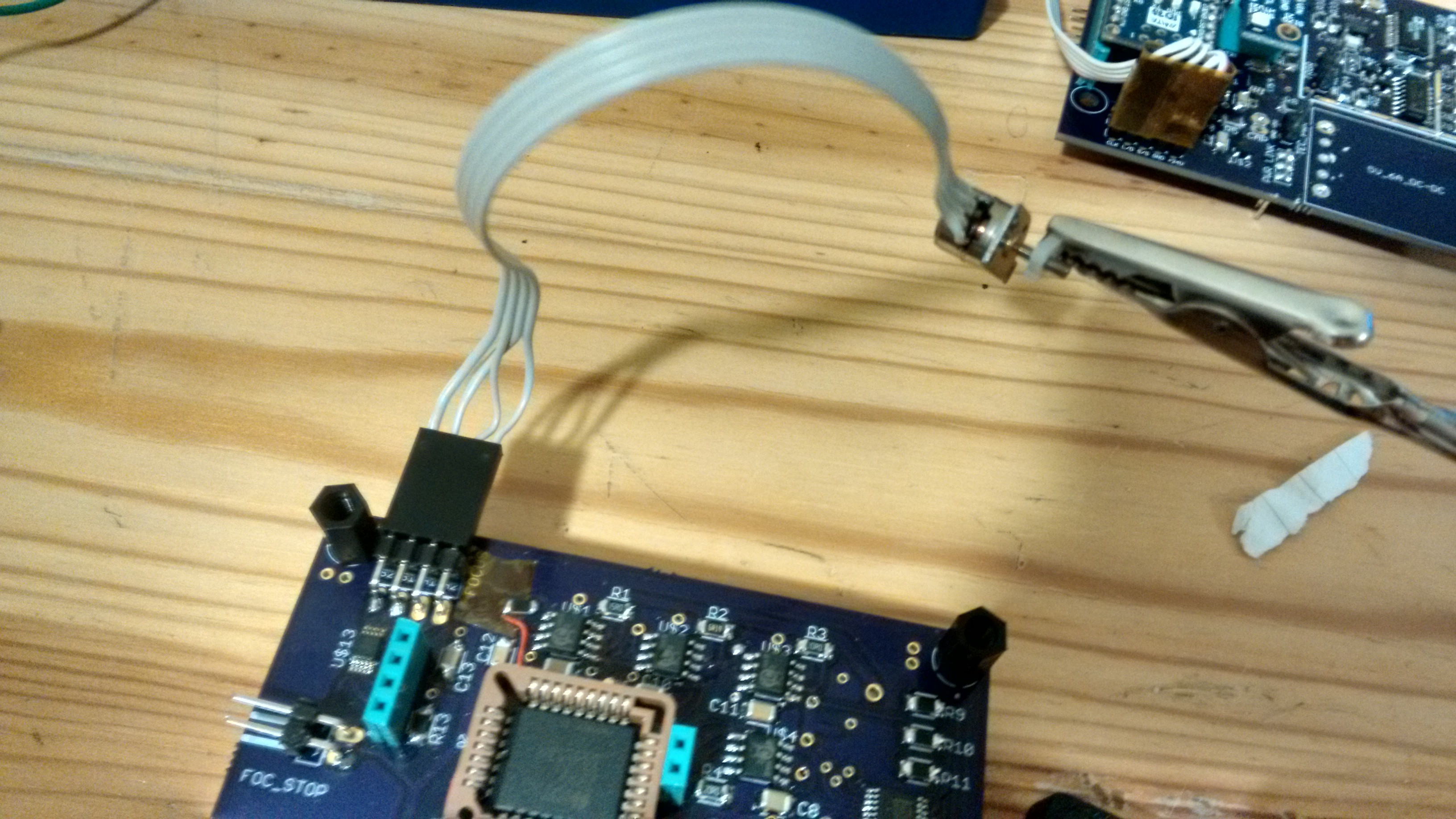
04/19/2016 at 02:04 • 0 commentsThe focus mechanism will be driven by a micro stepper motor, the driver IC for this is a LB1935FA - a bipolar stepper driver, this requires two logic lines to set the stepping logic 00, 01, 11, 10, etc. or the reverse sequence for reverse, and one for enabling the system (this keeps the current off when not required).
As can be see (upper left, below the connector) the driver is very small, so could be useful for all manner of different projects.
The motor i'm using is 8mm x 8mm diameter, so quite large compared to many available on eBay.
I've found that a 1us coil activation time to be optimal, this gives a nice smooth response. Higher delays seem to be more jarring / noisy.
![]()
Direct UV Printer for Alternative Photography
Design of a UV printer for making exposures of Alternative Photography prints, direct from a digital image
 David Brown



 Inverted output