ken.do
-
Sensors
09/29/2017 at 19:29 • 2 commentsThis is a list of possible sensors for inclusion
Gyro - ideally, this robot should be able to walk on a grade and maintain the upright orientation of the hub. Useful for side-grades and inclines, keeps camera or other equipment on the level.
Optical flow sensor - this would allow the robot to track actual movement (for measuring slippage and closely estimating location)
Pressure sensor - incorporated into the leg joint(s) to signal ground/other contact and with the appropriate sensor, measure amount of force applied to each 'foot'
Ultrasonic distance sensors - for obstacle avoidance and relative positioning
Camera(s) - also for obstacle avoidance and relative positioning, (obstacle recognition?)
-
Build - Step 7
09/03/2017 at 00:40 • 0 comments7. Route cables
![]()
Now all that is left is hooking your servos up to a control board. Battery and control board mounting configuration is up to you!!
-
Build - Step 6
09/03/2017 at 00:40 • 0 comments6. Attach foot to mid leg
Using the shallower nub, follow the procedure for attaching the mid leg to the hip. it is important that the rounded part of the foot is up relative the top of the main body.
![]()
![]()
Again, seat and secure horn to both servo and foot.
-
Build - Step 5
09/03/2017 at 00:39 • 0 comments5. Attach mid leg piece to hip joint
Insert the fat end of one of the deeper nubs into the bottom of the mid leg piece. Repeat the procedure for attaching the hip joint to the main body, but using the mid leg piece instead of the main body. Don't forget to seat the horn on the servo and attach to both the servo and the hip joint. (I didn't attach to hip joint because I ran out of screws!)
![]()
-
Build - Step 4
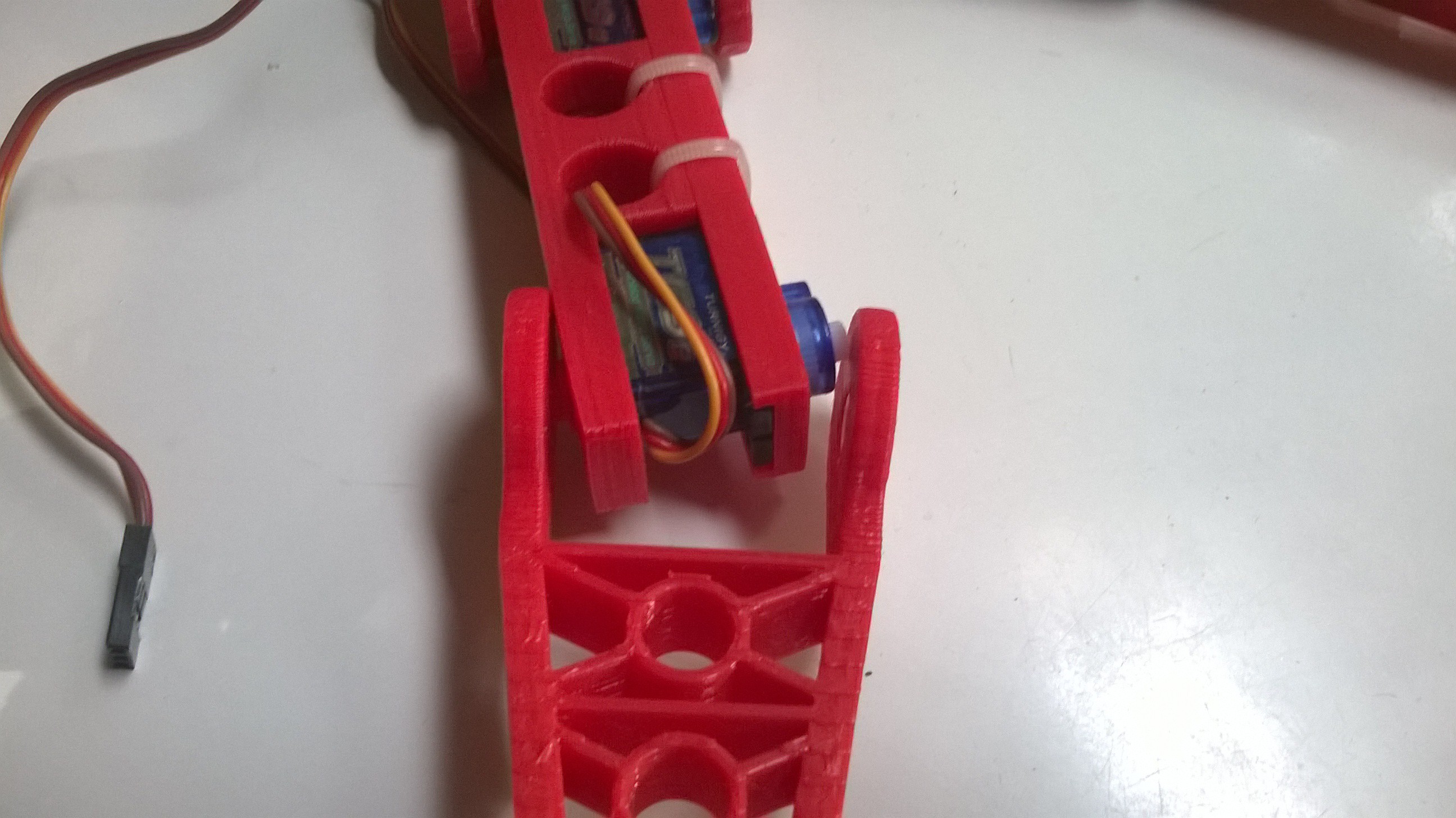
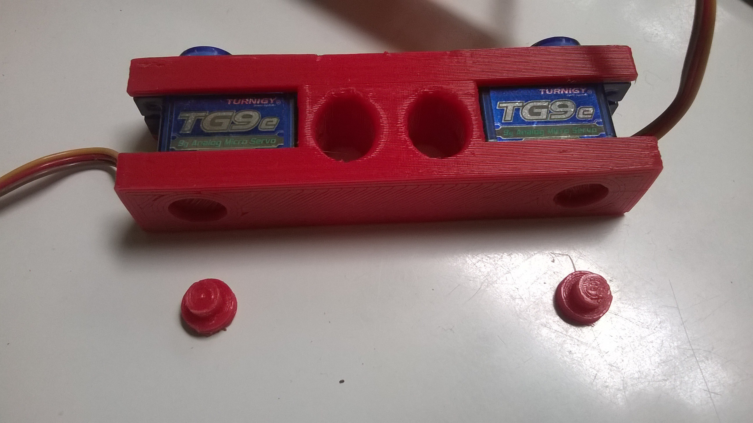
09/03/2017 at 00:39 • 0 comments4. Assemble mid leg pieces
Again, insert servo bottoms (both at once) into the receptacles on the mid leg piece, being careful to avoid pinching the control wires. Then place and secure the other half using either zip ties or screws.
![]()
![]()
-
Build - Step 3
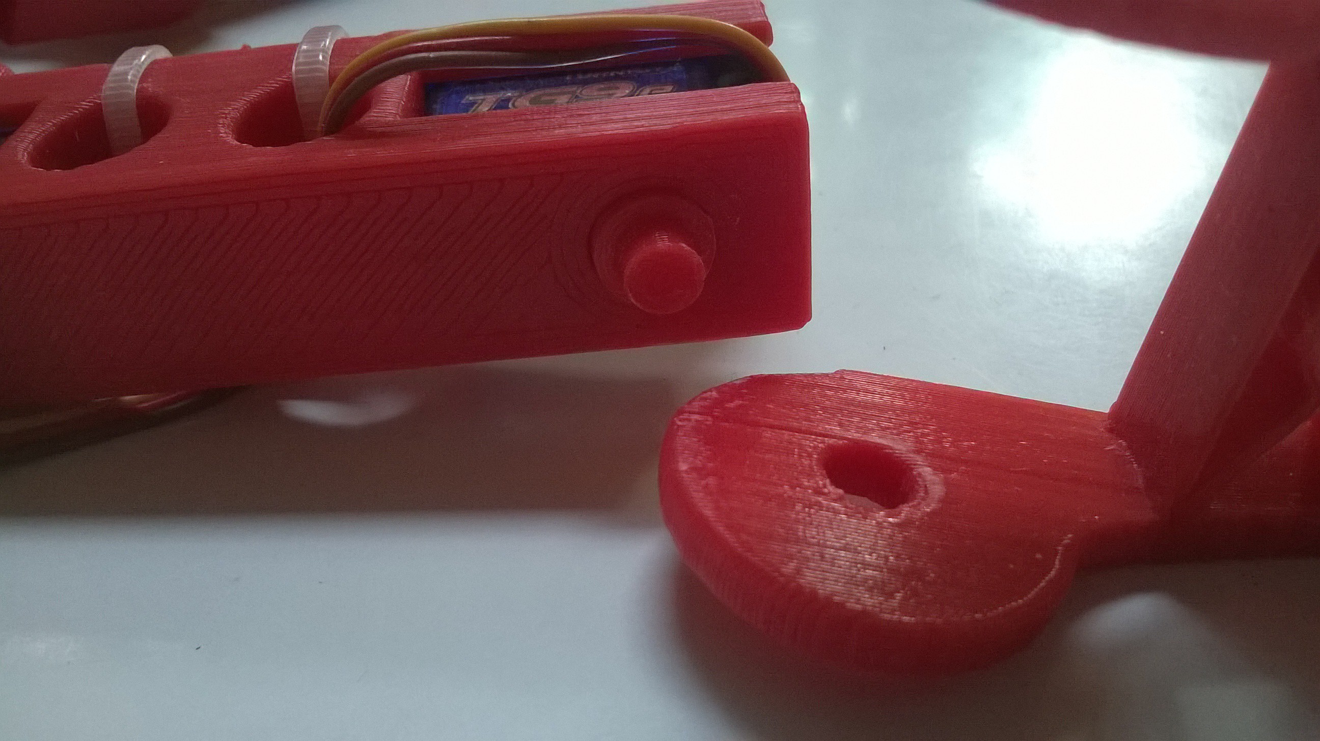
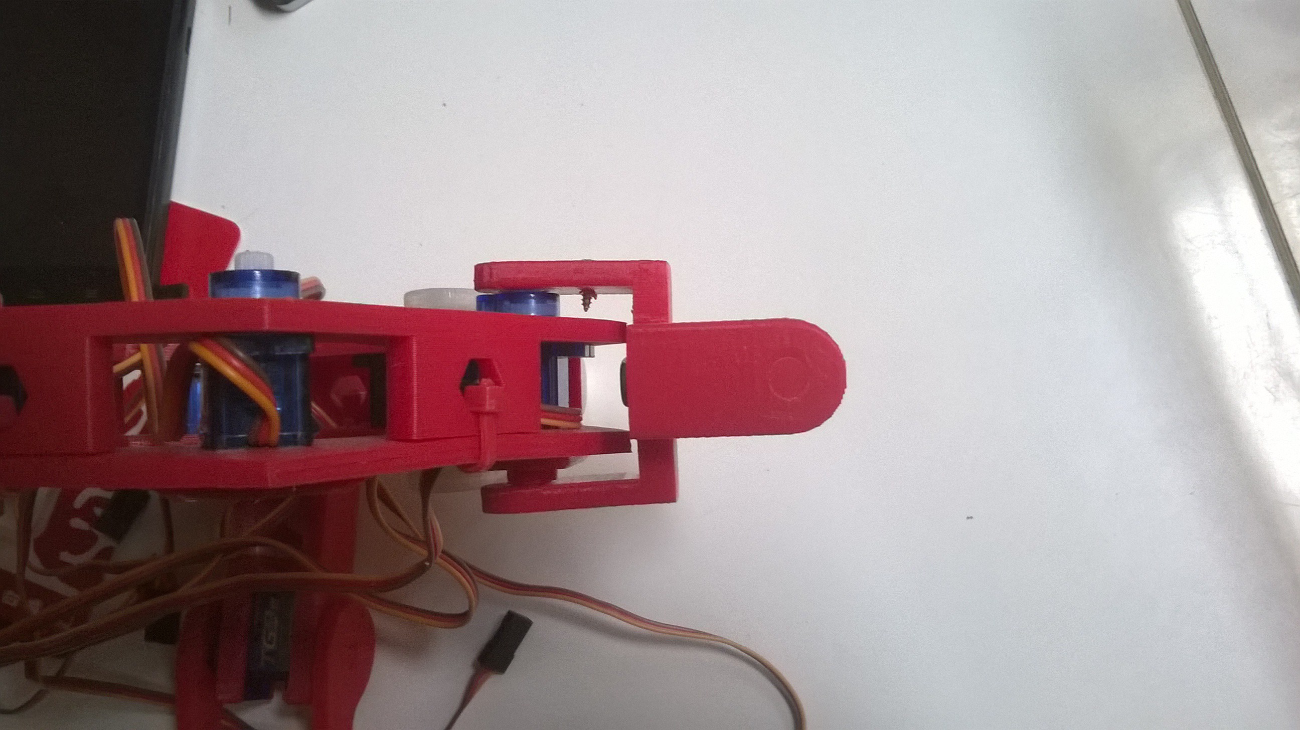
09/03/2017 at 00:39 • 0 comments3. Add hip joint to main body frame
Insert a nub with the deeper wide section, narrow section first into the inside of joint.
![]()
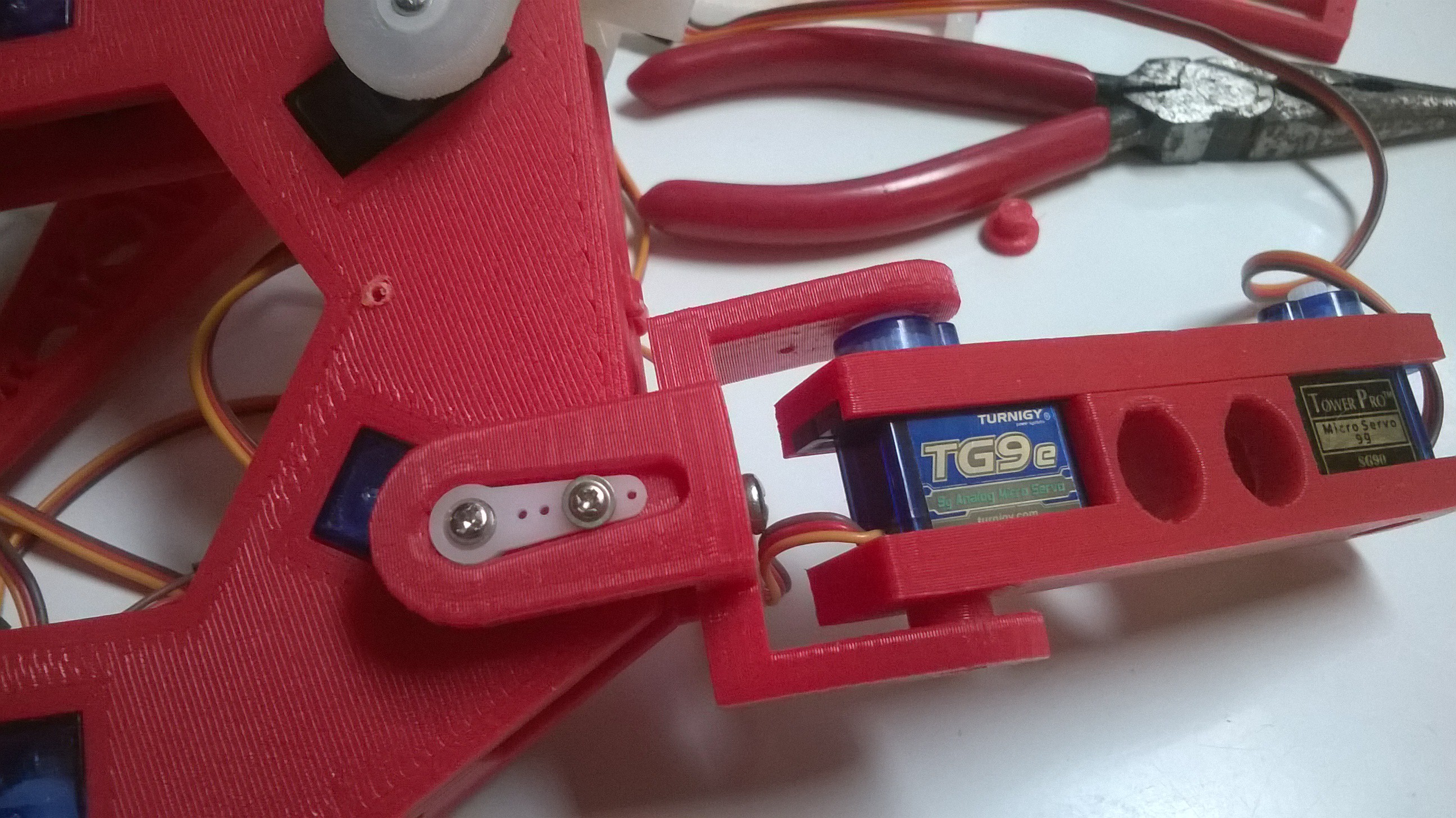
The main body frame has a bevelled section for the nub end to slide up and into place. Insert and attach servo horn onto the hip joint, flat side out, seating it securely to the hip and the servo in the main body. I used the screws provided with the servos, but needed to drill out one of the horn holes to accomodate the screw size.
![]()
![]()
-
Build - Step 2
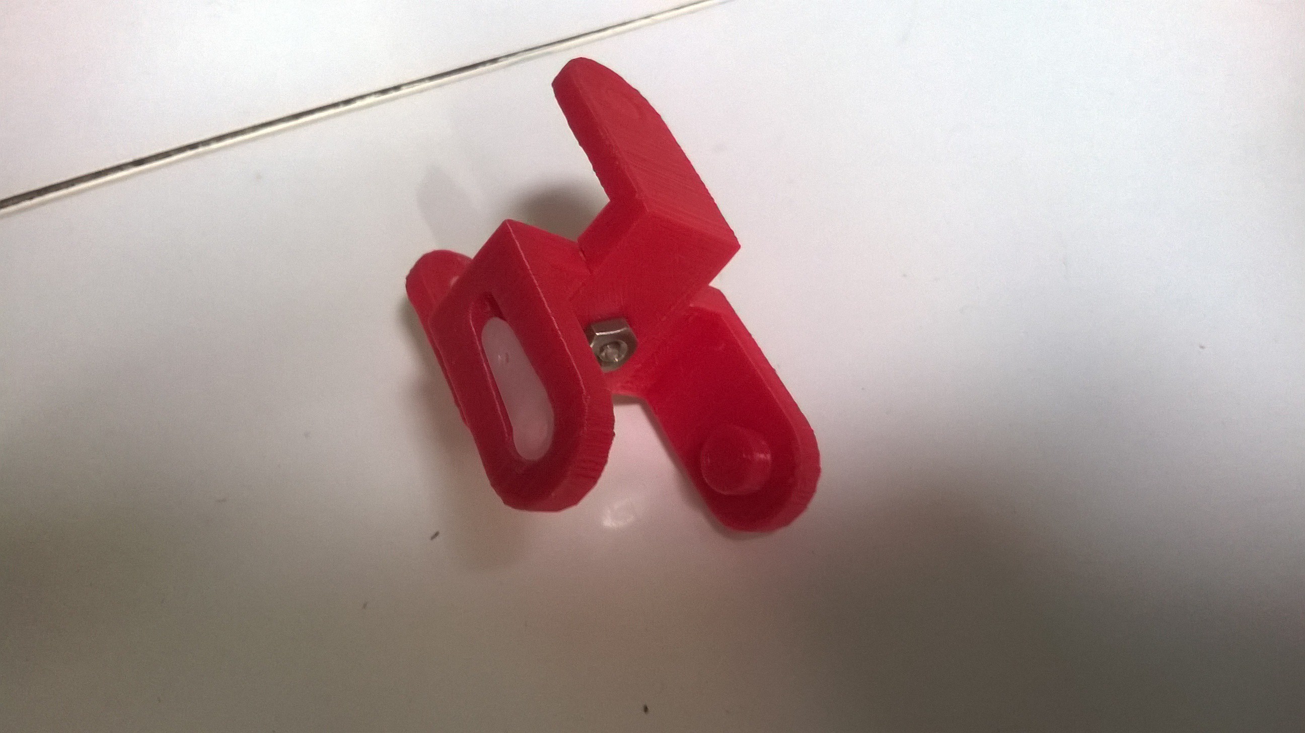
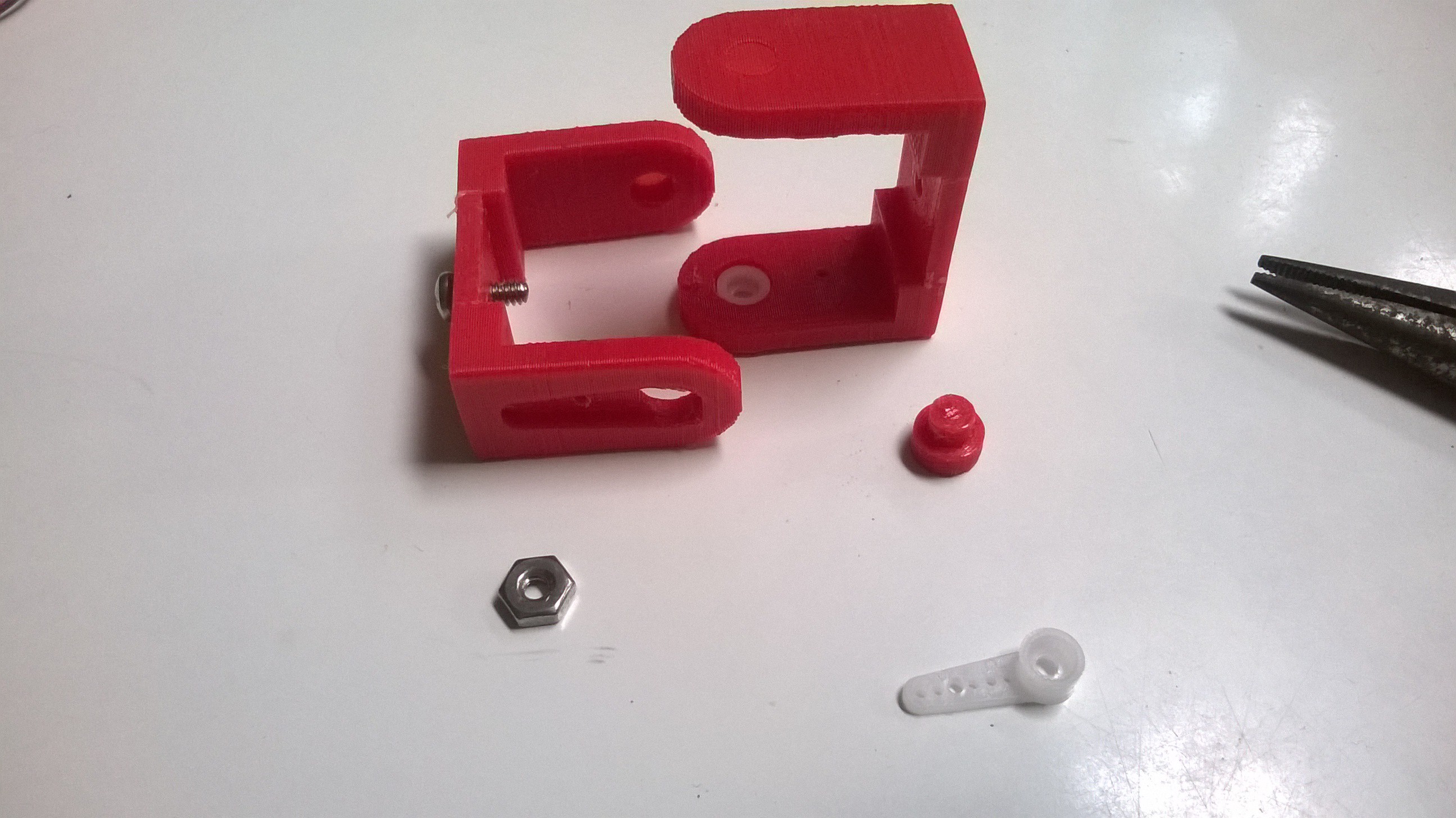
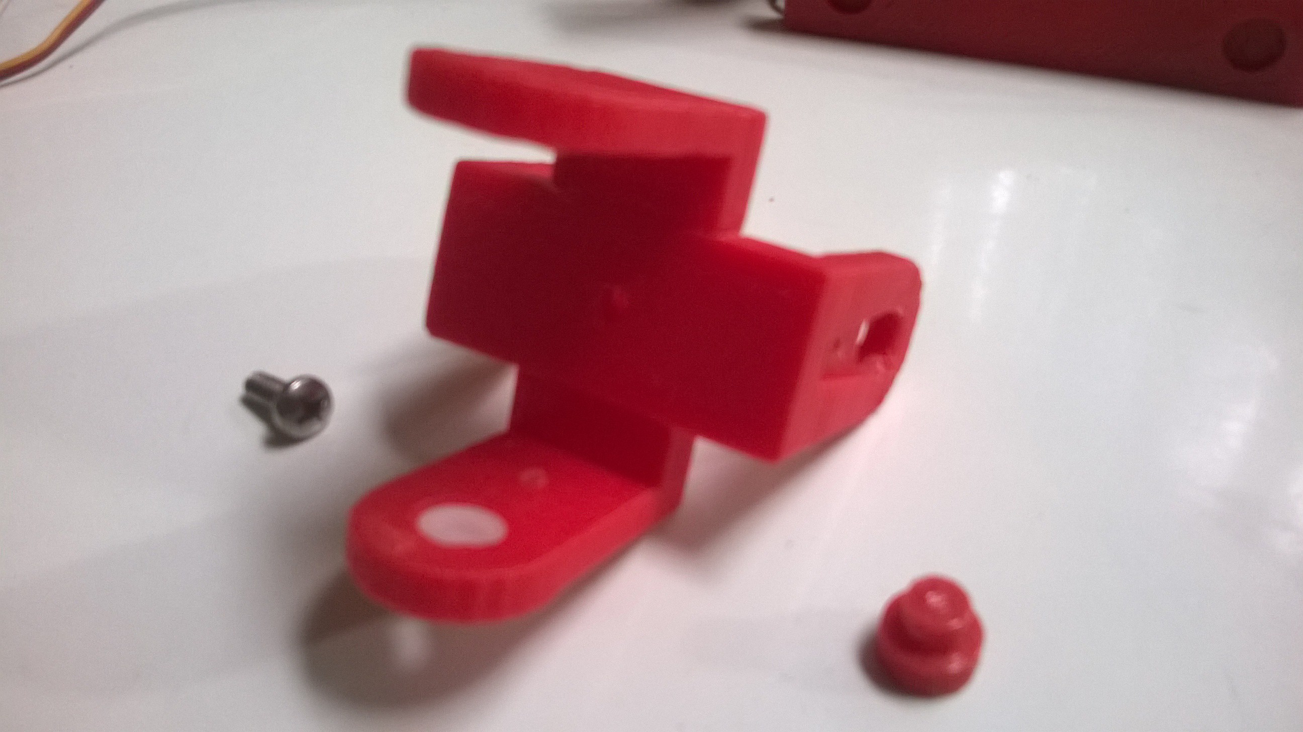
09/03/2017 at 00:38 • 0 comments2. Assemble the 'hip' sections
Two identical hip sections are placed together 90 degrees from each other.
![]()
![]()
Attach them through the center hole with a 4mm x 1/2 inch-ish machine screw and nut.
-
Build - Step 1
11/24/2016 at 22:15 • 0 comments*note* The longer nubs may not be necessary any more due to tighter printing tolerances. If the shorter nubs work, use them in place of the longer ones.
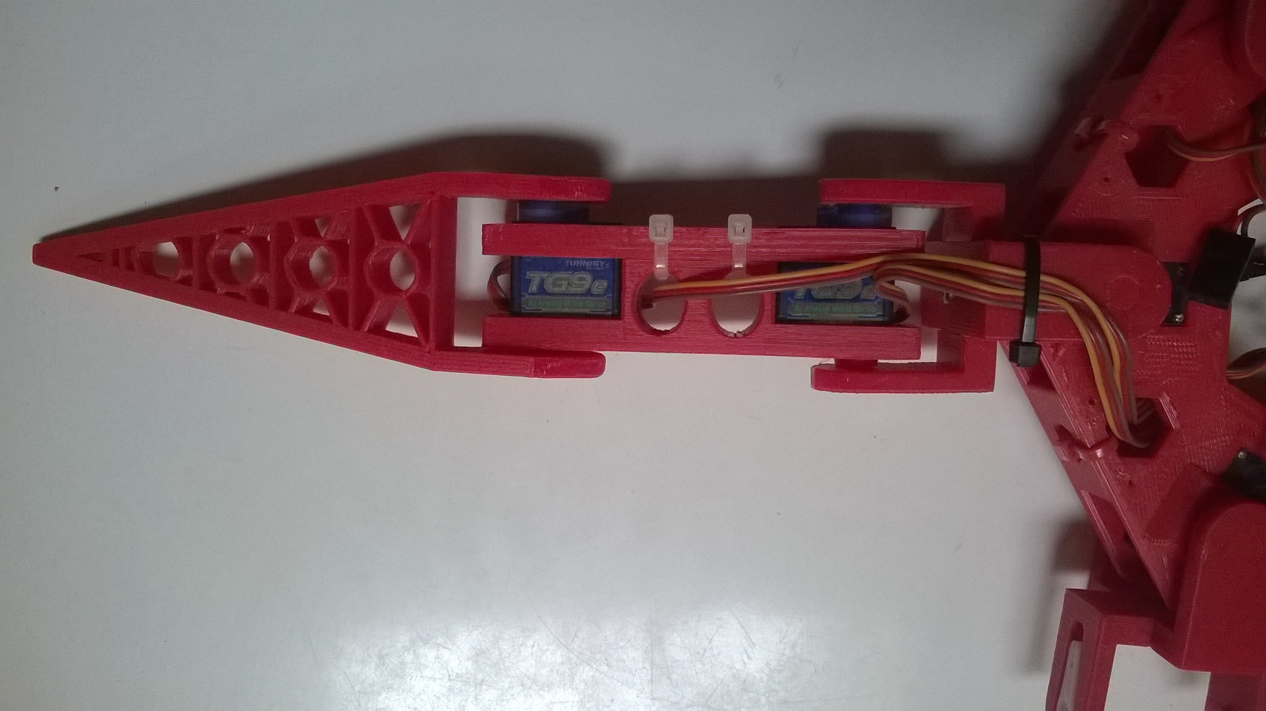
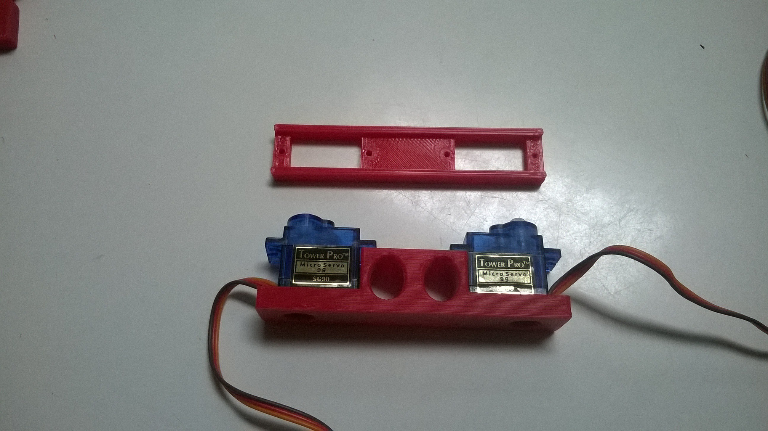
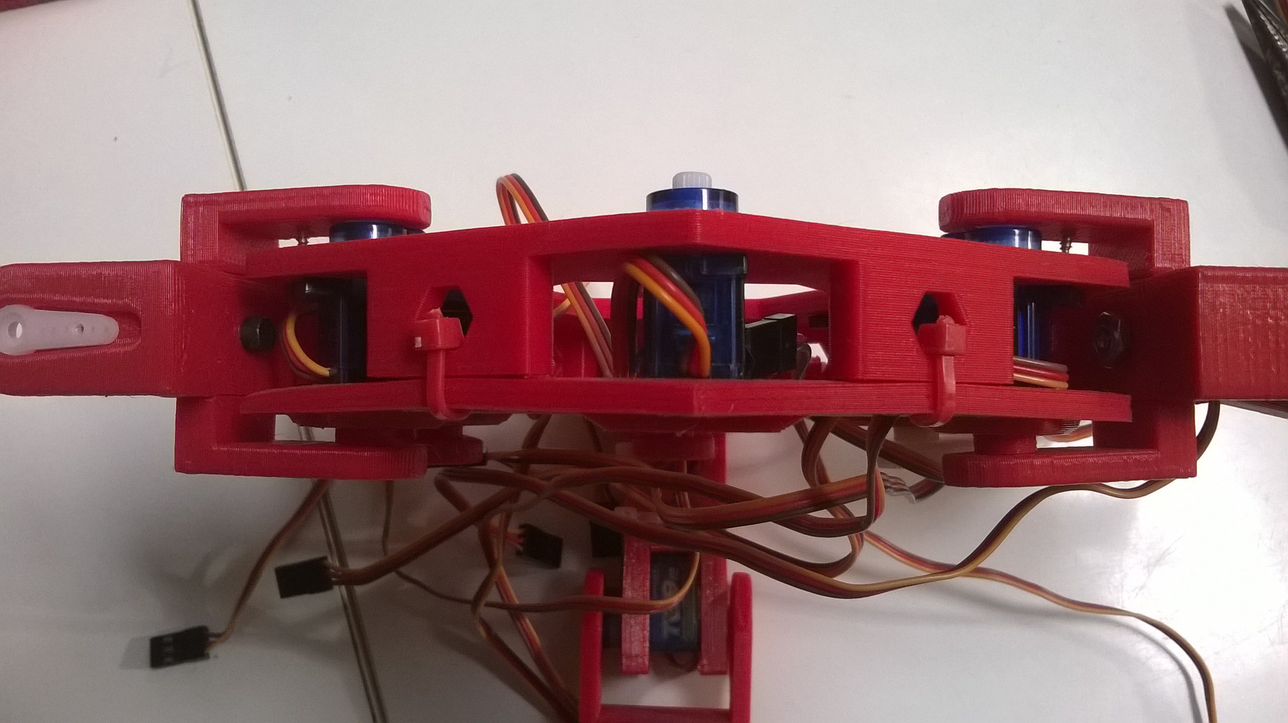
1. Assemble the main body frame:
To assemble the main body frame, servos are inserted in each of the 6 receptacles on one half of the frame and then sandwiched with the other half. Secure the halves with zip ties, or screws.
![]()
18 DOF High-Flotation Hexapod Robot
Six legs, 18 servos, with optional high-flotation mode. My first project that combined robotics and 3D printing.