Tom Meehan
-
References for Universal Glucometer
07/04/2016 at 02:39 • 0 commentsThis is a partial list of references I have used so far in researching the design and operation of glucometers, glucose measurement techniques, strip design, etc. (I continue to find and read new resources).
I've included links to articles or abstracts whenever possible.Microprocessor manufactures (designs, application notes, etc):
- TI-microcontrollers in bG Meters
- Maxim Integrated: Blood Glucose Meters-tutorial
- Freescale: Glucose Meter Fundamentals and Design
- Microchip Glucose Meter Reference Design
Related Projects (on Hackaday and elsewhere)
- Arduino Blood Glucose Shield (There is a recent write up of this project on Hackaday.com)
- Glucometer - Built from OpAmps and a Microcontroller
Research Papers
- Performance of Glucose Dehydrogenase– and Glucose Oxidase–Based Blood Glucose Meters at High Altitude and Low TemperaturePerformance of Glucose Dehydrogenase– and Glucose Oxidase–Based Blood Glucose Meters at High Altitude and Low Temperature
- Heller A., Feldman B. Electrochemical glucose sensors and their applications in diabetes management. Chem Rev, 2008, 108:2482-2505.
- Newman J,Turner A. Home Blood Glucose Biosensors: A Commercial Perspective. Biosensors and Bioelectronics, 20(12):2435-2453
- Bioelectronics for Amperometric Biosensors
Other directions for measuring Blood Glucose
- Goa, Qu, Li, Shrestha, Song. 2014. Development of amperometric glucose biosensor based on prussian functionalized TiO2 nanotube arrays. Scientific Reports November 4, 2014
- Alizadeh, Mirzagholipur. 2014. A Nafion-free non-enzymatic amperometric glucose sensor based on copper oxide nanoparticles-graphene nanocomposite. Sensors and Actuators B: Chemical 198
- Printing Low Cost Glucose Test Strips on Paper - this is an amazing idea and works using custom filled inkjet cartridges in a standard inkjet printer!
Patents on Blood Glucose Test Strips
US Patents
- #5,563,042 Oct. 8, 1996 Whole Blood Glucose Test Strip (Lifescan)
- #5,426,032 Jun. 20, 1995 No-Wipe Whole Blood Glucose Test Strip (Lifescan)
- #6,241,862 B1 Jun. 5, 2001 Disposable Test Strips With Integrated Reagent/Blood Separation Layer (Inverness Medical Technology, Inc.,)
- #7,112,265 B1 Sep. 26, 2006 Disposable Test Strips With Integrated Reagent/Blood Separation Layer (Lifescan)
- #5,951,836 Sep. 14, 1999 Disposable Glucose Test Strips and Method and Compositions for Making Same (Selfcare)
- #7,250,105 B1 Jul. 31, 2007 Measurements of Substances in Liquid (Lifescan)
Patents Related to Standard Solutions to Calibrate Strips/Meters
- Liquid glucose control solution and process of making the same WO 1993021928 A1
- Glucose measurement control reagent and method of making the same
- Glucose reference control for glucose test strips
_______________________________________________________________________
This is by far not a complete list, that is something I am slowly building up as I sort through my papers and textbooks.
-last updated 9/13/16
-
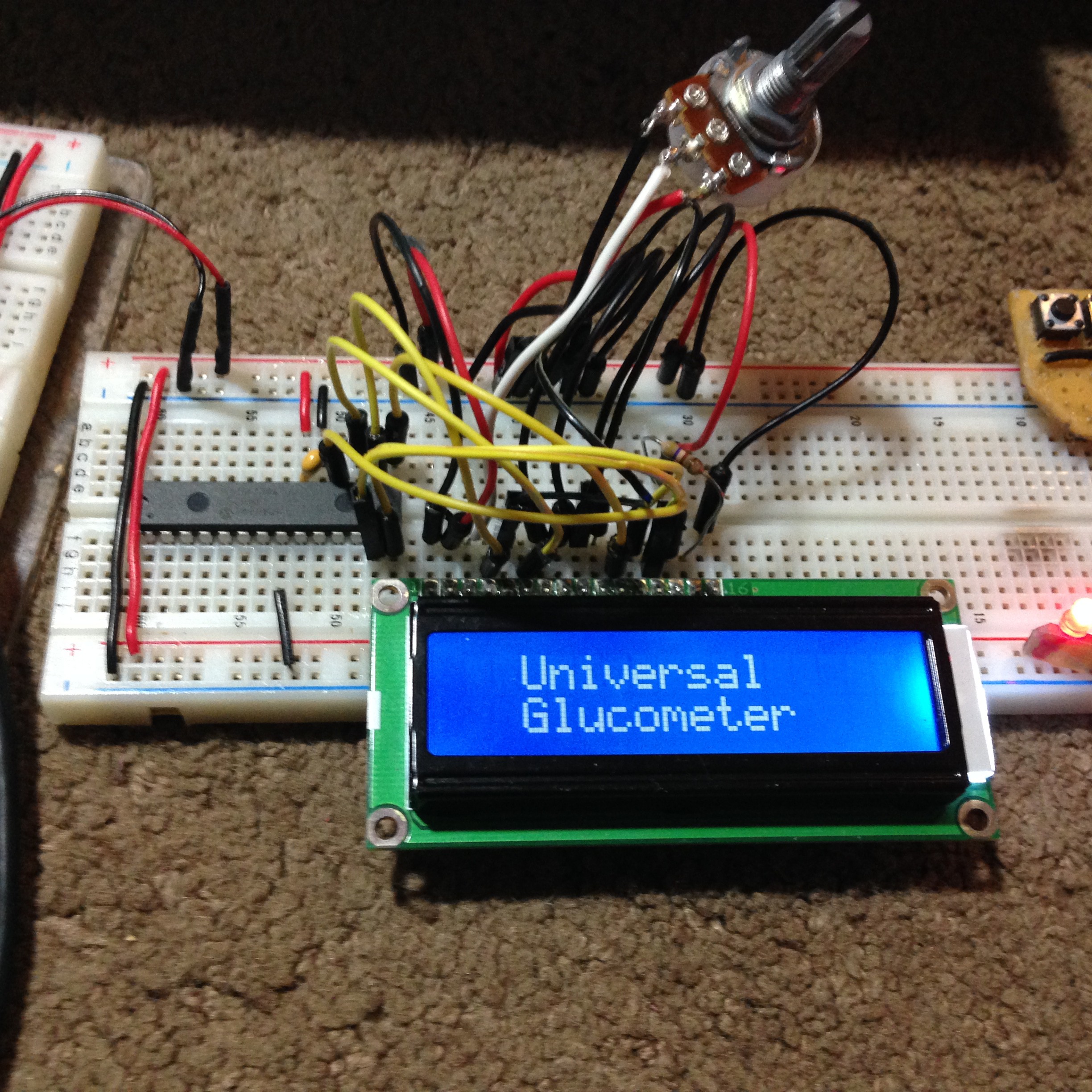
PIC16F1786 now working with standard 16x2 LCD
07/02/2016 at 04:06 • 0 comments![]()
It took me a bit of trial and error but I finally got a standard 16x2 LCD display to function with my target chip (PIC16F1786).
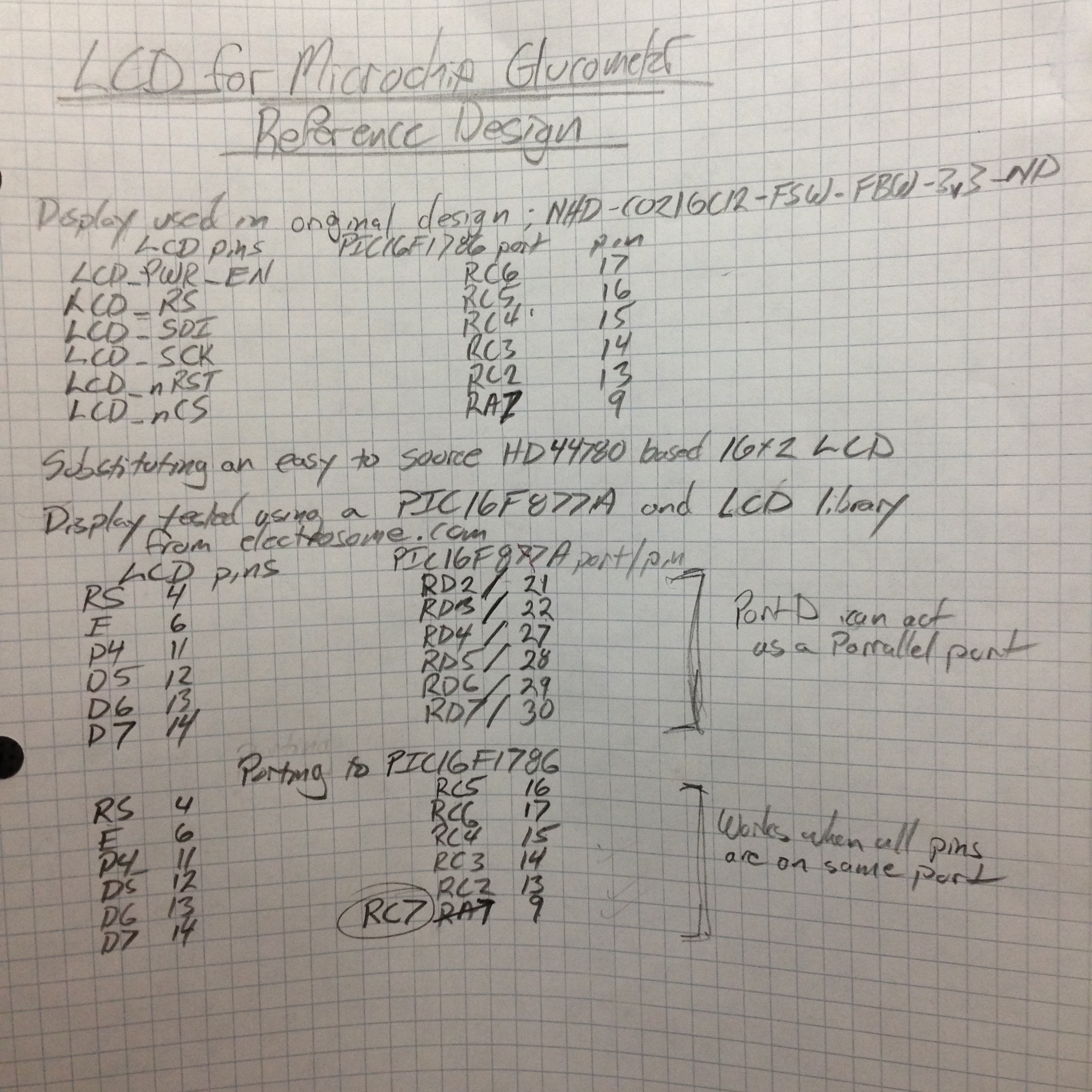
First I had to figure out the pin connections from the LCD to the PIC.
![]()
Initially I tried utilizing the same pins used in the Microchip reference design. It wasn't quite that easy, of course. Then I thought - maybe the logic is reversed for the RS pin - so I changed it in the lcd_1.h file. Still no luck. Finally I dug into the datasheet for the PIC16F877A to see what the RD port functions were (turns out it is a parallel port register). Then I looked at the datasheet for the PIC16F1786 to see what ports had a similar function, not as easy as I thought. In the end I decided to try using another pin from the RC register (that is not used in the reference design), changed my "#defines" in my program to correspond... and Eureka it worked.
The "lcd_1.h" file I used came from electrosome.
-
Success with PIC16F1768
06/27/2016 at 08:25 • 0 comments![]()
This "Hello World" was just about as tough as the one for the PIC16F877A. Took a whole lot of trial and error (mostly error).
What Config bits need to be set
Setting up Internal Oscillator
Making it easier to use " __delay_ms(1000);". I'm at a distinct disadvantage since I'm fairly new to programming in C and even newer to programming PIC microcontrollers. So, setting configuration bits has been a bit of an adventure.
Links to Datasheet and to XC8 compiler guide
-
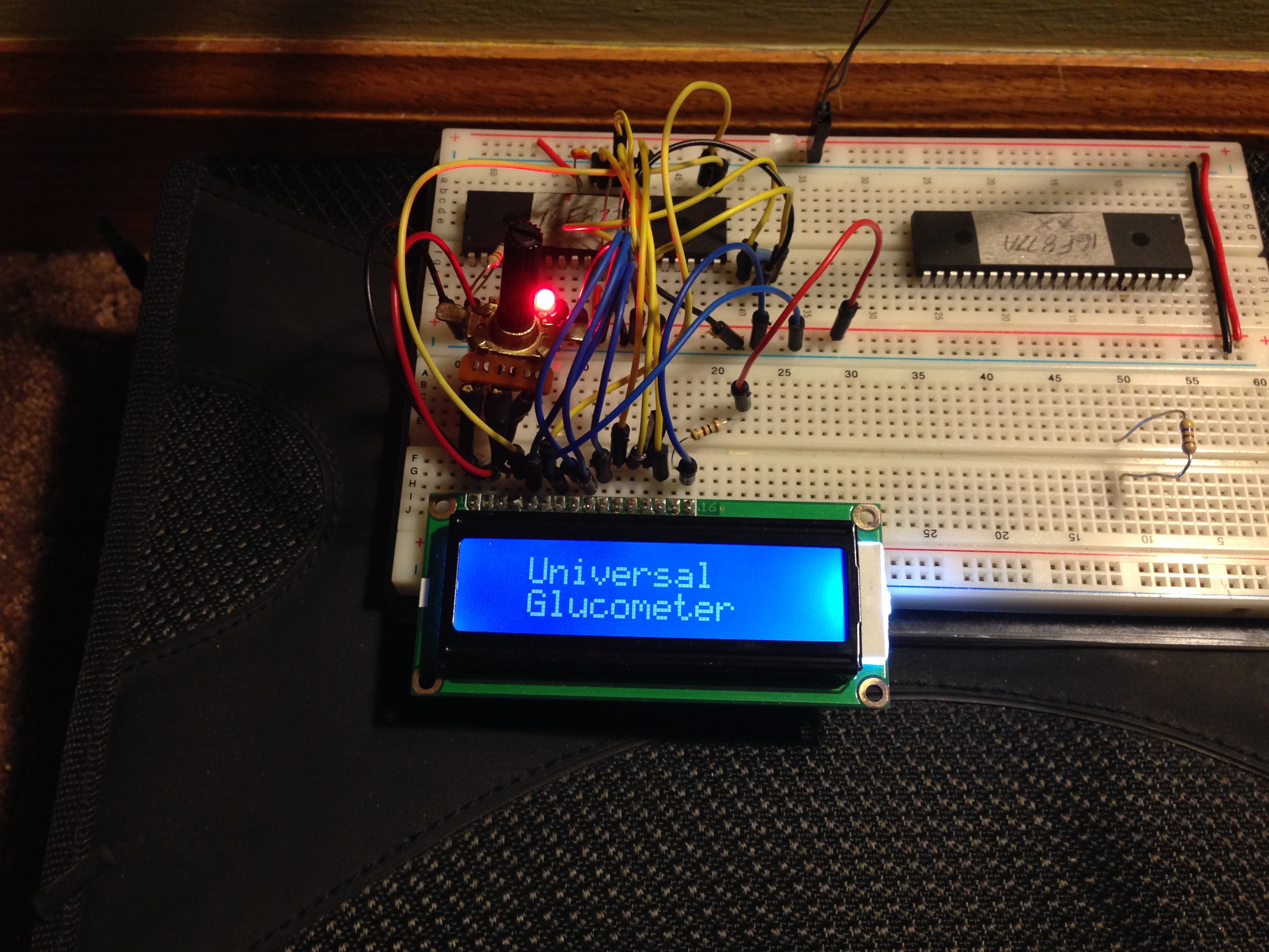
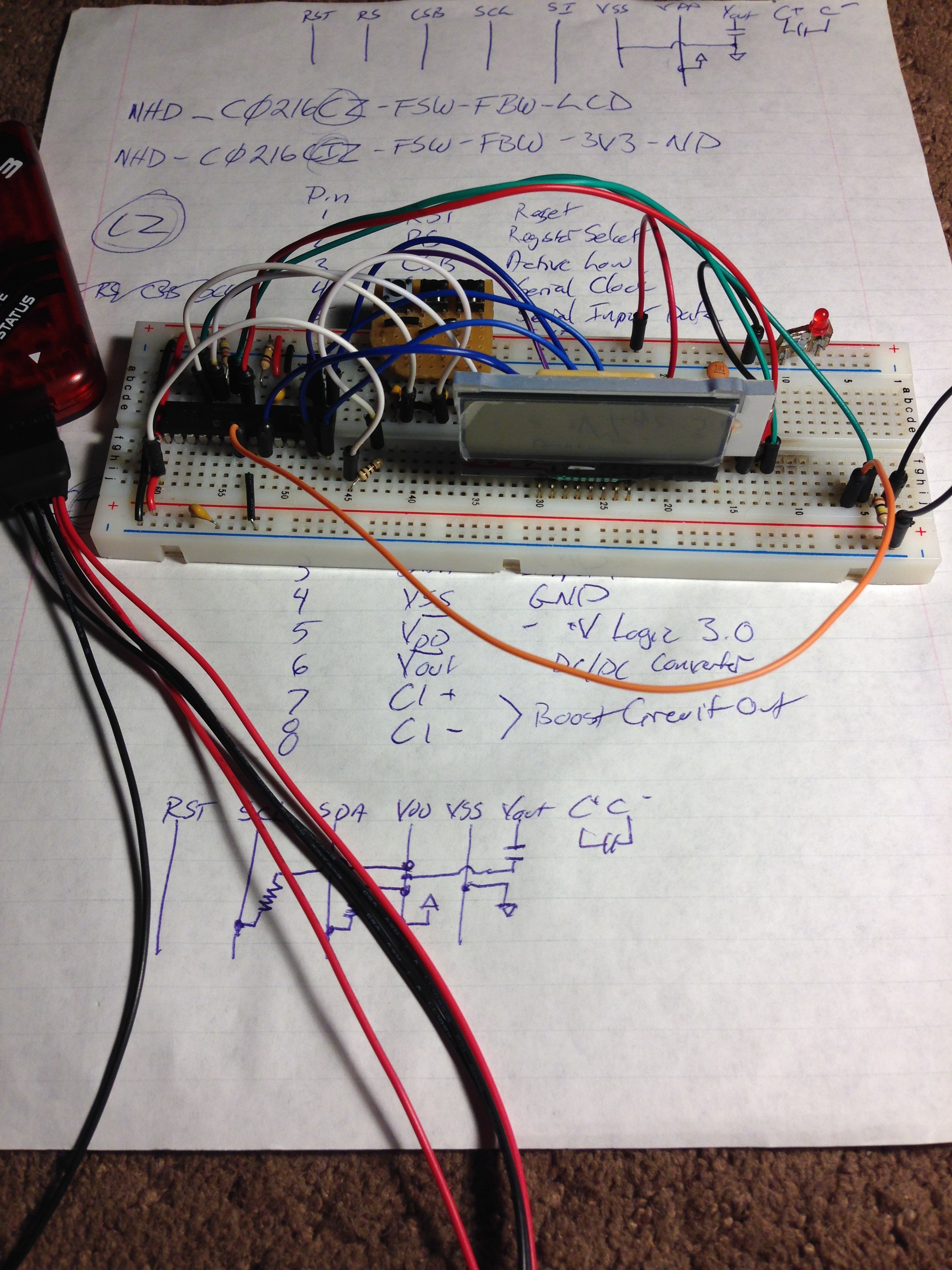
HD44780 LCD Display working
06/27/2016 at 08:13 • 0 comments![]()
It took a bit of testing and research but I finally got an HD44780 controller, 16x2 LCD display functioning with the PIC 16F877A, now I need to get it to function with the PIC16F1786 (my target chip). The C-code from Microchip demonstrating a glucometer design used a harder to source 16x2 LCD display, I would have started with that but couldn't get it it. So, I decided to work with a more standard 16x2 LCD. My ultimate goal is to use a Nokia 5110 LCD since it is a bit more compact and fairly inexpensive and easy to source.
I've bread boarded an HD44780 16x2 LCD, connected to the PIC16F1786. I'm currently editing code to test out the LCD.
-
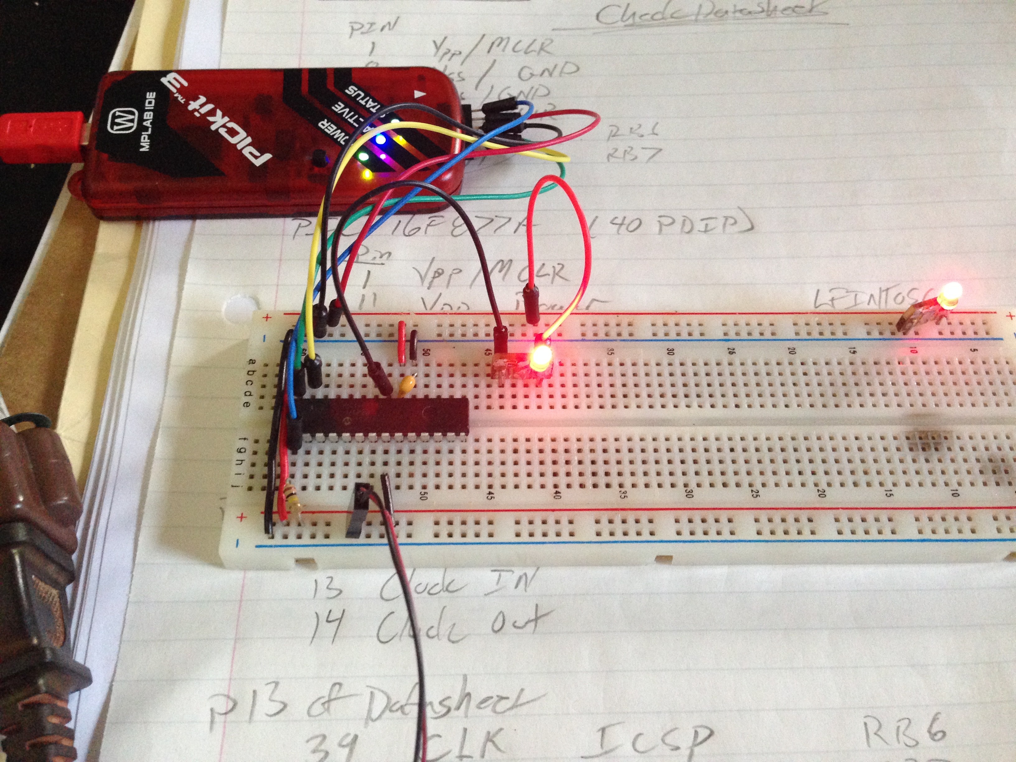
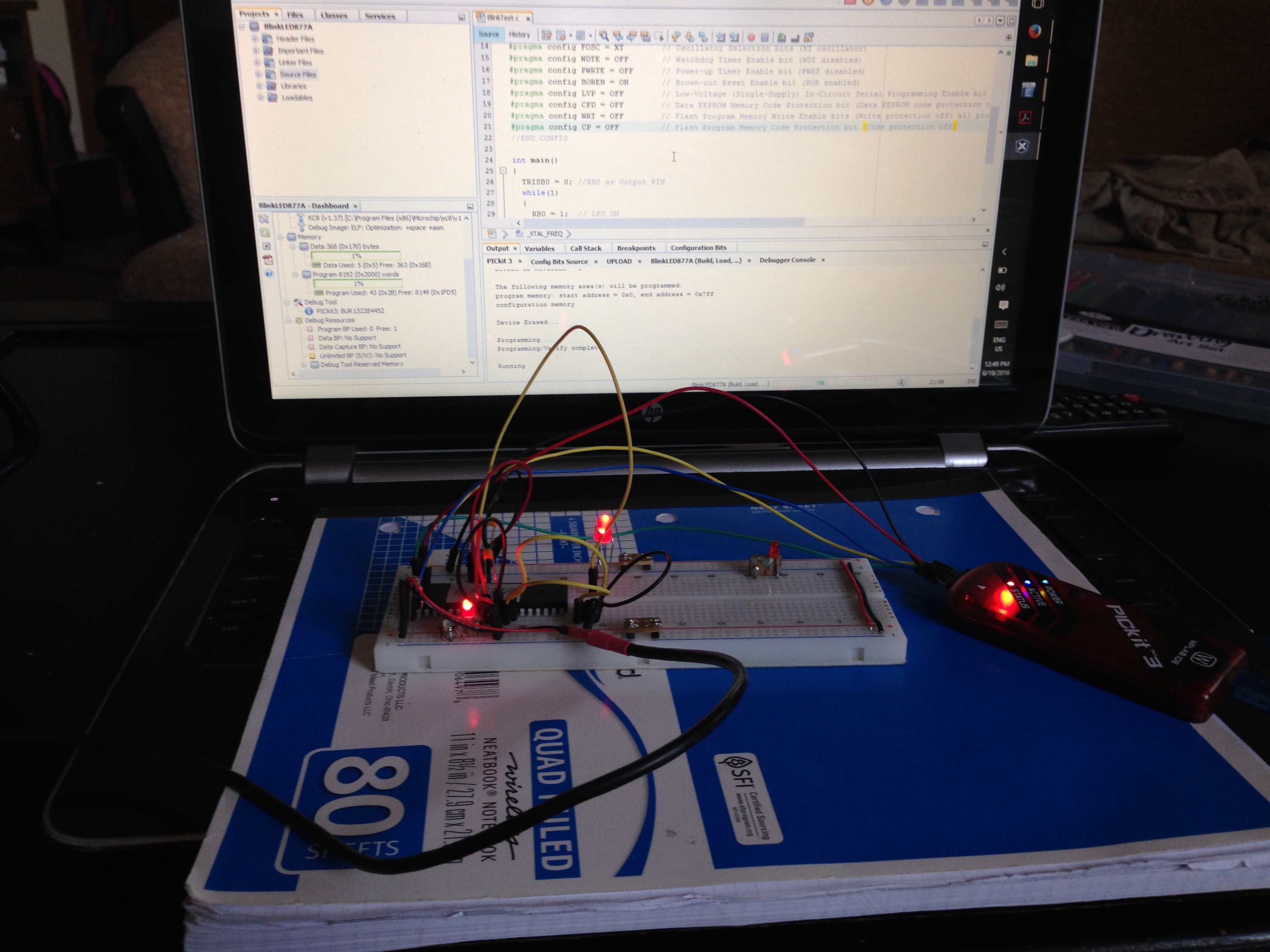
Hello World
06/19/2016 at 18:14 • 0 commentsTaking a step back I decided I needed to ensure my programmer (PICkit3 clone) actually works and that I can actually upload programs. When I ordered the last LCD screen I also got a few PIC16F877A chips since I have some books that use them for learning to code in C for PIC's.
It's taken me a few days of reading, trial, and error but I've finally gotten an LED to blink (pretty impressive right!).
Next step is attaching and sending text to a standard 16x2 LCD.
![]()
-
Pushing Past Obstacles
05/25/2016 at 05:57 • 0 comments![]()
The LCD in Microchips Reference Design has a lead spacing I haven't seen before. So... I I used some strip board to make an adapter so it can fit into a standard 0.1”pitch breadboard. While adjusting the angle for better viewing I cracked the glass so I placed a new order for:
- new LCD
- additional capacitors (I thought I had all the ones I needed but found I missing a few)
- another PIC from the same series (16F1779 that has more memory and additional IO pins so that when the time comes I'll have additional pins for buttons for strip selection and more IO pins for the MultiStrip port - that I'm working on)
- some other PIC's to learn and experiment with
- Running through information in a few books, etc, to better learn PIC programming (C and Assembly)
I've finally gotten the reference/base coder from Microchip to compile without any errors, and finished bread boarding the reference design (well.. mostly, see below).
While finishing wiring the bread board I found that I have the incorrect LCD display. I ordered, and have, the C0216CiZ instead of the C0216CZ LCD display (it seems that now few suppliers carry the CZ and instead only have the CiZ display – both are 16 x 2 LCD displays but they are much different in pin out and use different protocols). There seems to be some code libraries for more standard 16 x 2 LCD displays, so I will attempt to implement them instead – since it will be easier for other people to replicate my final design.
Having never worked with PIC's before (only Arduino's and AVR's), editing and adding to code is challenging so far – but I am working at it every day and making steady progress.
-
Setup and code editing
04/30/2016 at 03:04 • 1 commentI received my parts order, including a PIkit3 (to program and debug the PIC microcontroller).
- Did forget a few capacitors, which I can get locally.
- Ordering a new LCD - since I dropped the current one.
- Using the regular 16F1786 (instead of the 16LF1786 - which seems to be unavailable anymore).
Downloaded and Installed MPLAB X IDE
Downloaded and Installed C-compiler for 8 bit PICS – XC8
As expected, had a few minor problems in setting up MPLAB X IDE but I got it figured out. Imported Reference Design Code into MPLAB X IDE. So far I've fixed a few errors that prevented the code from compiling - currently getting error that it doesn't recognize VREGCONbits.
Beginning a strip dissection to map it's pinout. I'll post up pictures as soon as I'm done.
-
Start of Build
04/22/2016 at 06:30 • 0 commentsMy first step is to put together Microchip's reference design on breadboard. All the parts I don't already have (PIC, LCD display, temp sensor, etc.) should arrive over the weekend, or Monday at the latest.
Then I'll be able to really begin to make changes/additions to the code and test them out.
Universal Glucometer
Did your test strips just get more expensive? Has the drug store run out of strips for YOUR meter? Like to be able to use any test strip?