David Brown
-
Notes on bcm2835 - SPI
07/25/2016 at 17:05 • 0 commentsSome working notes regarding using bcm2835 for SPI control, as the CE1 line is used as an I/O line the following lines need to be commented out to prevent it being taken out of service;
File bcm2835.h;
line 329 => //BCM2835_SPI_CS1 = 1, ///< Chip Select 1
line 330 => //BCM2835_SPI_CS2 = 2, ///< Chip Select 2 (ie pins CS1 and CS2 are asserted)File bcm2835.c;
line 330 => //bcm2835_gpio_fsel(RPI_GPIO_P1_26, BCM2835_GPIO_FSEL_ALT0); // CE1
line 347 => //bcm2835_gpio_fsel(RPI_GPIO_P1_26, BCM2835_GPIO_FSEL_INPT); // CE1I'll add instructions when this has been tested fully. There may be a more elegant way of implementing this.
I need to check and see if the option to setup with (BCM2835_SPI_CS_NONE) and then call CS manually in the code would be an alternative.
-
Setting up Hat EEPROM
07/21/2016 at 15:53 • 3 commentsThis process is taken from Howto: Raspi HAT EEPROM and device-tree but corrected for a couple of syntax errors (using Raspbian).
As a preliminary step, you need to activate videocore I2C. This is done by adding a line at the beginning of your /boot/config.txt file
sudo nano /boot/config.txtthen adddtparam=i2c_vc=onreboot
First of all, you need to get EEPROM utils (to make EEPROM content and flash it) and device-tree compiler (dtc).
git clone https://github.com/raspberrypi/hats.git
sudo apt-get install device-tree-compiler
You'll have now installed dtc compiler and have a hat directory. Go inside, and open eepromutils directory and compile the eepmake file.cd Downloads/hat/eepromutils sudo makeThen modify eeprom_settings.txt to create your own version of HAT board. You don't have to modify the UUID, as it will be auto-generated.
sudo nano eeprom_settings.txtThen, you can create an eep file, based on you eeprom_settings.txt file. Basically, an eep file is a binary version of this file, which is ready to flash on EEPROM.
sudo ./eepmake eeprom_settings.txt myhat.eep
You have now a working HAT file!
You can now write it on EEPROM. If you have followed the design guide, you have a 24c32 memory (4k). But your myhat.eep file is smaller. As you don't know the state of your EEPROM, you may have conflict, as your myhat.eep could be misread. To avoid that, we shall start by cleaning the EEPROM.
Use this dd command to generate a 4k file, padded with zero (an excellent choice, zeros are my favorites!). If you have another EEPROM size, just change count value according to your real EEPROM size.sudo dd if=/dev/zero ibs=1k count=4 of=blank.eepTo be sure, you can review this binary, using hexdump :
hexdump blank.eepNext, you can now upload it to your EEPROM :
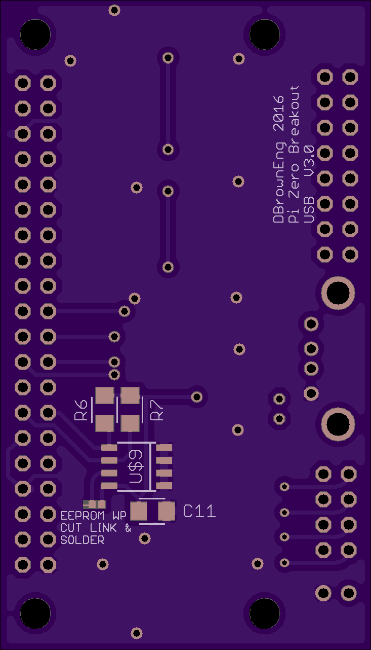
sudo ./eepflash.sh -w -f=blank.eep -t=24c32Answer yes and wait. The write protect is disabled by the small ground trace and once programmed can be cut and the write protect soldered closed.
To verify if everything went well, you can use this command to check EEPROM content. Caution: it will only work after you use the eepflash command, which does some modprobes.sudo hexdump /sys/class/i2c-adapter/i2c-0/0-0050/eepromIf everything is okay, you'll only see zeros.
Then, you can upload your own myhat.eep.sudo ./eepflash.sh -w -f=myhat.eep -t=24c32And again, verify it after uploading :
sudo hexdump /sys/class/i2c-adapter/i2c-0/0-0050/eepromIf the contents match, you can reboot your Raspberry Pi.
To check if your HAT is recognised, just go to /proc/device-tree/. If you see a hat directory, you are a winner:)cd /proc/device-tree/hat/ more vendor more product -
0.1" header version
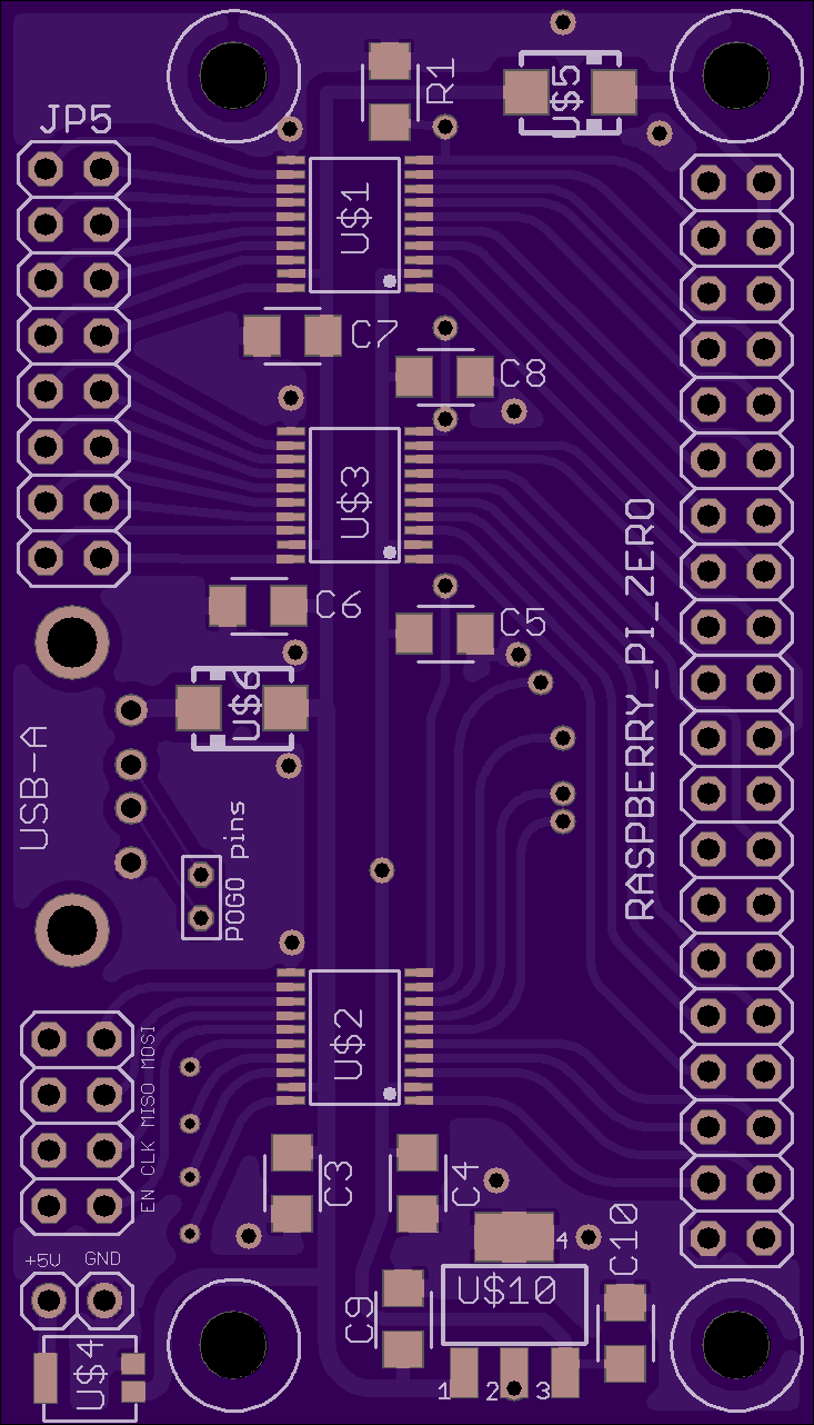
06/24/2016 at 16:18 • 0 commentsI've re-jigged the board to suit 0.1" header pins, this should make it more useful for a variety of projects. Files and schematic will be added to the files section.
![]()
![]()
-
Version v3.0
05/02/2016 at 13:43 • 0 commentsI've uploaded version v3.0 of the board which has the headers moved to prevent clash with the micro USB connector on the Pi. I have also added a PolyZen over voltage protection diode to the 5V inlet to add a degree of over voltage protection.
Before I killed the Pi, the wifi adaptor plugged directly into the v2.0 board was working happily through the pogo pin connection to the header pads on the Pi.
-
v2.0 board
05/02/2016 at 00:11 • 0 commentswell I've recieved the v2 boards from OSH and everything looks good. I've noticed one irritating issue, which is the micro USB ports on the zero stick out slightly, and clash with one of my headers, but is fine if run as a 90deg header under the board.
The other issue was when I accidentally contacted my 5V converter against the shielding on a ribbon cable and fried (connected to 12V) the zero and I assume the level converters - oops. So I want to add some voltage protection in the form of a voltage protection diode.
So I will make some adjustments and upload the finalised version.
![]()
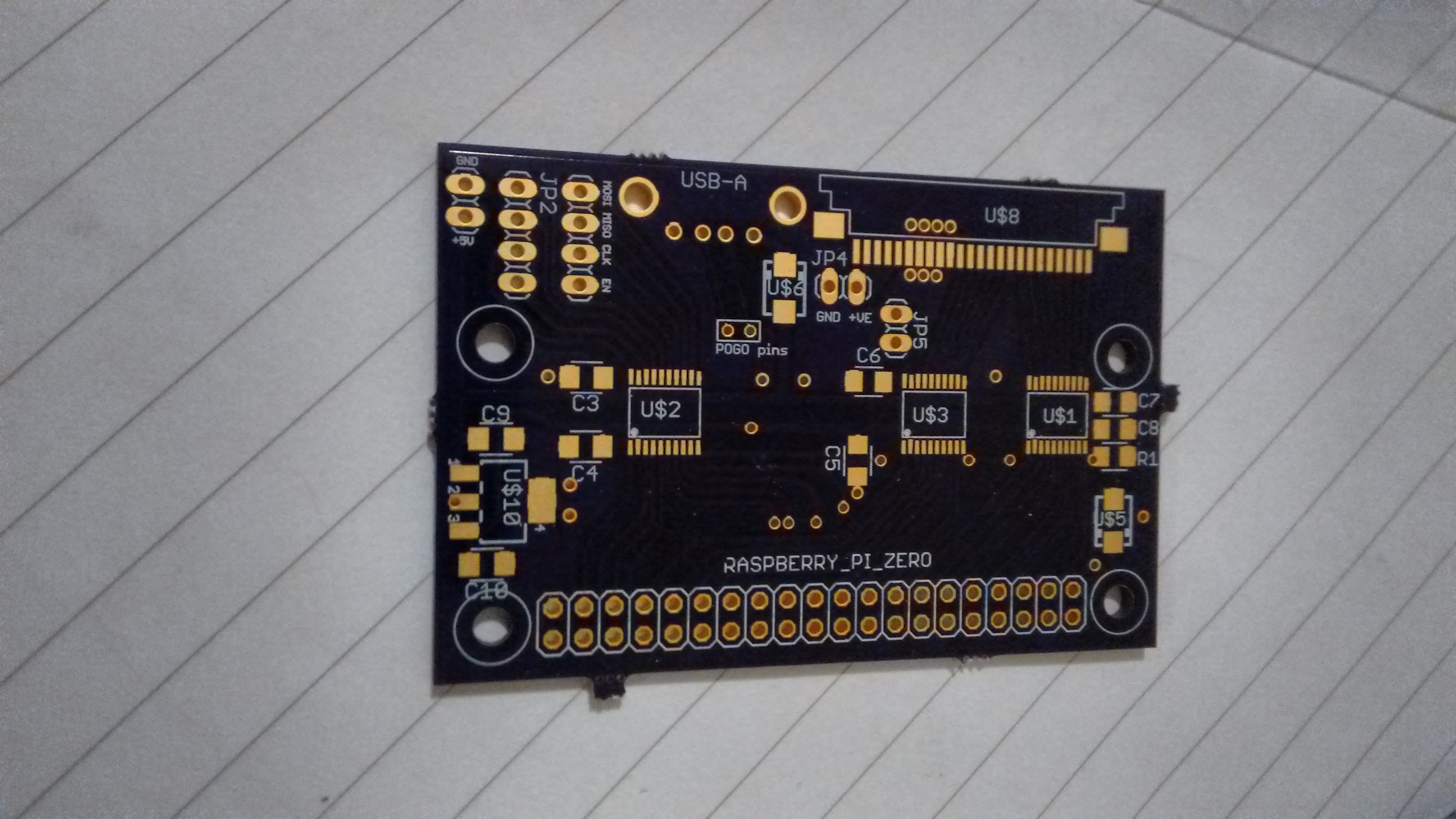
Bare board
![]()
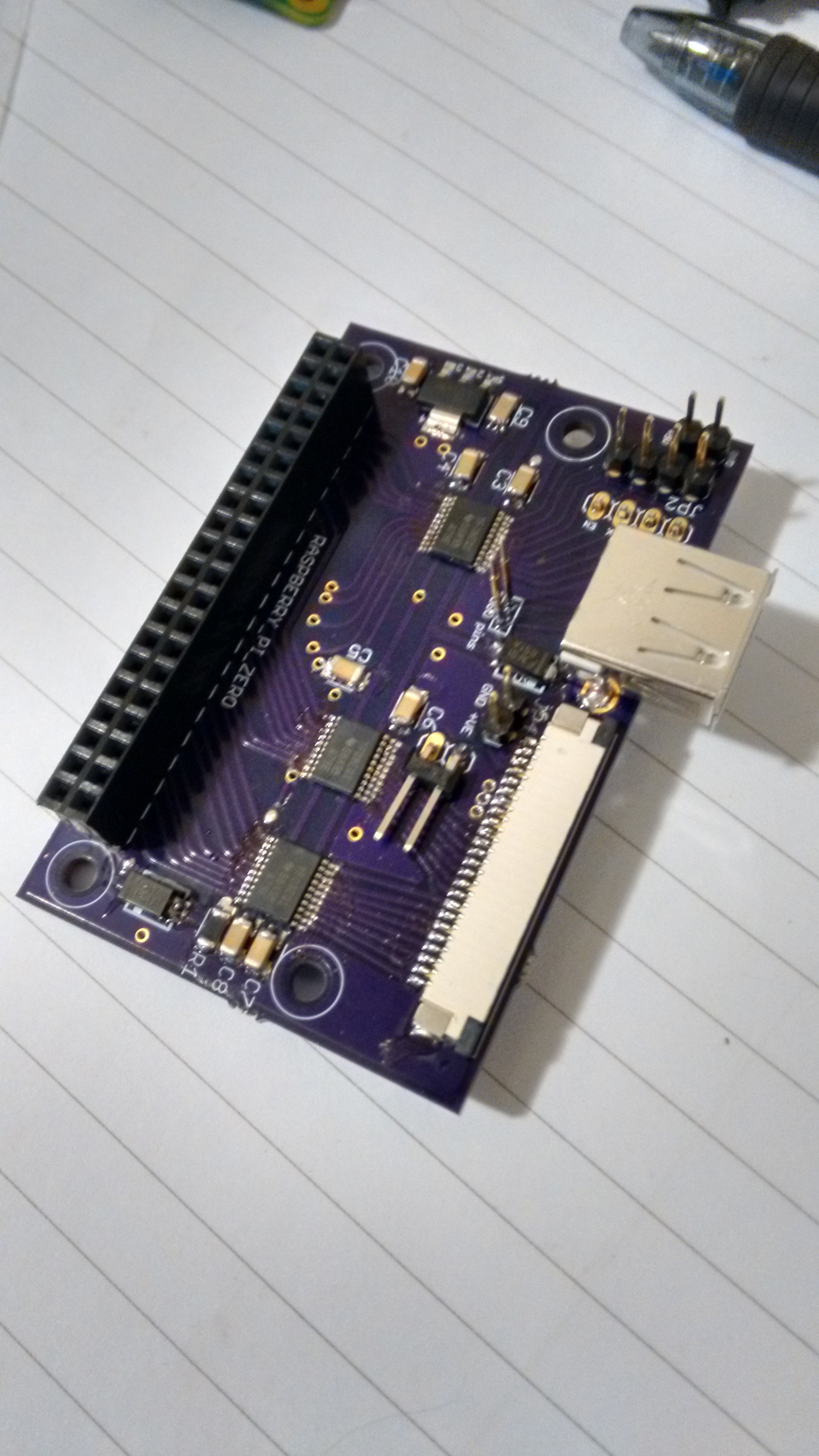
Populated board
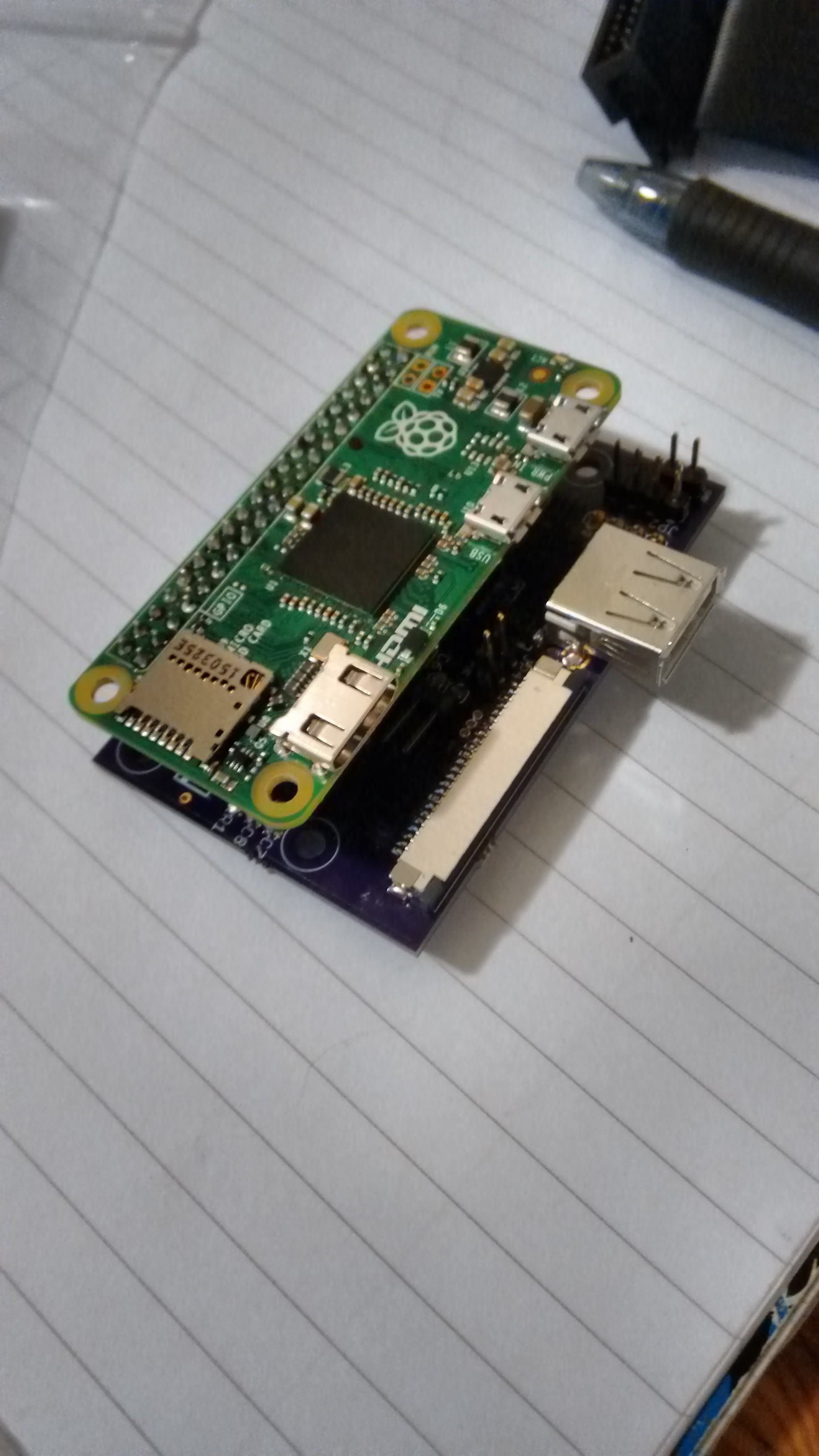
![]()
Board & Raspberry Pi Zero
Raspberry Pi Zero Breakout
A break out board for the Raspberry Pi Zero for use with 5v signalling, and featuring a full size USB-A socket