 body interaction team
-
1Step 1
Print out all forms.
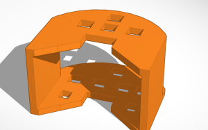
encasement:
![]() hanging:
hanging:![]()
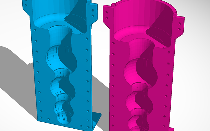
molding form:
![]()
-
2Step 2
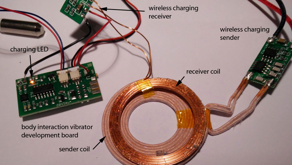
Connect the wireless charging module to the body interaction vibrator development board. The image shows how all components work together.
![]()
Now we show how-to connect wireless charging module and body interaction board.
B.1 You have to solder a wire connecting (-) on the wireless charging module and GND on the body interaction board.
![]()
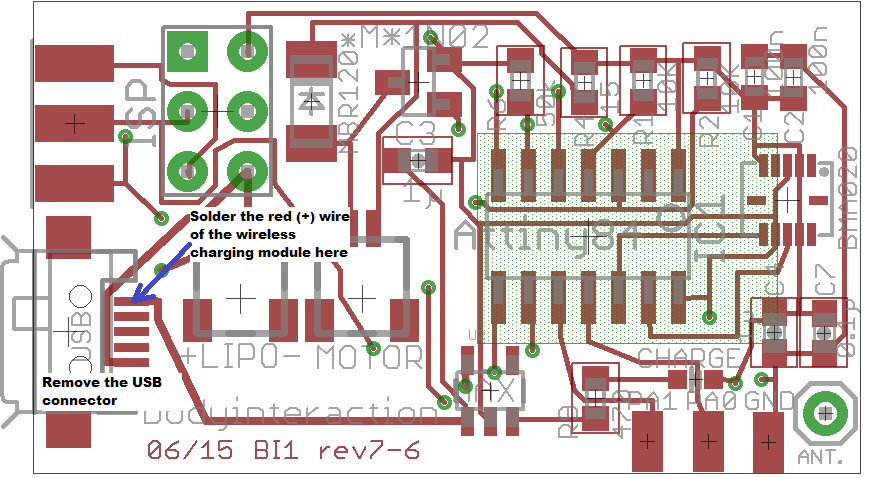
B.2 Now comes the tricky part. You have to connect (+) from the charging module with the body interaction board. Solder a wire at (+) of the charging module. But where do you solder the wire on the body interaction board? Unfortunately the wireless charging option was not taken into consideration during the development of the board. So there is no appropriate connection on the board.
The best solution is to unsolder the USB connector and connect to + of the USB connection. The easiest way to unsolder the surface mounted USB connector is done with a hot air soldering station. Alternatively you can solder the wire directly to the MAX1555 module – this solution is presented here. In any case: Be careful not to break the tiny pads connecting pcb and USB connector.
-
3Step 3
Now construct the charging station:
Simple way: Connect the sender module with a 5V power supply. You can use a USB cable, dismantle the cable and connect the black and red wires. Go to step 4.
Build charging station: Go to step 13
-
4Step 4
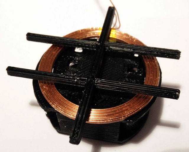
Place the receiver charging coil on top of the enclosure. The diameter of the top side is a bit larger than the diameter of the bottom side. Use some glue to fix the coil. Don’t fix the mounting now. It is easier to do it later (step 6).
![]()
-
5Step 5
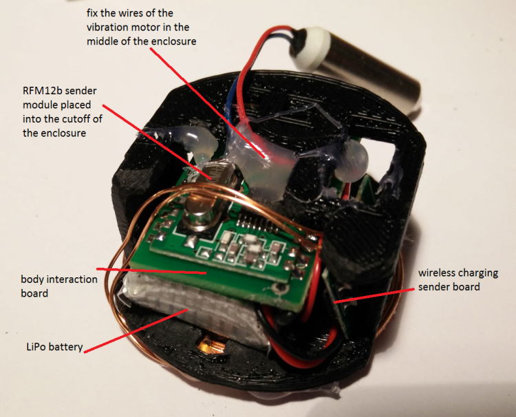
Put the electronics into the enclosure: Begin with the body interaction board. The RFM12b module on teh back of the bodyinteraction board is quite large so place it at an outer position. Then insert carefully the LiPo battery. Don’t force it! The plugs for the battery and the motor could break. If you have done so insert the tiny wireless charging receiver board. At the end fix the wires of the vibration motor in the middle of the enclosure.
![]()
-
6Step 6
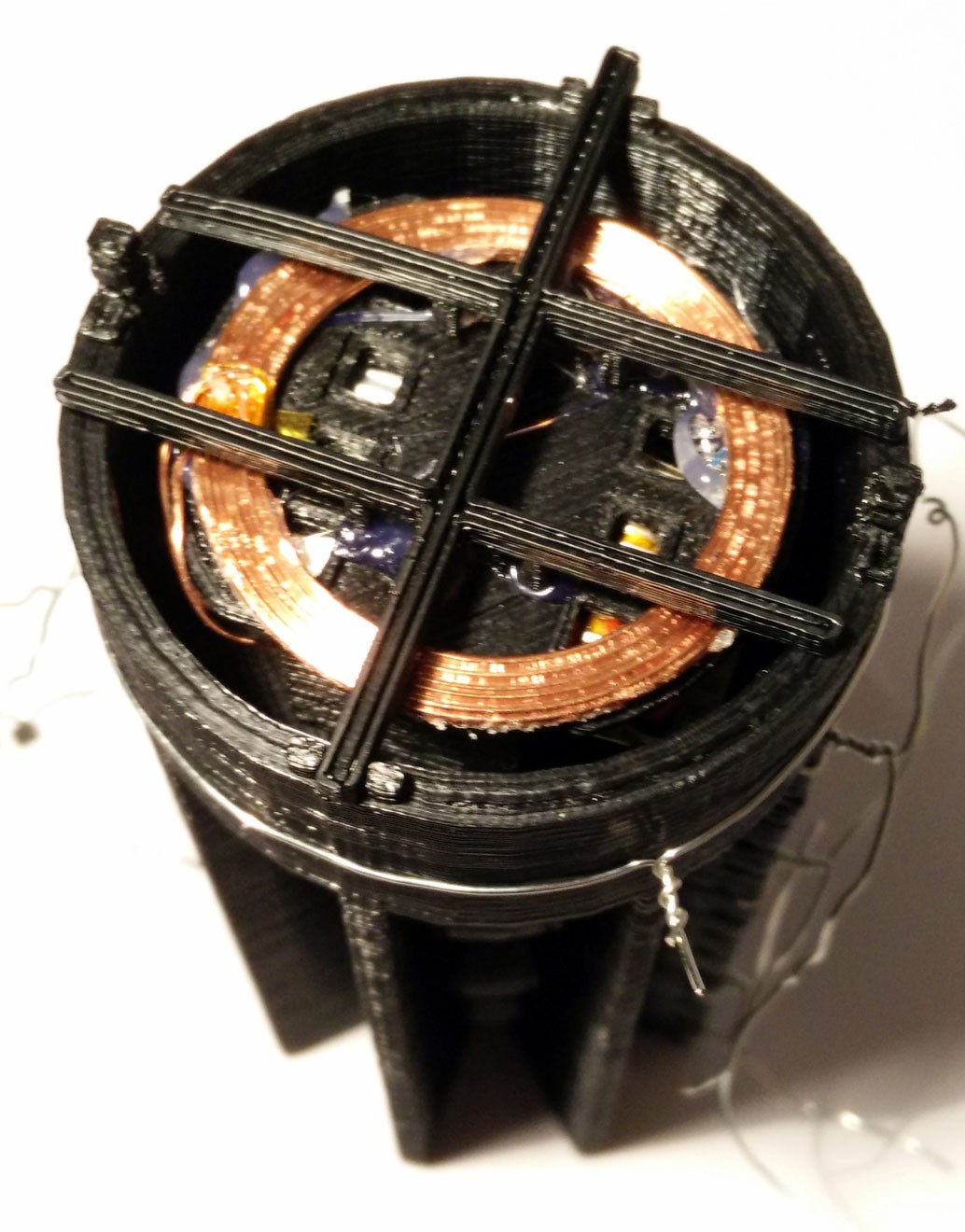
Connect the mounting with the enclosure. There are 2 holes provided where the mounting fits into the enclosure. Use someglue to stick together both parts.
![]() Alternative charging module:
Alternative charging module:![]()
-
7Step 7
Put together both parts of the molding form. Use tinkering wire to attach both parts tight together. Then insert the enclosure into the form. Check the wireless charging function. The yellow LED must be on when you place the charging coil over the receiver coil.
![]()
-
8Step 8
Now poor silicone into the molding. We use Shore A 45 silicone which is rather hard. The silicone has to dry for some hours or days. Read the instructions of your silicone provider.
![]()
-
9Step 9
When the silicone is hard, you can remove the tinkering wire. Then carefully remove the form.
![]()
-
10Step 10
Remove the overhanging silicone parts,
before
![]() after:
after:
in blue:![]()
![]()
Wireless Arduino-powered Vibrator
Building your own silicone molded vibrator. Use a 3d printer for printing the form. Drive the vibration motor with a Arduino board.
 hanging:

 Alternative charging module:
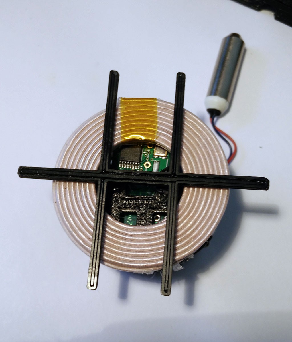
 after:
Discussions
Become a Hackaday.io Member
Create an account to leave a comment. Already have an account? Log In.