0%
0%
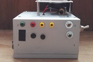
ATX power supply conversion for bench usage
I'm converting an Enermax EG465AX-VE(G) into a bench power supply for my hacks.
 Christoph
Become a Hackaday.io member
Already have an account? Log in.
Just one more thing
To make the experience fit your profile, pick a username and tell us what interests you.
Pick an awesome username
hackaday.io/
Your profile's URL: hackaday.io/username. Max 25 alphanumeric characters.
Pick a few interests
Projects that share your interests
People that share your interests
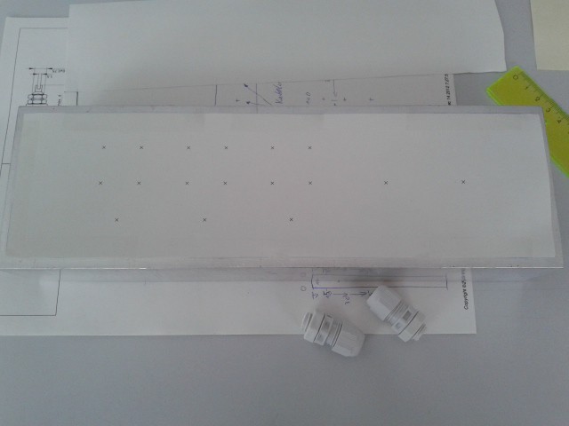 It's missing the marks for the switch and the LEDs, I added them later.
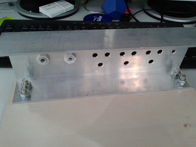 I used additional spring washers for the M8 screws.


 Orlando Zen
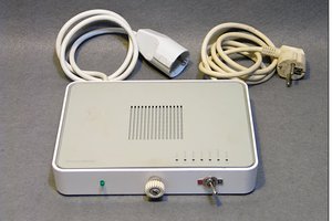
 carbono.silício
 ASHUMHRPROJECTS
 csdesign
hi christoph and thanks. i'm a total beginner with this, but have used atx psu's to power arduinos and motors in my sound installations for a couple of years now.
usually i only need to connect the green cable to a black ground and it works fine but i tried this on a new unit i just bought and it's runs for a fraction of a second then cuts out... is this where the minimum load comes in?
and do you need to add a minimum load on every output as in this project, or usually only on the 5vsb output?
also, if i am unable to get my hands on these power resistors (or even this doesn't work) do you have any other suggestions please?