Peter McCloud
-
Designing Custom Rotor Pulleys
11/07/2015 at 21:09 • 1 commentOne of the goals of the project is to use as much off-the-shelf hardware as possible. The prior rotor pulleys were standard pulleys and readily available. A few of the issues with the prior pulleys were that they were made of steel and required a separate steel bushing. While aluminum pulleys can be purchased, they have to be custom ordered.
How Timing Pulleys are Constructed
There are several examples across the Interwebs about how to build timing pulleys and in particular HTD pulleys. Building a single pulley or a small batch of pulleys can be done with machine tools. Below is a good example by DIYisFun building a small pulley from a block of material on a mill.
Another way is to use a fly cutter to create pulley stock from a block of material. Here is another video from DIYisFun showing how a fly cutter is used to create a timing pulley.
This method is a bit time consuming. A good compromise is to purchase the raw pulley stock and cut the pulleys from the stock. This will only require basic machine tool operations. Aluminum stock of different sizes and pitch can be readily purchased.
One last consideration is adding flanges to the pulleys. The flanges are required because the belts operate in a horizontal position. The flanges can also be readily purchased with the pulley stock, but there are several methods of attaching them. The prior pulleys appear to have flanges attached using a method called roll staking. Here is a video showing how roll staking is done.
The roll staking requires special equipment, so the options are either to use bolts to attach the flanges or use a punch to do conventional staking.
New Rotor Pulley Design
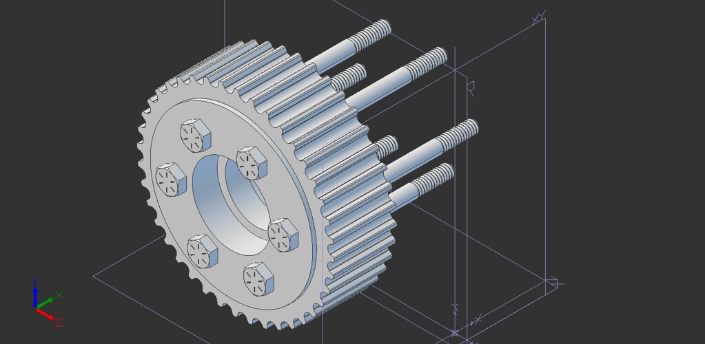
Making the rotor pulleys isn't as simple as lopping off a piece of pulley stock. The rotor pulley has to accommodate the flanges, the bearings and the rotor bolts. Below is the CAD design of the pulley with 6 fitted 1/4" diameter bolts, 4" long.
![]() Machining steps:
Machining steps:- Mount pulley stock
- Cut 1st shoulder to 1.77" radius 0.22" wide
- Cut off the length of pulley from the pulley stock (1.60" wide)
- Remount using 1st shoulder
- Cut second shoulder 1.77" radius 0.15" wide
- Bore center hole
- Bore 1st bearing pocket
- Face Surface
- Remount using second shoulder
- Bore 2nd bearing pocket
- Face Surface
- Drill bolt holes
Any feedback on the pulley design or tips on doing the actual machining would be appreciated.
Benefits
The new pulleys should weigh about 1.3 lbs and the previous pulleys weighed 2.6 lbs so the total weight reduction for the four rotor pulleys will be at least 5 lbs. There will likely be further weight reductions since the bushings are being eliminated as well. Finally, having the six fitted bolts vs. the three fully threaded bolts will solve the rotor bolt issues.
-
Latest Tests Completed
11/06/2015 at 23:18 • 0 commentsThe latest testing with the new rotors has been completed. However, Goliath still isn't flying. Most of the testing was troubleshooting Goliath after reassembly. It seems that a few tests are always required to get everything setup up correctly when Goliath has been reassembled. Below are the videos of the latest testing, then a description of what changes were made and what's next.
Tests 22 & 23
Mostly troubleshooting Goliath after reassembly, securing hardware and getting the belt tension correct. Increasing the throttle above idle has little effect.
Tests 24, 25 and 26
More of the same. Finally got the belt tension correct for test 26, but the propeller bolts fail toward the end of the test. The engine was still mostly unresponsive to throttle settings above idle.
Changes
New Rotors
A brand new set of propellers were manufactured since Test 21. The angle of attack at the tips was decreased to change the power vs. RPM curve to better match the engine. The new propellers should require less power at lower engine speeds, allowing the engine to rev up to higher RPMs. The new set of rotors is shown below.
![]()
Propeller Bolts
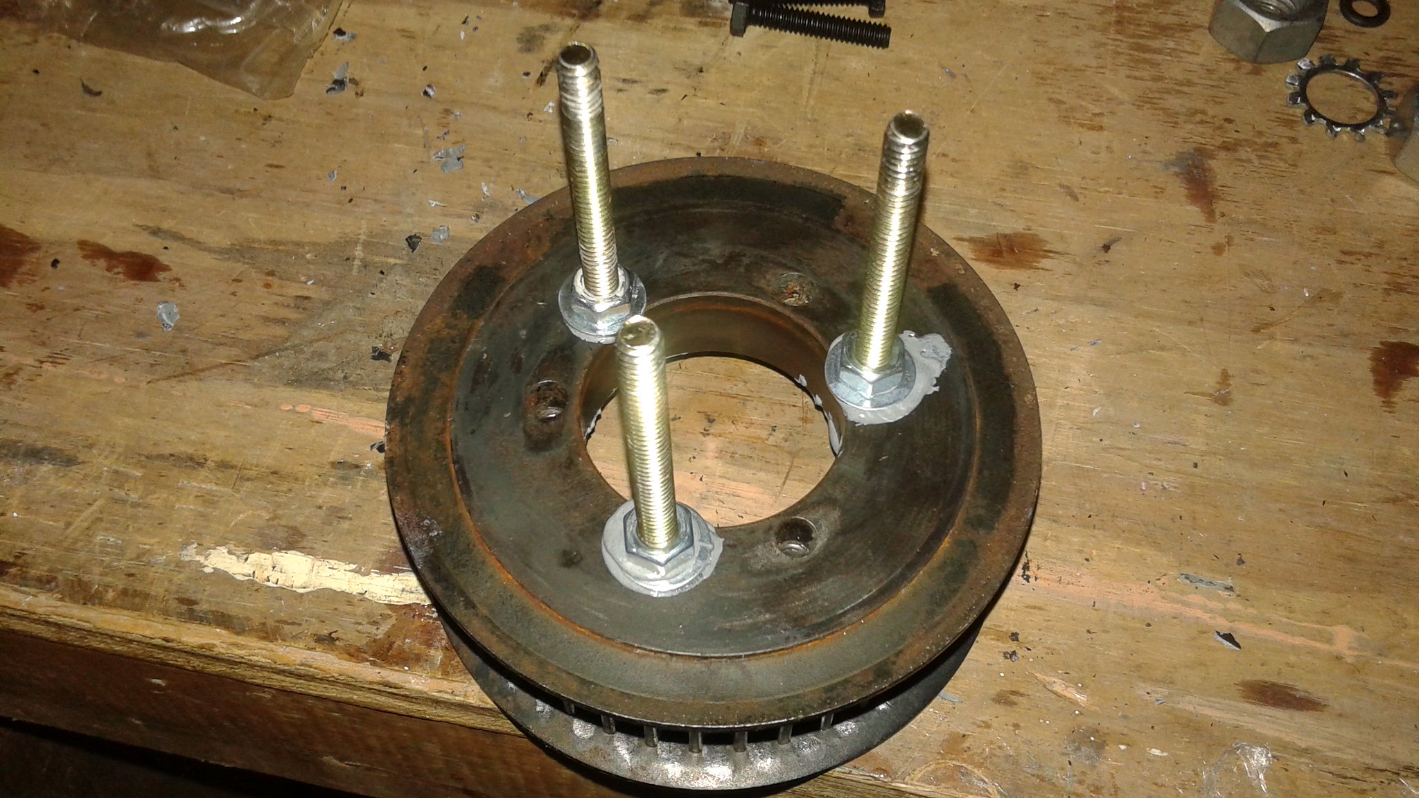
During prior tests the bolts attaching the rotors to the pulleys have broken on a few occasions (see prior project logs). The bolts are supposed to merely hold the bushing to the pulleys, but have been replaced with longer bolts that serve to also attach the rotors. This time around the original bolts were put back in and a new set of bolts were added to attach the rotors with. The purpose of doing this was to decouple the loads required to hold the bushing to the pulley together and the loads from the rotors. The new rotor bolts were epoxied with JB Weld into empty holes already present in the pulleys. Below is a picture of the bolts being epoxied in place. the nuts and washers are on the bolts to hold them in place.
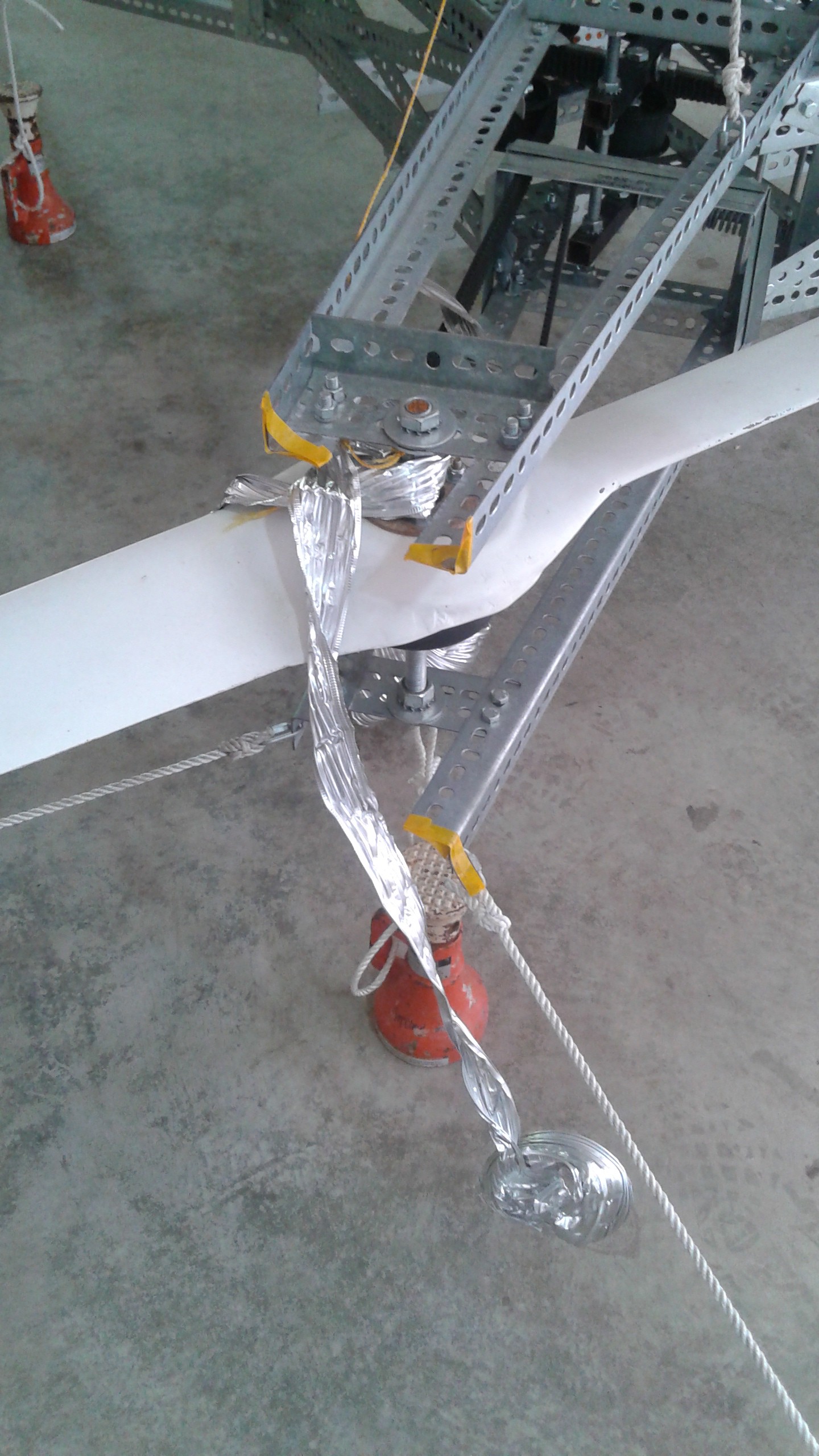
![]() Obviously this didn't work. Two of the bolts were broken off and one of the bolts was pulled out of the hole. It's difficult to tell exactly what failed first. I suspect that the bolt that got pulled out of the hole didn't have a strong bond and failed first. The load on the other bolts increased, subsequently causing them to fail. Of course it's possible that one of the other bolts broke first and then the rest failed.
Obviously this didn't work. Two of the bolts were broken off and one of the bolts was pulled out of the hole. It's difficult to tell exactly what failed first. I suspect that the bolt that got pulled out of the hole didn't have a strong bond and failed first. The load on the other bolts increased, subsequently causing them to fail. Of course it's possible that one of the other bolts broke first and then the rest failed.![]()
Choke Servo
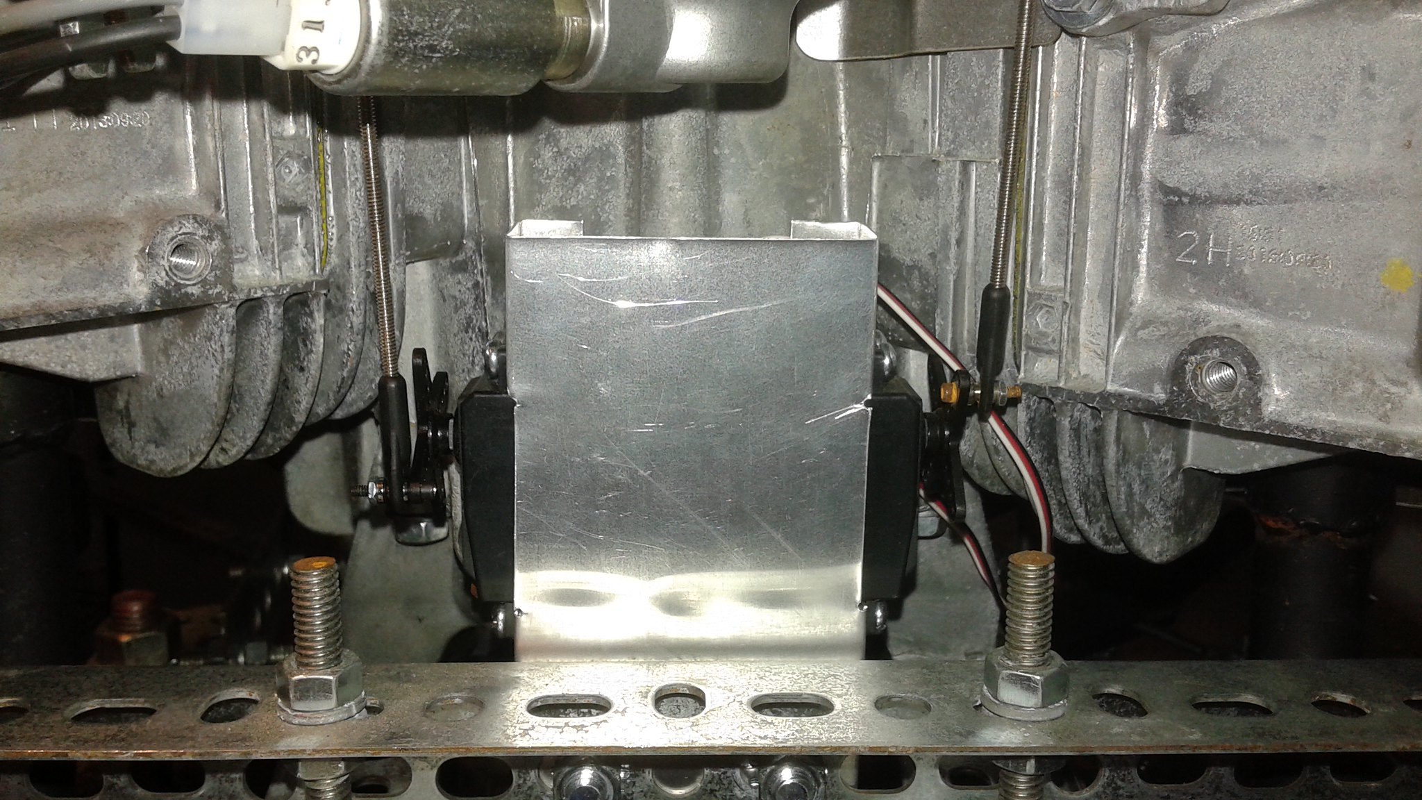
Before test 21, a second servo for the choke was added, but until a few weeks ago the linkage hadn't been connected. Now the linkage is connected to the choke lever. Below on the right is the throttle servo and on the left is the choke servo.
![]() Connecting the linkage was problematic because the air intake is in the way. Below is a photo with the upper ball link installed and the tight clearances around the linkage. On the right is the side of the carburetor and on the left side is the air intake.
Connecting the linkage was problematic because the air intake is in the way. Below is a photo with the upper ball link installed and the tight clearances around the linkage. On the right is the side of the carburetor and on the left side is the air intake.![]() In order to get the nut on the linkage, a special wrench was required:
In order to get the nut on the linkage, a special wrench was required:![]() Having the choke servo made starting the engine much easier. Previously starting the engine involved closing the choke, running the engine for 30 to 60 seconds to warm it up, shutting down, then setting the choke to open and then performing the actual test.
Having the choke servo made starting the engine much easier. Previously starting the engine involved closing the choke, running the engine for 30 to 60 seconds to warm it up, shutting down, then setting the choke to open and then performing the actual test.What's Next
Fixing the rotor bolt issue is the biggest item that needs to be resolved. So far the measures attempted accommodated the existing pulleys. It had already been apparent that custom rotor pulleys made out of aluminium would be needed to decrease the weight. Making these new pulleys is now on top of the list. Designing the pulleys is still in work, but the new pulleys will likely have six bolts instead of three. The new bolts will also be fitted bolts instead of fully threaded bolts (as @mechanicalsquid has discussed). There will be a project log in the future detailing the custom pulley design.
More data is also needed to figure out the engine issues, particularly engine RPM. There is already a hall effect sensor installed to sense the magnet built into the flywheel. It just needs to be utilized now to sense the engine RPM.
-
Getting Closer to the Next Test
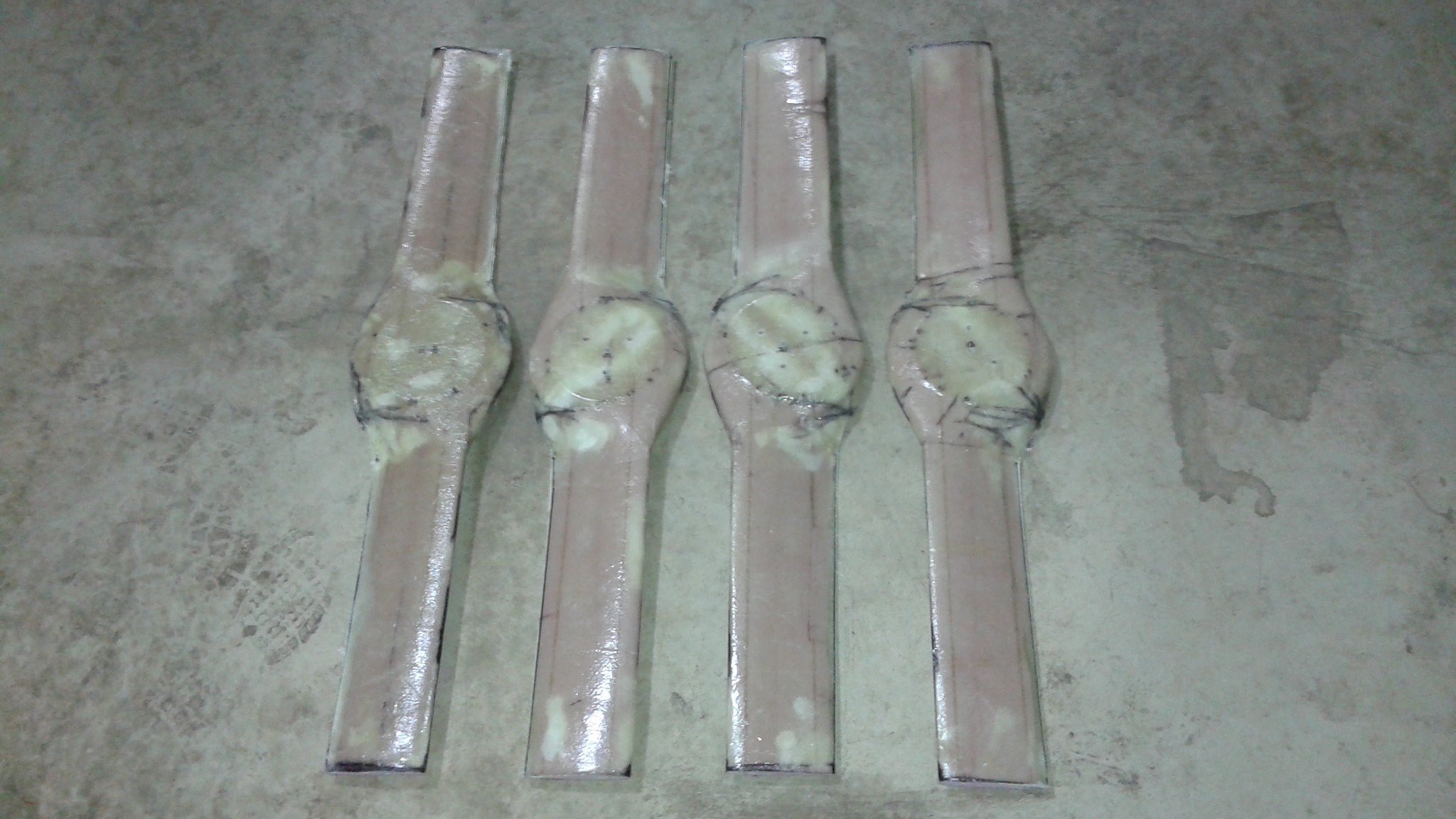
10/08/2015 at 21:31 • 4 commentsWhen I last wrote, I was in the middle of making a new set of rotors for Goliath to address the RPM/power mismatch between the rotors and the engine. After a lot of work, the last of the new rotors was pulled out of the vacuum bag two days ago. Here is a shot of the four new propellers after having the excess material trimmed off.
![]()
All that remains now is to cut out the center hole, sand the rotors smooth and apply a final coat of paint.
One other item that has to be addressed before the next test is to swap out the rotor mounting bolts again. Previously the 1/4" grade 5 bolts were replaced with 1/4" grade 8 bolts. They seemed to work, but the other day it was found that one of the new bolts had broken in the same manner as the old bolts. If you haven't seen it, this is what happened previously:
![]()
The 1/4" bolts will now be replaced with 3/8" bolts. This will require drilling larger holes through the pulleys and the bushing.
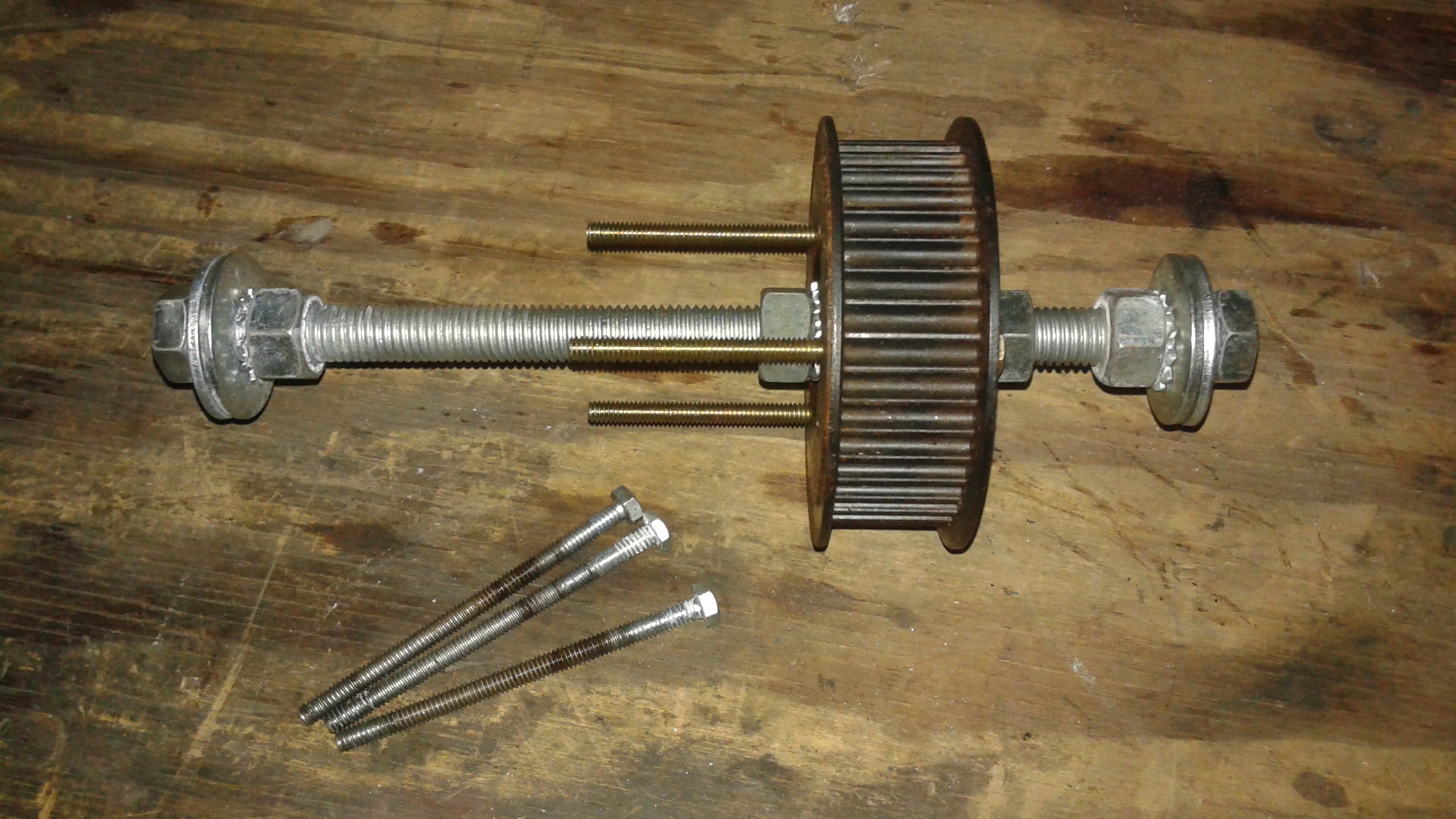
In the future, the plan is to make a custom pulley. The custom pulley will be aluminum and will be a single piece instead of the pulley/bushing combination. To prepare for this, a 3 in 1 Smithy (Mill, Lathe, Drill Press) was obtained to make the custom pulleys and this week, the aluminum pulley stock arrived.
![]() The pulley stock is 10" long so I can make 7 or 8 30mm wide pulleys with it. It's been a long time since I've worked on a lathe, and I haven't made a pulley before, so we'll see how it goes.
The pulley stock is 10" long so I can make 7 or 8 30mm wide pulleys with it. It's been a long time since I've worked on a lathe, and I haven't made a pulley before, so we'll see how it goes.With some luck, the next post will be a summary after the next test is completed.
-
Manufacturing Issues
08/19/2015 at 00:56 • 1 commentThe design of the new rotors for Goliath is complete. There's also been a lot of effort spent making a separate repository for the rotors. The goal is to provide everything a person would need to manufacture their own rotors from scratch using the process used for Goliath. Manufacturing of the rotors has started, but there has been some issues machining the new rotor cores.
To avoid any confusion, the numbering system for the cores started with original cores built for Goliath (Cores 1 through 4). Two were destroyed in the second test and were replaced with rotors 5 and 6.
For the 7th core, in addition to use the new tool paths, there was an attempt to optimize the cutting path and reduce the cut time. The optimization worked for one side, but ruined the leading edge on the other. It was decided at that point to hold off the optimization until after enough cores were completed.
The 8th core came out acceptable with no issues. The 9th core had a bad trailing edge. It appears that the bottom cuts were performed with the z-axis slightly too low and too much material was cut off the rotor and the trailing edge broke. To help ensure the Z-axis was aligned properly for the following propellers the spoil board was re-machined to ensure it was level.
The next core, the 10th was completed without issue and was likely the cleanest of the cores that have been made. The 11th core, was the first of the new clockwise cores since cores 8 and 10 were counter-clockwise rotors. The tool path was loaded and the router was left to rough out the top of the rotor. This was the result after returning the the router:
No idea what happened.![]()
Making additional rotors is on hold all the birch plywood is used up. Meanwhile the new tool paths will be tested out on a purely foam blanks to avoid wasting more birch. Work can also start on fiberglassing cores 8 and 10. There's still a lot of work left to do, so it'll be several weeks until all of the new rotors are completed.
-
35 lbs short
07/10/2015 at 19:21 • 3 commentsThrust measurement and weight reduction has been the focus of the work on Goliath over the last few weeks. Prior to the last test, Goliath weighed 238 lbs, about 40 lbs more than the target weight when the project started. With the vehicle design still in flux it's not time to move away from the slotted angle yet, but there were a few areas that could provide some potential weight reduction.
Bolts and Washers
When Goliath being assembled for the first time, the final design was somewhat nebulous. To make things easier, the same sized bolts where used for the frame assembly. Most of the bolts don't need to be the full length, so wherever possible, the original 3/4" long bolts have been replaced with 1/2" long bolts. The size difference is shown below. About 75 of these bolts have been changed out for smaller bolts
![]()
While the bolts were being swapped out, the traditional lock washers where replace with external toothed lock washers. The primary reason for replacing the washers is that the traditional lock washers aren't very vibration resistant and every test would see at least one or two come loose. A bonus to replacing the washers is that the external tooth washers are lighter than the traditional lock washers. The picture above also shows the external toothed and traditional lock washers.
Cross Beams and Side Beams
The side and cross beams previously used the wide slotted angle. It was felt that they could be swapped out for the narrow slotted angle with a minimal reduction in stiffness. Below on the right is the wide cross beam and on the left is the narrow cross beam replacement installed.
![]()
Cross Members
The cross members were another area improved. Previously the two cross members on each side of Goliath spanned the whole length of the side and angle wasn't ideal for stiffness. Each of the cross members where removed and trimmed into two smaller pieces, with a little bit of excess. These pieces where then used to form two smaller crosses on each side. Below is a shot of the side beams and cross members being reconfigured on one side of the vehicle.
![]()
After completing the structure modifications, the end result is that Goliath looks a bit leaner, and the weight was reduced by 5 lbs to a total weight of 233 lbs. The slotted angle structure is probably as lean as it's going to get.
![]()
Propeller Axles
Another issue that needed to be addressed was the axles for the two propellers powered by the double sided belt. After inspecting the vehicle it was found that the axles were slightly deformed (see picture below). The double sided belt needs additional tension, probably because of the extra length and the difference in the angles. Eventually the all-thread axles will be replaced with thicker axles, but for now an easy fix was to replace the 5/8" zinc plated all thread rod with 5/8" stainless all thread rod. The stainless has a higher strength and has more resistance to being deformed.
![]()
Thrust Measurement
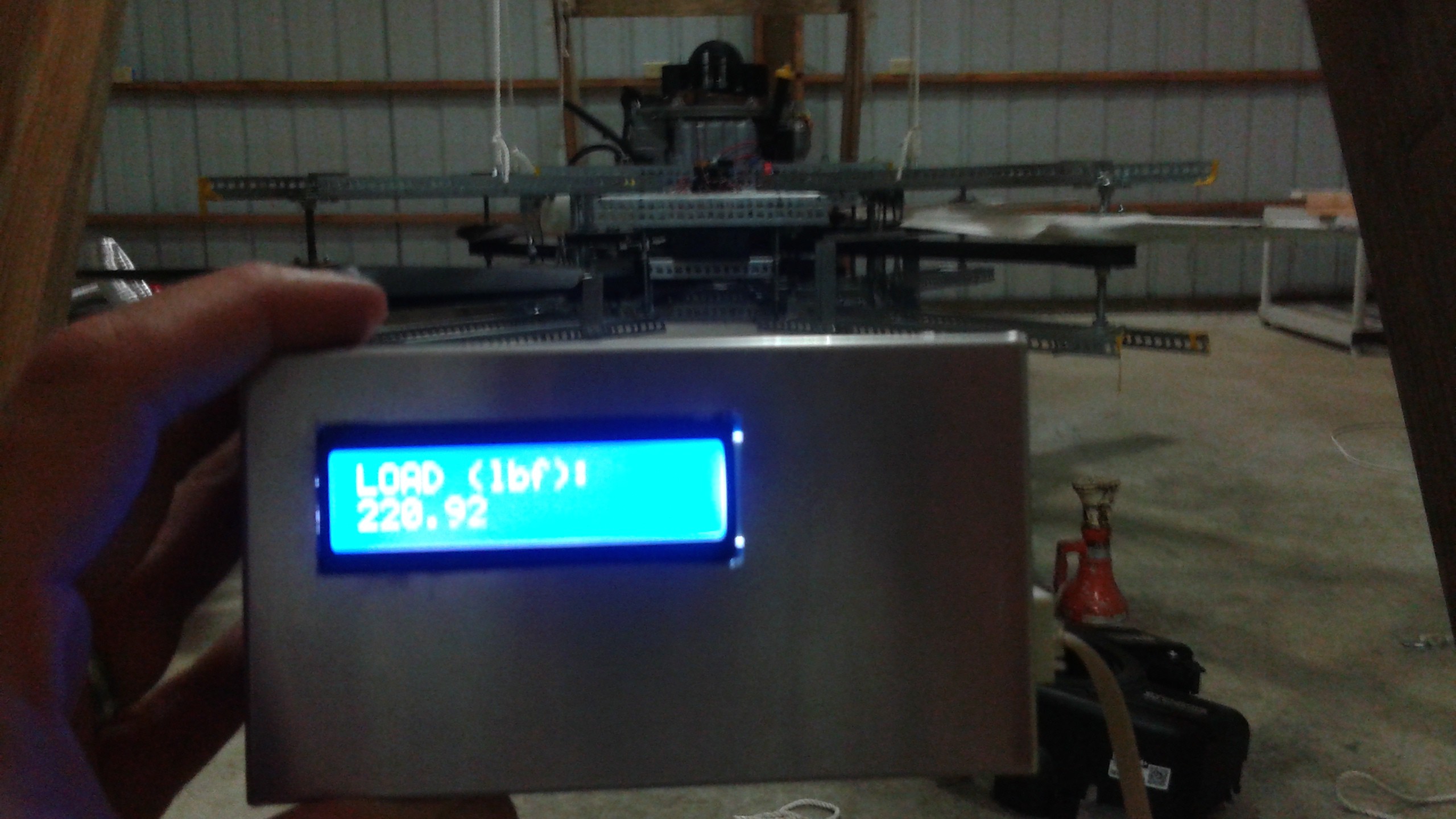
The thrust measurement portion of the # Drone Test Stand has been completed. You can read the details there, but the test stand has been setup to measure the thrust while Goliath is running. Below is a picture of the remote display with Goliath in the background.
![]()
In the above picture the reading says 220.92 lbs. This was because some of the hardware had been removed from Goliath. Note that there is no data logging capabilities built it. The measurements are being recorded visually for now.
Testing
Three more tests have been conducted since the last posted test. There hasn't been time to compile the video yet, it'll probably get posted over the weekend.
Test 22 tested the latest changes in the frame. The test went smoothly and Goliath was brought up to full speed without the ignition switch coming loose. There was no flexing in the frame visually, so the new design appears to be working.
Test 23 attempted to get full thrust measurement data. However the double sided belt tensioner was not performing satisfactorily and the engine speed was limited to 25%. The thrust measured at 25% throttle was approximately 70 lbs.
Test 24 was performed after a redesign of the tensioner, the details of which will be posted in a later project log. This time the tensioner worked and Goliath was able to get to 100% throttle. The recorded load at full throttle was 31 lbs, but the readings were 11% low at the start of the run. Accounting for this offset the actual load is closer to 35 lbs at full throttle and the total thrust was (232 lbs - 35 lbs) = 197 lbs.
While there isn't any corresponding RPM data. The data corroborates what the latest analysis suggested.
As @Smerfj pointed out in a comment on my last point. The issue is really an RPM mismatch. Here's a quote from his comment:
"If you need all 30 Hp to lift, the engine must run at 3600 rpm and the current prop must run at 2700 rpm. So you need a pulley that allows the motor to run at a speed ratio of 3600:2700 or 4:3."
[Edit: @Smerfj noted I made an error here. The ratio he was referring to above is the speed ratio and the pulley ratio is the inverse. This means that the propeller pulleys need to be larger than the main pulleys to get them to the right speed]
The current pulley ratio is 10:11, to change the ratio either the propeller pulleys need to be made larger or the main pulley needs to be smaller. All of the pulleys are as small as they can be without risking the belts skipping teeth. Larger propeller pulleys could be used and it would provide more area for torque transfer, but bigger means heavier. Larger pulleys would also require changes to the entire belt layout. Redesigning the propellers requires some work, but no other reconfiguration would be required.
The next step will be completing a new propeller design and then making a new set of propellers.
-
The Likely Suspect...
06/26/2015 at 19:08 • 6 commentsThe last few tests have shown that under full power Goliath was unable to produce enough thrust to lift itself. Analysis shows that Goliath should have sufficient power to lift itself, but it's difficult to say why Goliath is not hovering without additional data on the actual thrust and engine power being produced. The electronics for measuring the thrust produced is almost complete. Measuring the engine power requires measuring the engine RPM and a hall effect sensor is being installed that will be triggered by the magnet on the flywheel.
Meanwhile the design analysis has been revisited again to make sure there wasn't something's that been missed. The power required calculations were shown to be sound, so a closer look was at the propeller design was next.
Originally when designing the shape of the propellers, analysis was performed using simplified blade element theory. This consisted of some code borrowed from a Matlab code that I got from a University of Cambridge website. An attempt to make a spreadsheet out of this was unsatisfactory and Prop Designer was tried instead. Aircraft propellers and helicopter rotors work on the same principle, but operate in different regimes. Since the hover condition (static thrust) was the design condition for Goliath, Prop Designer gave an answer, but the software warned it may not be a good answer. With the deadline for the 2014 Hackaday Prize looming, it was decided to push forward and design the propeller with an angle of attack at the maximum L/D of the airfoil to get an efficient design.
Taking a closer look at the propeller design required having a more accurate analysis. This time a python code was written to analyze the design and the issues encountered previously were resolved. While the new python code is giving the best results for the propeller design so far, it still needs to be validated with data. However if it is right, then the new analysis shows a reason why Goliath isn't flying and more importantly how I can change the design to get Goliath flying.
Below is a plot showing the predicted power curves for different propeller designs using the new code.
![]()
The current design has a angle varying from 20 degrees at the root to 12 degrees at the tip. The problem with the design could be that it produces too much thrust at lower RPMs. The predicted power is too much for the engine to get above 2400 RPM, limiting the power to 21 Hp. The predicted thrust is at this condition is 220 lbs. Goliath weighed 238 lbs when last tested, so this could be why Goliath isn't flying.
If this is indeed the case, then the fix is to lower the tip angle. The plot above shows 3 additional designs where the tip angle is decreased in increments of 2 degrees. The last design in the list has a tip angle of six degrees and looks to be the most promising. This design could allow the engine to run up to 3300 RPM generating 27 Hp and the predicted total thrust is 290 lbs which should provide more than sufficient thrust.
The next test will provide thrust data and possibly engine RPM data. This will help validate the software and provide a good path forward to get Goliath flying.
-
Back up and Running
06/13/2015 at 19:14 • 2 commentsGoliath has now been completely reassembled and is running again. It took awhile to double check everything and get the tension just right on the belts. Below is the video showing Goliath being tested after reassembly.
Obviously, the ducting didn't work well. I had assembled the ducting using screw clamps at the joints. In hindsight, I should have used sheet metal screws, in addition to the screw clamps, to keep it from vibrating loose. I had protected against the possibility of the loose ends falling down, but didn't think about the joints. When the ducting failed during the test, the vehicle was vibrating more than usual because the tension on the belts wasn't quite right. That was later fixed, so if I decide to use the ducting again, the vibrations shouldn't be as bad. Goliath didn't suffer any damage because the aluminum ducting is pretty insubstantial.
![]()
The second run was good, with the exception of the ignition connector coming loose after the engine came up to full speed (and I need to move my Styrofoam sheet stock somewhere else).
For those who haven't read about the ignition system previously, here's a quick refresher. The engine has two ignition coils, one for each cylinder. The coils don't require a power source and are triggered as the engine rotates. To start the engine, the ground connection to the coils is opened and then the starter is used to start up the motor. To shut off the engine, the connection is closed again.
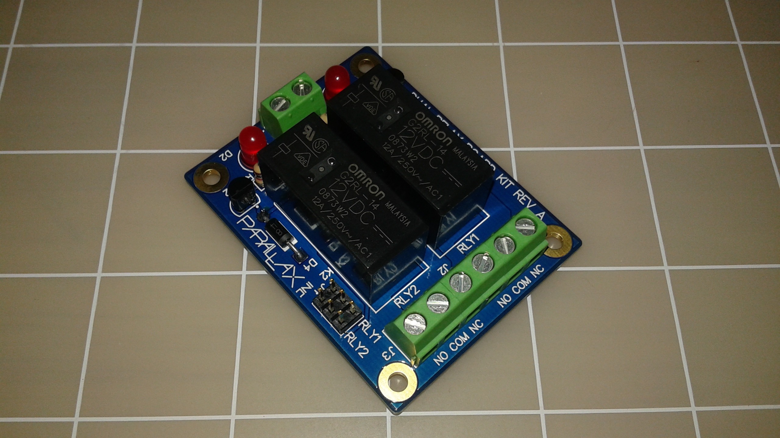
On Goliath, relays are used to operate the starter and ignition and the relays are setup for the ignition and starter to go to a fail-safe condition if they lose power or signal. During the full throttle test, the signal wire coming from the remote switch vibrated loose and the relay closed, grounding the coils and shutting off the engine. On the bright side, I know the fail-safe works, I just need better connections. Below is a picture I'd posted previously of the Parallax relay board being used on Goliath.
The relay signals come through the standard headers next to the parallax logo, labeled RLY1 & RLY2, connected with Futaba style servo connectors. The only thing holding the connectors to the headers is the contact friction on the pins themselves. Eventually, something more vibration-resistant, like the Hirose DF13 connectors that the Pixhawk uses, will be needed.![]()
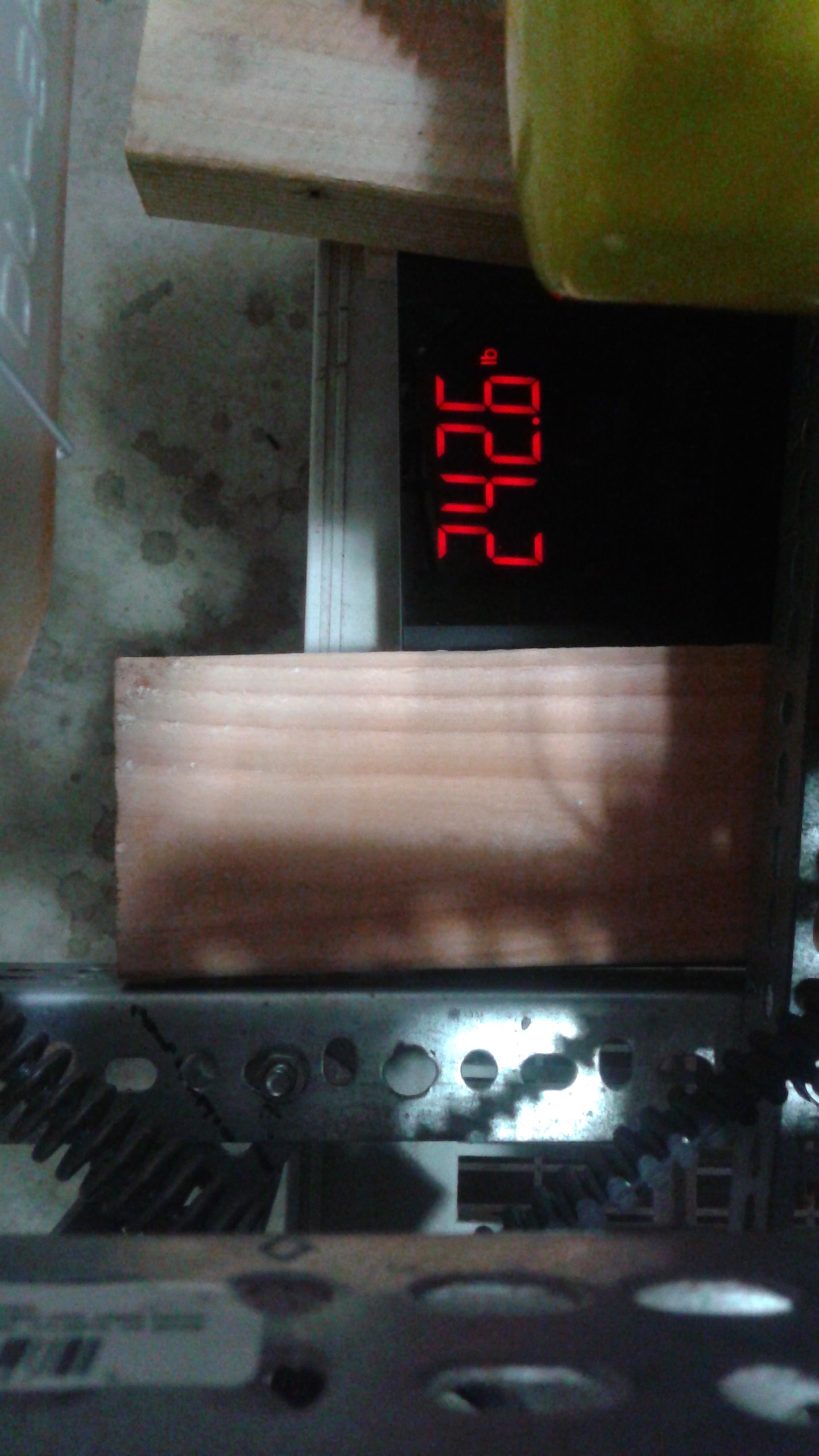
This was also the first test where I had good weight measurement immediately prior to the test. A bathroom scale was used to take the measurement. First, some wood blocks were placed on the scale to distribute the weight evenly and then Goliath was placed on top of the blocks. Here is a picture of the scale with wood blocks supporting the vehicle.
Subtracting out the weight of the blocks, Goliath weighed 238 lbs at the start of the test. This is higher than was expected as an empty vehicle weight of 200 lbs is desired, but Goliath weighs less than the theoretical total thrust of 255 lbs. It is evident that Goliath is putting out less than 238 lbs of thrust. The thrust measurement electronics will be finished up soon, which will give a better idea of the total thrust. The fix is likely going to be re-designing the propellers to get additionally thrust, but additional data is required before starting that effort.![]()
Efforts will continue to determine where weight can be eliminated without compromising the stiffness of the frame. Once the configuration is nailed down a bit more, a Mark II version with a lighter frame will be built, but for now, the design flexibility that the slotted angle provides is necessary. During initial testing, the frame tended to flex while the engine was running, particularly at startup (see Test 2 video below).
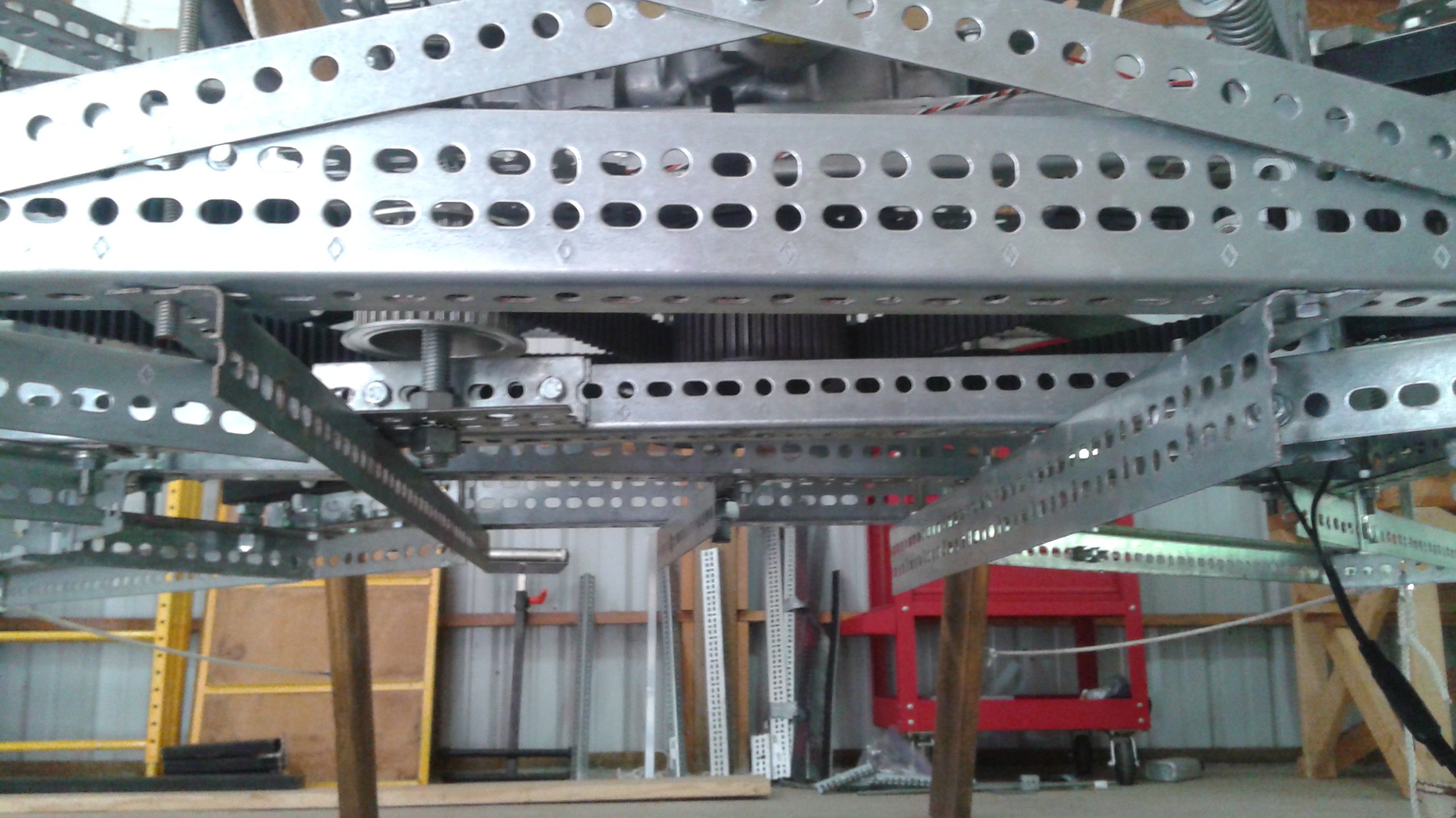
Later cross members and some all thread running vertically to stiffen the frame were added. It's sufficiently stiff now, but efforts have already been started to make the prototype lighter while maintaining the stiffness. Below is a shot of removing one side of the vehicle and replacing the wide side beams with narrow side beams and reorienting the cross members.
![]()
The new structure configuration will be tested soon and hopefully the thrust electronics will be completed shortly thereafter. Watch for more test videos in the near future!
-
Settling into the new place
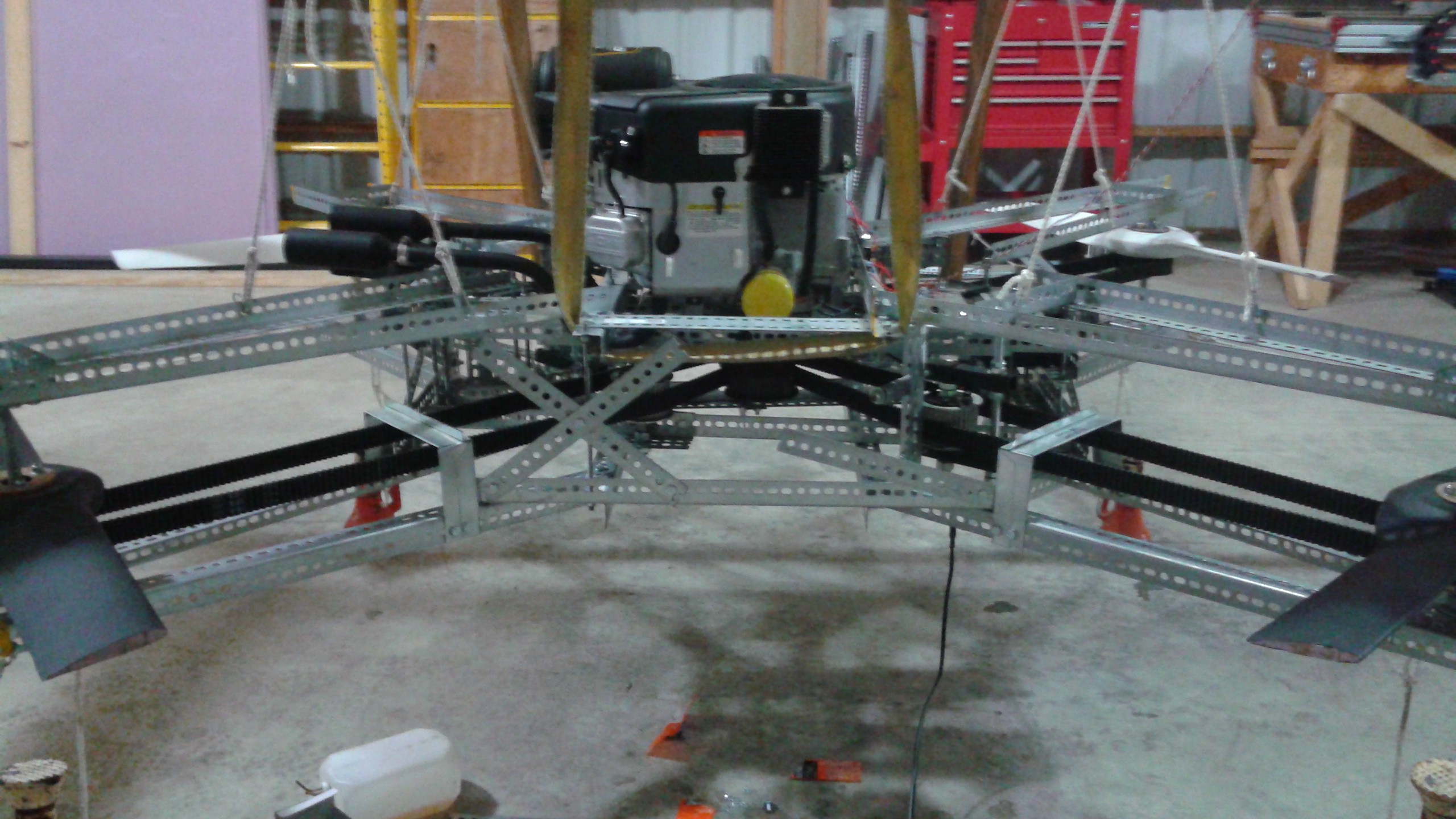
05/20/2015 at 03:14 • 1 commentI've been busy for the last month getting settled into the new house and getting Goliath unpacked. I had been hoping to transport Goliath in one piece (minus the oil and gas), but after the movers arrived and saw everything that was going to be packed, it became clear that wasn't going to happen. So I had to disassemble Goliath in addition to the test stand. Here's a shot of Goliath before being packed up on the moving truck.
![]()
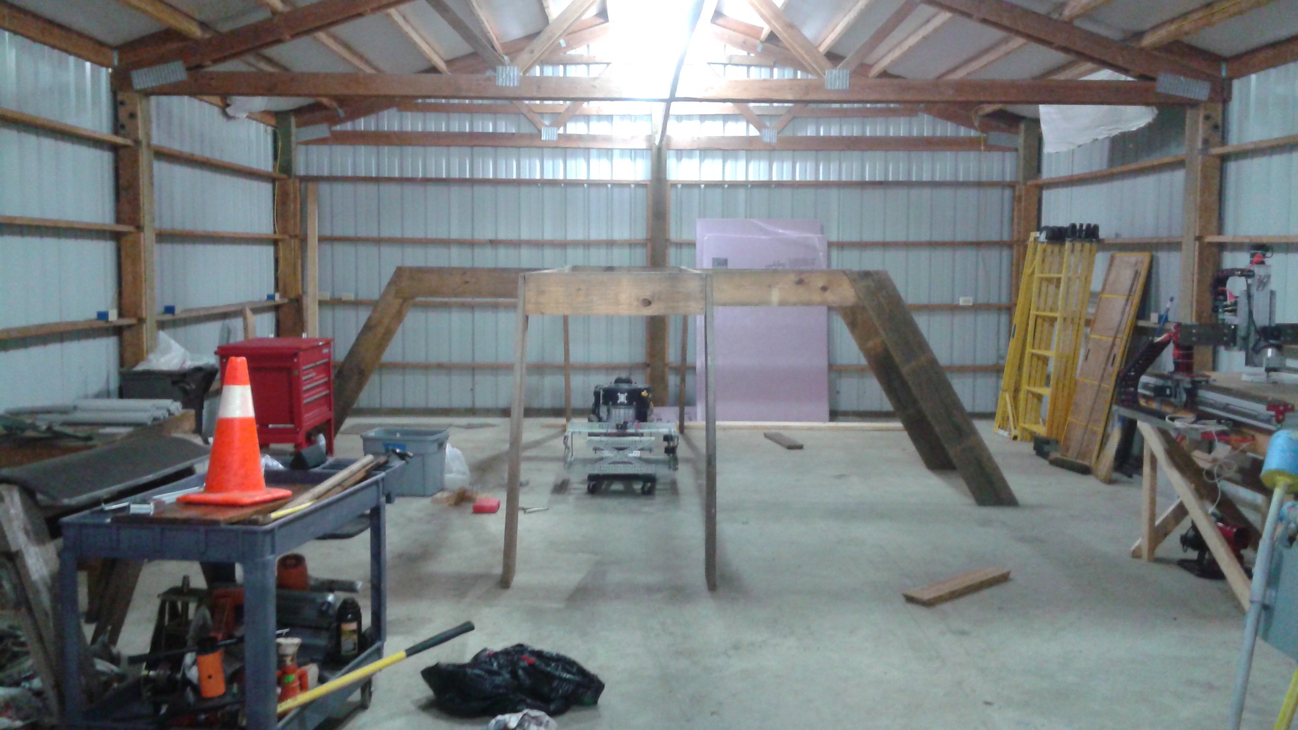
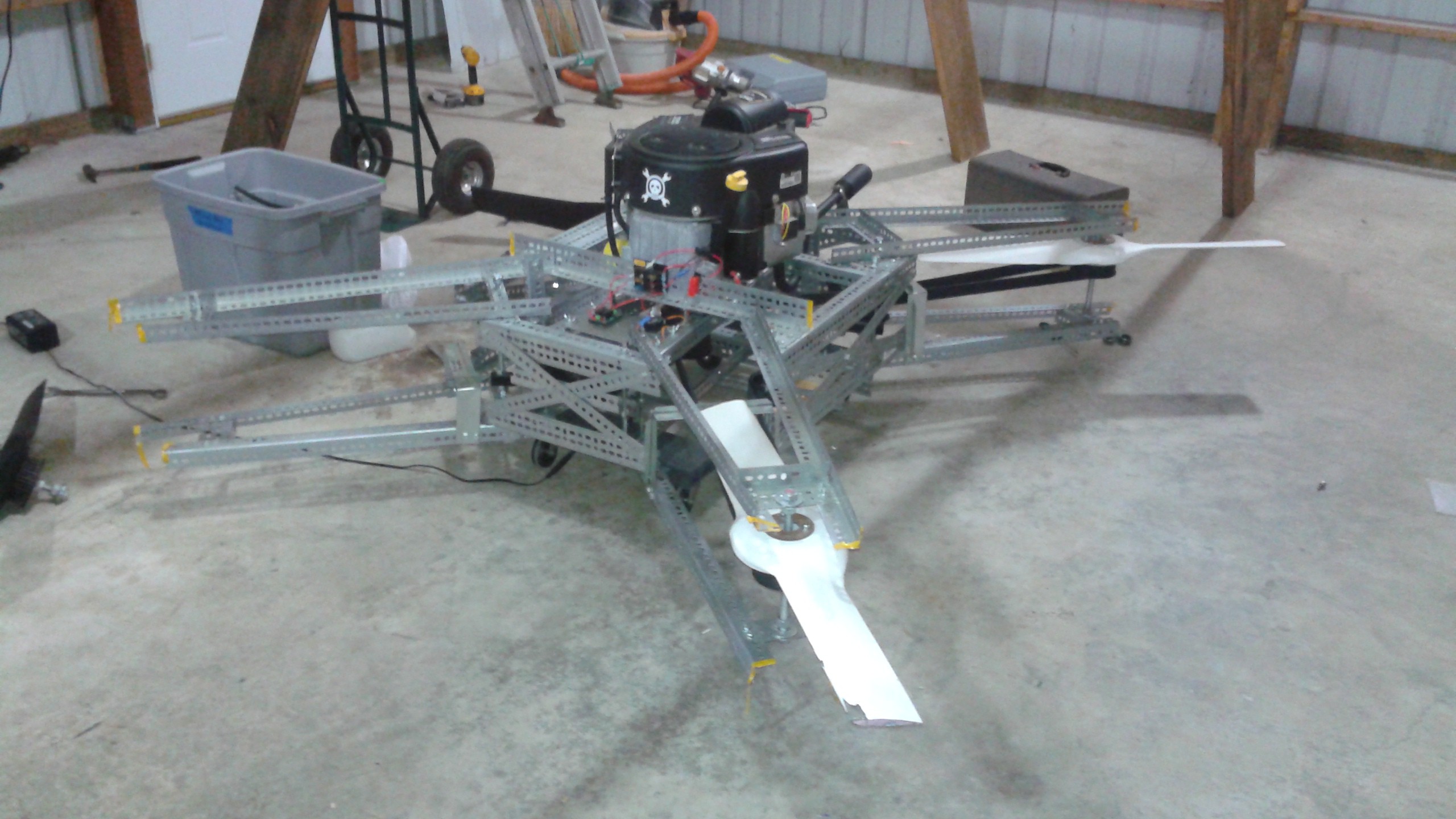
Here's the test stand reassembled inside the new shop in Washington. Goliath is in the center ready to start being reassembled.
The shop is going to be great because now I don't have to deal with the weather and planning around it. Hopefully things will go more quickly once I get started back up again. The downside of the 60 ft long shop? There wasn't a window or a door anywhere near where I wanted to place the test stand. I don't want to create a giant gas powered quadcopter only to asphyxiate myself or give myself carbon monoxide poisoning, so there needs to be some way of venting the exhaust.![]()
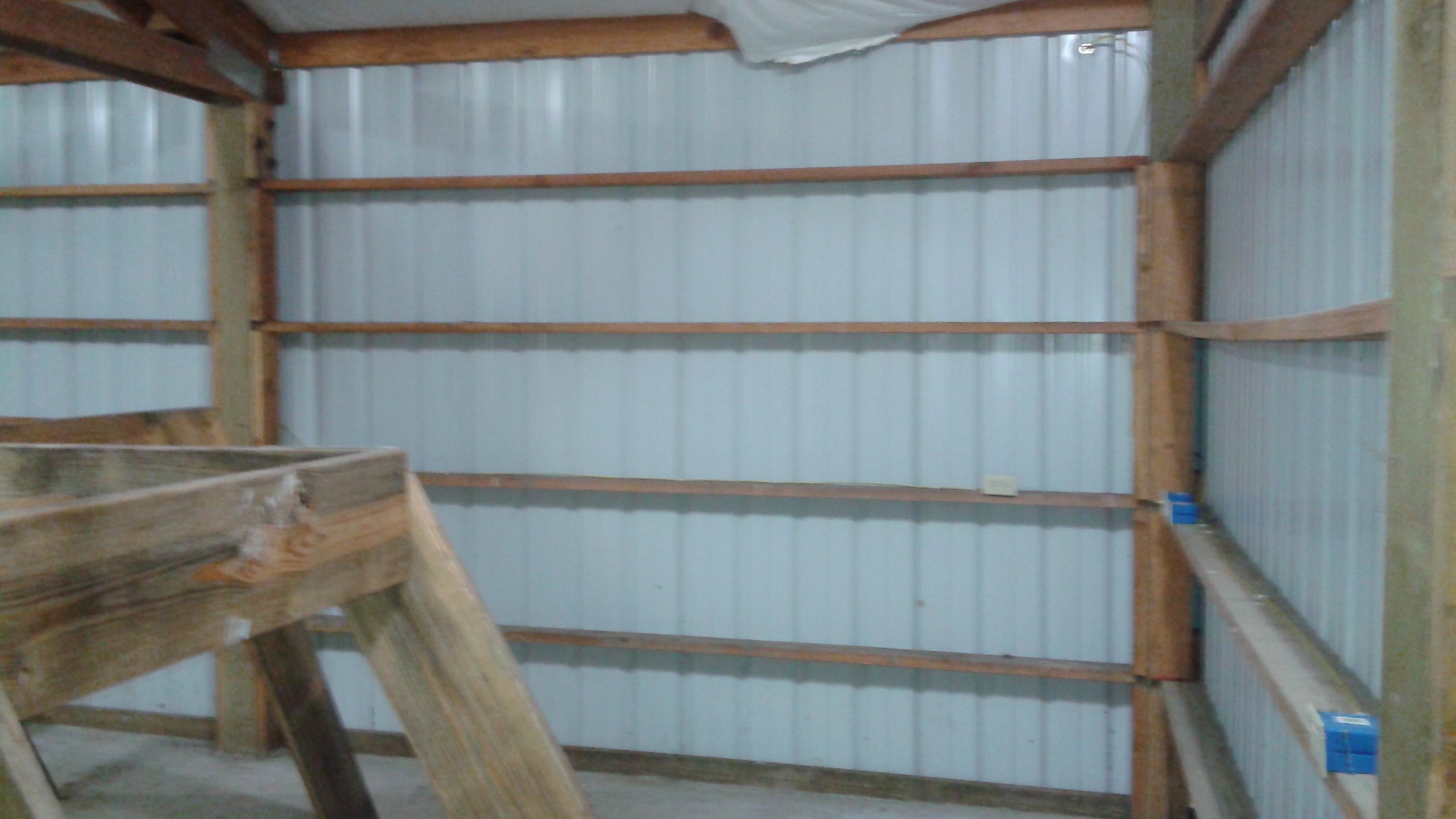
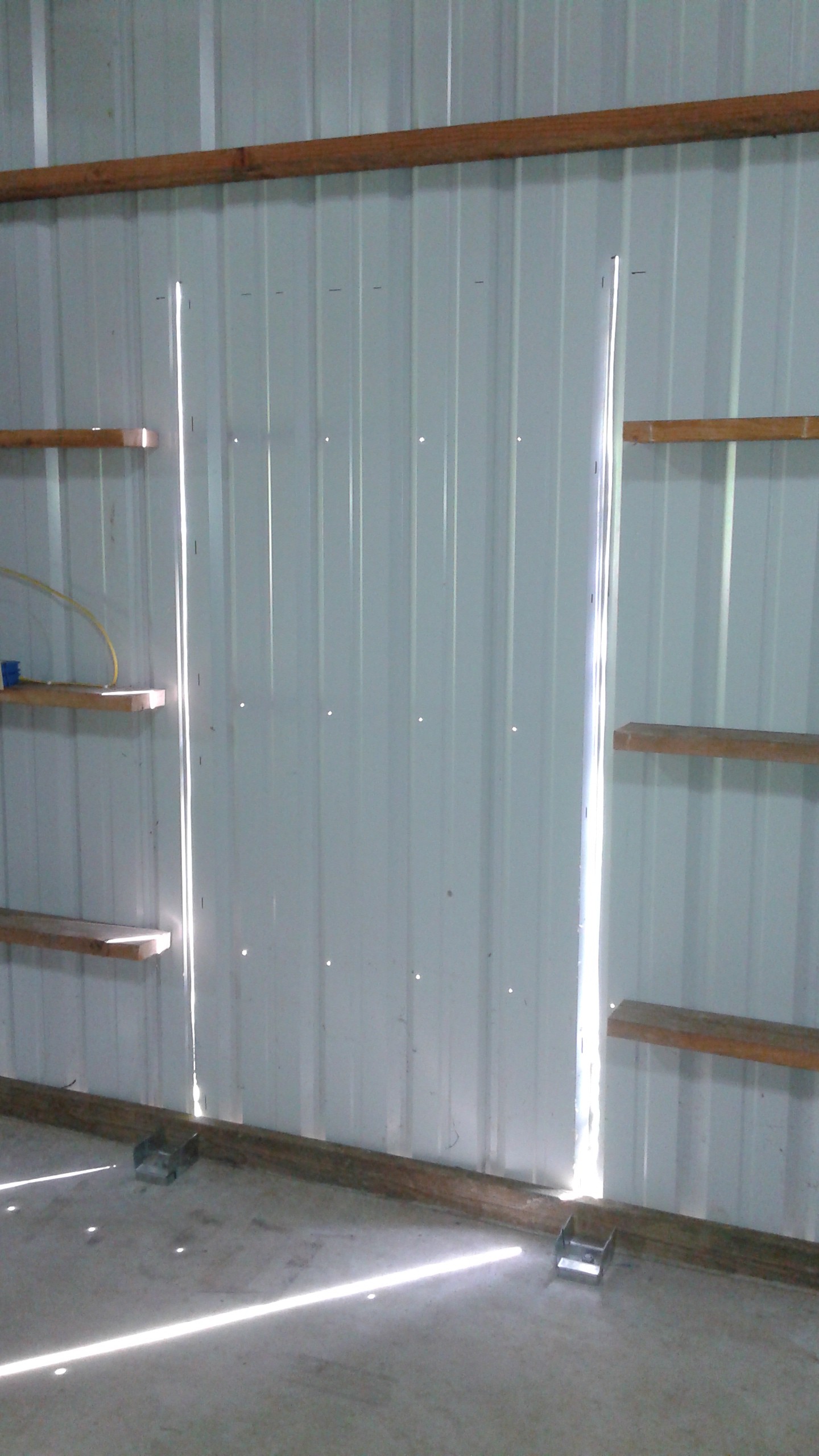
So that brings me to my latest part of the project which is adding a door to this end of the shop. This last weekend I got started by cutting out the door way. Here's the wall where I decided to place the door.
After taking some measurements off the existing door at the front of the shop, I started to cut out the doorway.![]()
![]()
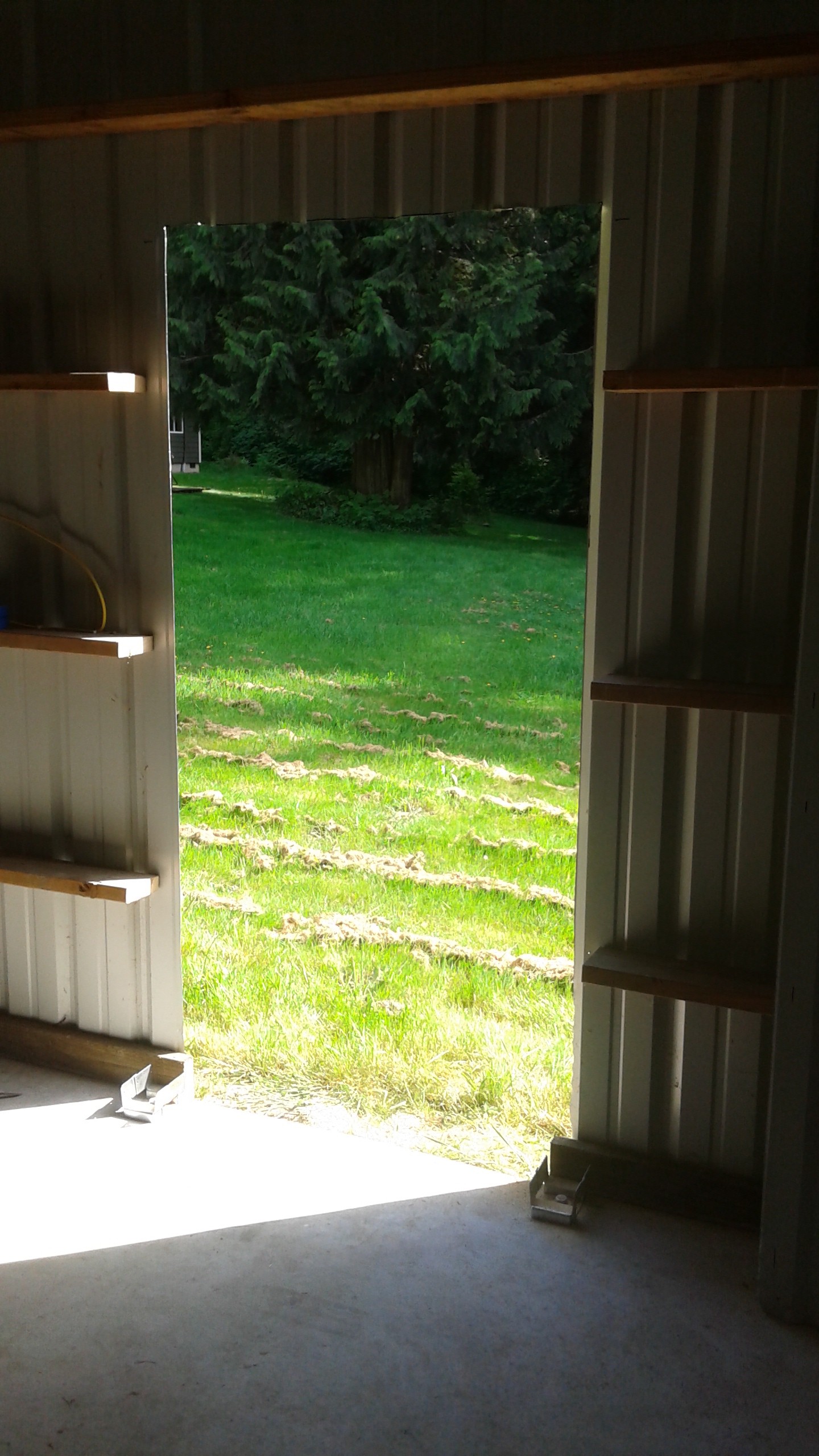
Here is the completed cut out for the door.
The door isn't done yet. I'm waiting to get some trim to close out the edge of the siding and then I can permanently install the new door.![]()
Meanwhile I'm still reassembling Goliath. Right now I've got one one of the belts re-installed and it won't be too much longer before the other one is back on. It's still going to take a while to get everything back together and double checked to start testing again.
![]()
During the down time I also ordered some Grade 8 1/4" bolts from McMaster Carr to replace the bolts that broke previously. We'll see if that fixes the issue of the propeller bolts breaking. Below are the new bolts installed with the old bolts on the table top.
One last note, I took advantage of some of the time away from the shop to organize all the photos for Goliath and started a Flickr page:![]()
https://www.flickr.com/photos/mccloudaero/
I'll be keeping the page up to date with the latest progess, so if you curious where things are at in-between projects logs, be sure to check out things there.
-
We Interrupt our Regularly Scheduled Broadcast...
03/25/2015 at 00:29 • 2 commentsWell, I said I'd be able to fix the vehicle quickly and go back to testing right away. The weather did not cooperate. There was about 4 inches of standing water underneath Goliath on Saturday and it's still drying out. Unfortunately I'm out of time to do anymore testing for a while.
Next week I'll be moving to Longview, Washington about an hour outside of Portland, Oregon. This is the reason has slowed down on Goliath recently. It'll likely be several weeks before I get set back up at the new place, so I won't be posting again until then.
The good news is I'm getting an upgrade in shop space. The new house comes with a 24'x60' shop (below, and no it didn't come with the mill. I did ask though), so I'll have lots more room and I should be able to test Goliath rain or shine (after routing the exhaust outside of course).
![158 Campbell Road, Longview WA]()
The new house sits on 2 acres, so I'll also have enough room to test once Goliath is able to fly.
![158 Campbell Road, Longview WA]() So if all goes well, in a few weeks, I'll have Goliath reassembled in the new shop and get back to testing on a regular basis!
So if all goes well, in a few weeks, I'll have Goliath reassembled in the new shop and get back to testing on a regular basis! -
Progress on the Test Stand and Broken Bolts
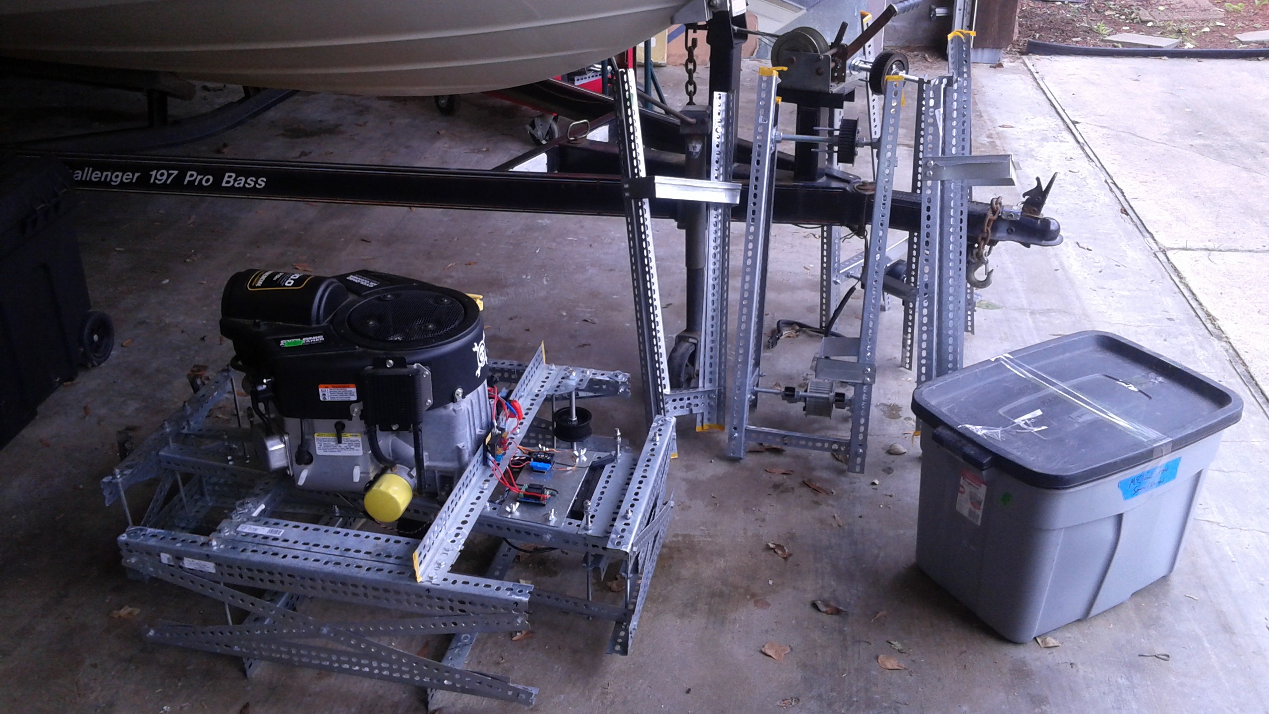
03/21/2015 at 01:47 • 4 commentsThe last few weeks have seen some progress on instrumenting the #Drone Test Stand. You can check out that project for more details, but so far I've made a prototype of electronics to measure the thrust while Goliath is being tested and put together the hardware to incorporate the load cells into the test stand.
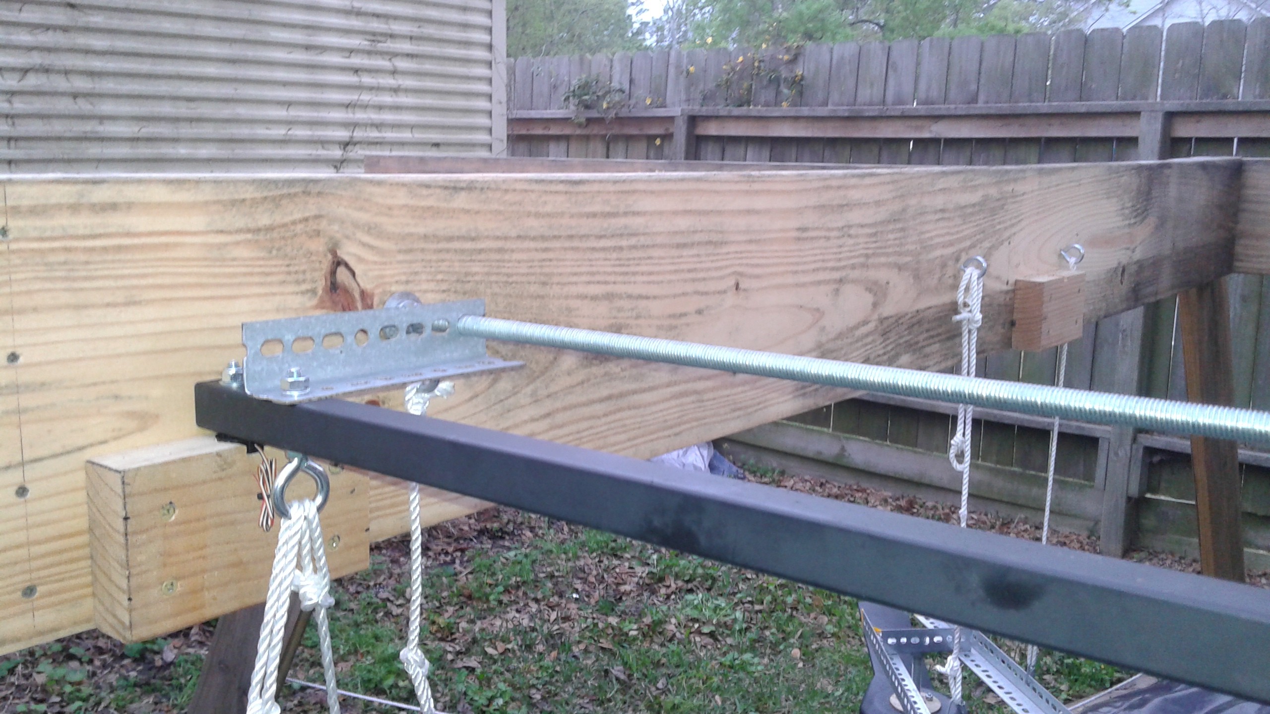
Previously the support lines were directly attached from Goliath to the test stand. The new setup has Goliath attached to two support bars, one for the front and one for the back. Each support stand rests on (2) load cells, one under each end. The load cells are mounted on 2x4 blocks that have a recess to keep the load cells in place. To ensure that the load cells receive a purely axial load, two brackets that swivel on a piece of all-thread hold the support bar in place. The all thread also helps to keep the 2x10s spread apart at the correct distance to keep the support bar in place on the load cells.
![]()
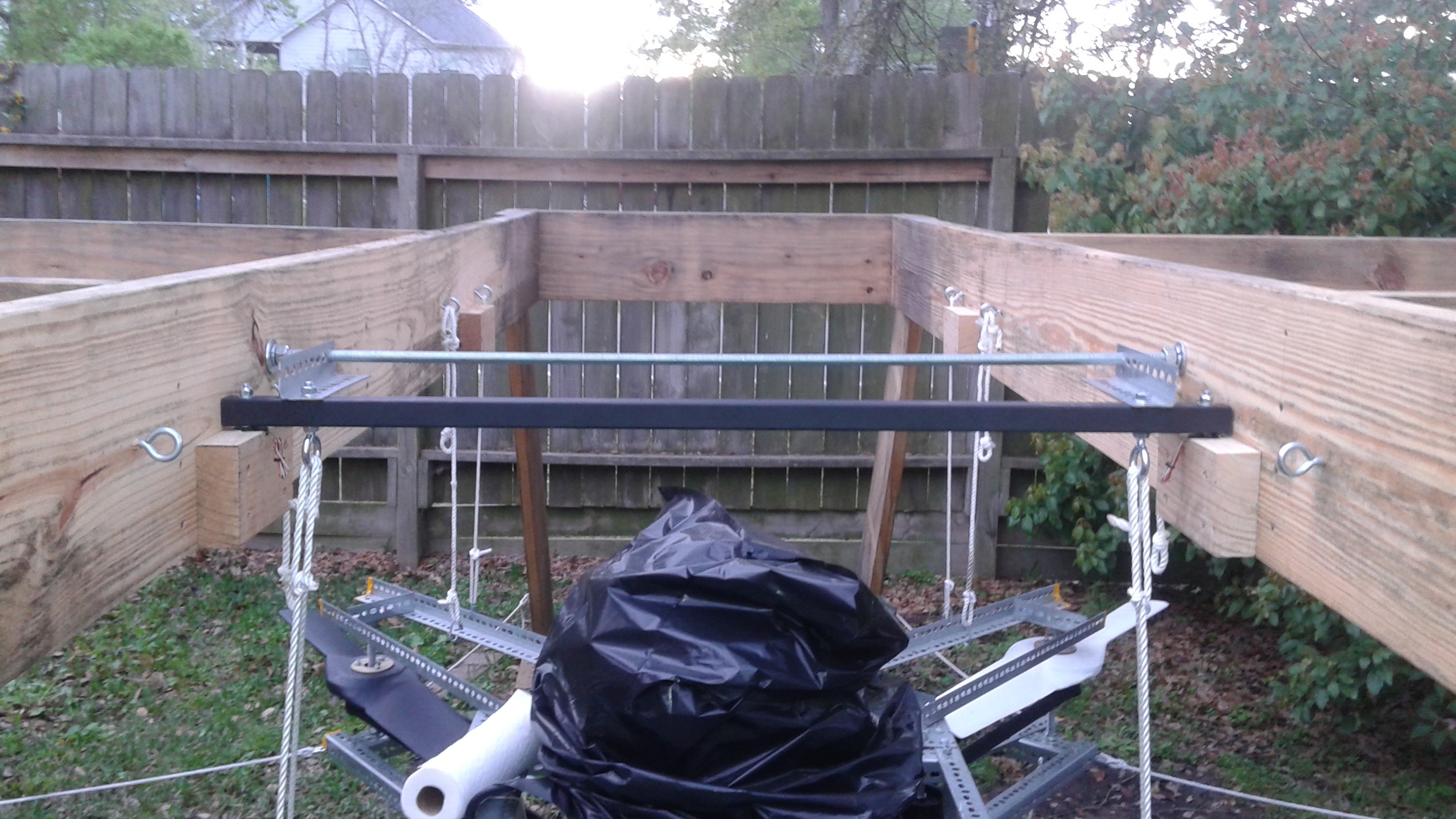
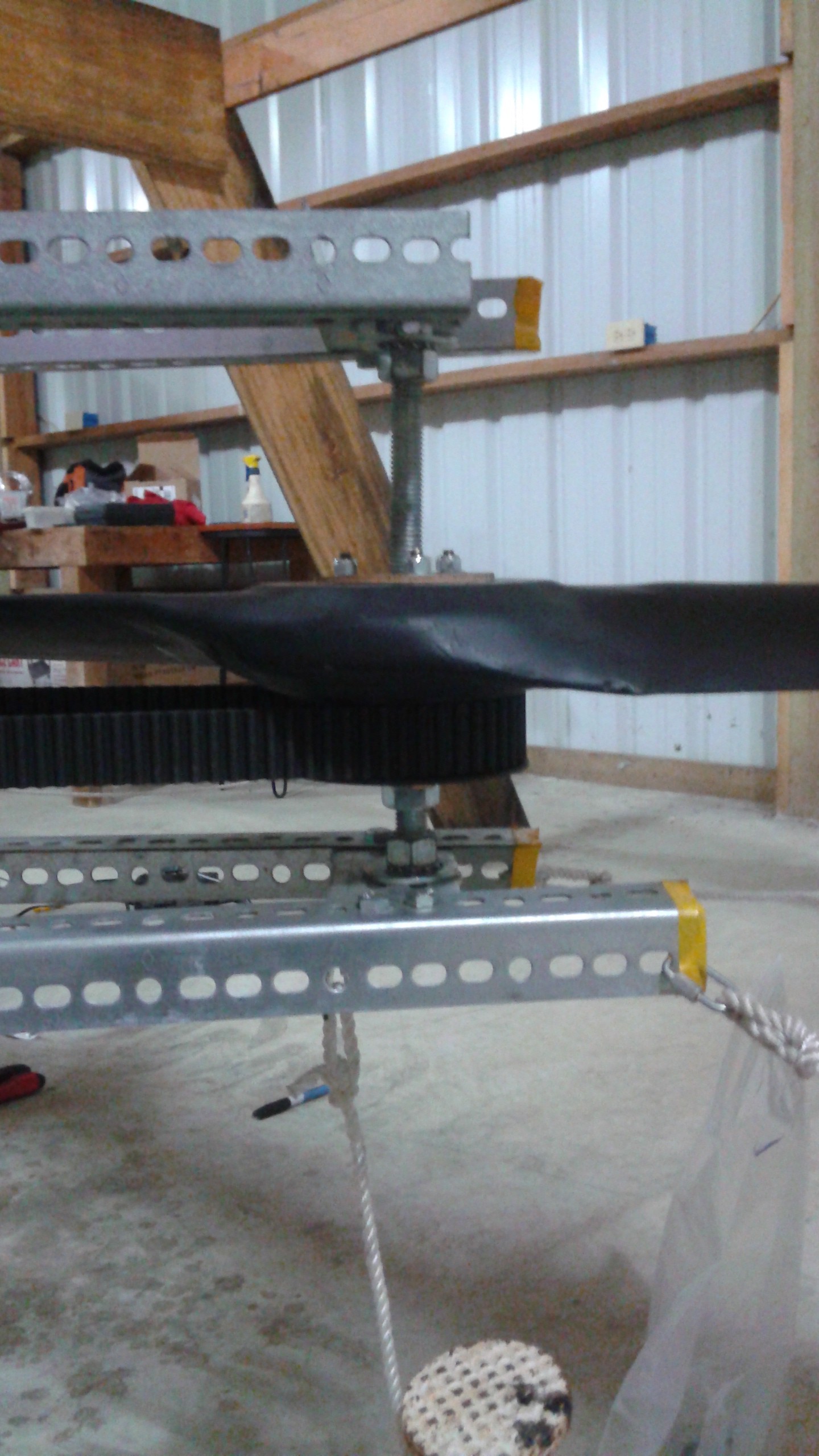
I attached one of support bars to the test stand and decided that it'd be good to run a test with just the one support bar to make sure the setup works before adding the second support.
![]()
The plan for the test was to start up with the choke on, make sure the support bar was okay, and then keep running the engine on idle to warm up the engine. After that I would shut it off and turn off the choke (there's no servo setup for it yet) and then try another run at full power. Here's the video for the test:
As you can see from the video one of the propellers broke free after idling for a while. The propeller broke free after all three of the bolts that hold it onto the pulley failed. Replaying the video after test it was clear that there was a increase in oscillations before it failed. It's likely that one bolt failed and then the others failed under the increase in load. Fortunately having the shaft supported at both ends keeps the prop captive instead of the prop sailing off in the sky. There was no damage to the vehicle other than the three bolts. Here's a closeup of where the bolts broke.
The bolts were just generic zinc 1/4" cap screws 3 1/2" long. The bolt passes through the pulley and are threaded into the QD bushings and hold the two parts together. The bushings come with shorter 1" long bolts for this purpose, but I swapped them out with the longer bolts so that they also served the purpose of the prop bolts. The prop then goes over the bolts and nylon lock nuts go on above the prop to hold it in place. The bolts broke where the prop and bushing interface.![]()
The easiest fix for this is to get higher strength bolts (grade 5 or grade 8). Unfortunately it looks like I'll have to special order them as I need the full length threaded and all the local hardware stores only carry partially threaded. I did find some stainless one today that I can use in the meantime, but stainless is a little weaker than a Grade 5 bolt so I'll just use those temporarily until I receive the others. It should be relatively quick to swap them out at all the propellers, add the second support bar and do the next test.
 Machining steps:
 Obviously this didn't work. Two of the bolts were broken off and one of the bolts was pulled out of the hole. It's difficult to tell exactly what failed first. I suspect that the bolt that got pulled out of the hole didn't have a strong bond and failed first. The load on the other bolts increased, subsequently causing them to fail. Of course it's possible that one of the other bolts broke first and then the rest failed.
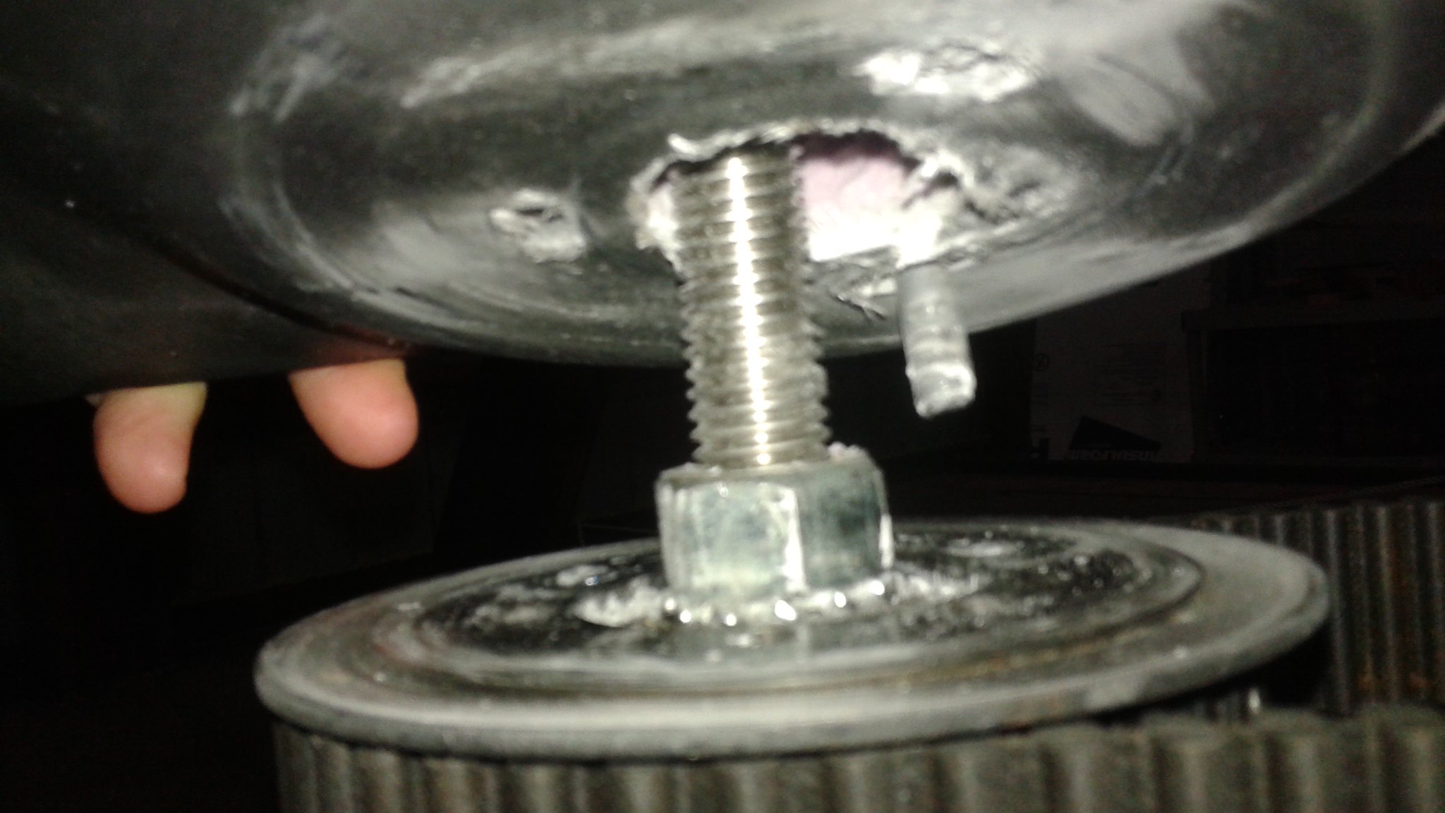
 Connecting the linkage was problematic because the air intake is in the way. Below is a photo with the upper ball link installed and the tight clearances around the linkage. On the right is the side of the carburetor and on the left side is the air intake.
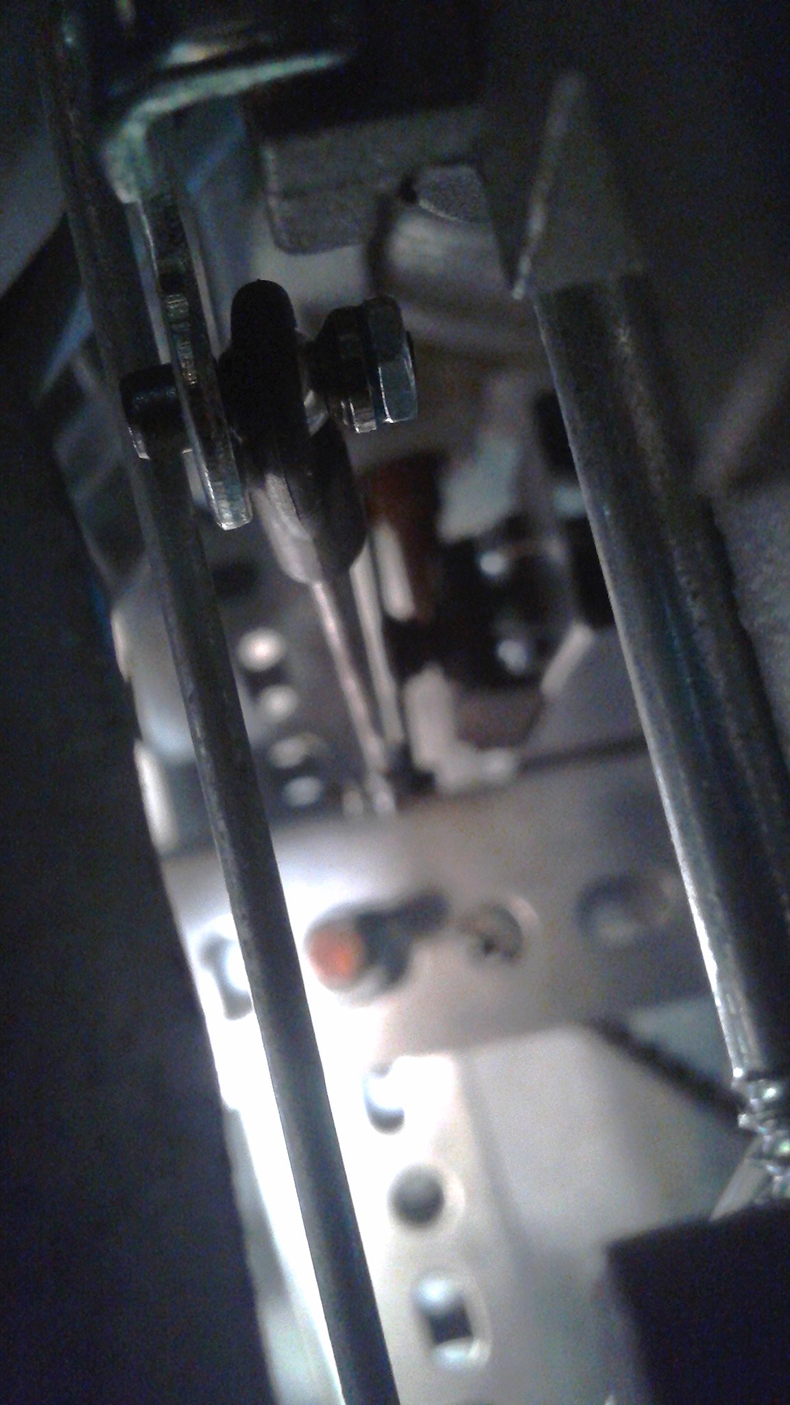 In order to get the nut on the linkage, a special wrench was required:
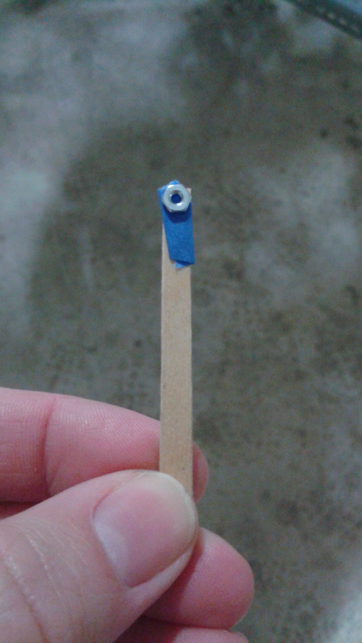

 The pulley stock is 10" long so I can make 7 or 8 30mm wide pulleys with it. It's been a long time since I've worked on a lathe, and I haven't made a pulley before, so we'll see how it goes.
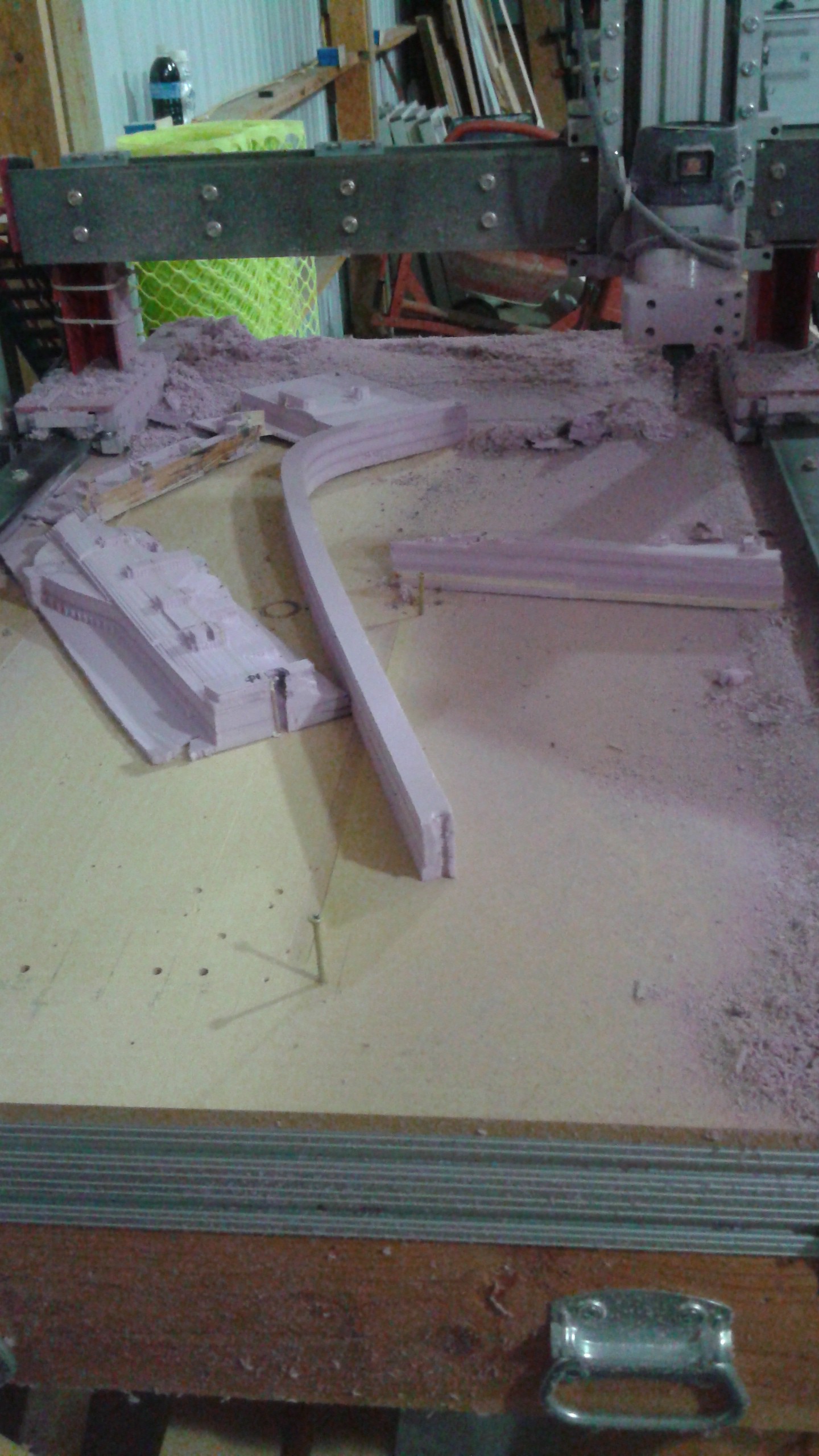


 So if all goes well, in a few weeks, I'll have Goliath reassembled in the new shop and get back to testing on a regular basis!