-
A 2016 alternative to HTCPCP [updated video]
08/15/2016 at 18:44 • 0 commentsAs said before, HTCPCP is fundamentally flawed. In two ways: (1) there is no way the amount of coffee can be controlled, (2) it assumes a teapot cannot brew cofee.
It's time for a new HTPCP-like protocol that solves both of these problems. Things that need to be supported:
- Brewing coffee
- Small talk while deciding if one wants coffee
- Making sure nobody ever believes tea pots cannot make coffee
- At least some control over who is allowed to brew coffee.
As data carrier, pigeons were considered. However, no quality trained pigeons were available, so Telegram was picked. Telegram has a nice bot api. Further, some nice people wrote a Python library for communicating. This solves requirement 4, and eases the development of code for 1-3.
The core telegram bot communication code can be found in telegram.py and may be a useful example to others. The code for implementing requirements 2-3 is also in this file.
The koffiezetter.py has been updated to react to telegram, and to be a little more verbose over telegram, too.
Protocol
As for the protocol, current computers and even the Raspberry Pi have enough processing power to do some amount of written language recognition. Supported commands:
- 'hi' or 'hello': start smalltalk
- some sentence containing 'tea': tell that shamefully we cannot provide tea
- some sentence containing 'one cup of coffee': brew 1 cup
- some sentence containing 'two cups of coffee': brew 2 cups
- shortcut: if it's really early in the morning and coffee is urgently required with lack of proper verbalisation skills, the word 'coffee' provides for 1 cup of coffee
Brewing more than 3 cups over telegram is not allowed (yet) since no phyisical checks are being made before brewing starts. Read: it can get a big mess, and for <=2 cups this is considered an acceptable risk.
Video is updated, as well as the source on Github.
-
Software part 2 - the coffee parts
08/11/2016 at 14:46 • 0 commentsVideo is online! Click here to see the machine in it's full glory.
Arguably the most important feature of a coffee machine is its ability to brew coffee. Thankfully, this machine is actually capable of brewing coffee. Earlier I described the used hardware, in this part I will describe the software.
An advantage of a microcontroller-controlled coffee machine, is that a lot of finetuning of the brewing process is possible. An advantage of an internet-connected coffee machine, is that a lot of statistics can be tracked. For that most exciting part, check http://koffie.ronaldteune.nlAutoBaristaScript (TM)
The brewing code is in the koffiezetter.py module (excuse my Dutch - I tried to at least make it readable with comments). For every number on the quantity dial (1-5), a script is defined:
['Z8','M135','Z16','S60','Z120'] for 1 cup of coffee. This means:
- Give water (Z) for 8/4 = 2 seconds. Due to the control logic, this water is cold. For filter coffee, it's best to first wet the filter. This way, we can spare us the huge effort of doing it by hand.
- Grind (M) 135 half rotations of the grinder.
- Give hot water (Z) for 16/4 = 4 seconds.
- Sleep for 60/4 = 15 seconds. I forgot the fancy 'slow coffee' name for this, but this waiting time after a small bit of water significantly improves the taste of the coffee compared to instantly letting more water pass through the filter.
- Give the bulk of hot water.
The amounts of coffee and water is finetuned for this machine and the beans we currently use. Should we choose to switch beans often, new scripts can easily be created and loaded into the machine.
The temperature measurement comes from the HAL in a scale close to degrees celcius. Measurement is done by an NTC / constant R voltage divider connected to an ADC input of the Atmega daughterboard. I did not calibrate it exactly, but it's close enough. Some trial & error helped in getting the good coffee output temperature.
The script may be extended with a temperature control setting, e.g. to give perfect water for black tea, green tea and coffee. Currently however, a teakettle is still doing a wonderful job for this.
Grinding & brewing process
Both the grinder and the flow meter have two little magnets and a hall sensor. A call back function in the HAL registers the amount of half rotations; the brewing routine waits for the grinding to complete.
The flow meter has recently been installed, but currently the amount of water is still time-based. The clock ticks at 4 Hz (=4 FPS).
More cups of coffee don't mean a linear increase of coffee powder; the amount of powder per cup slightly decreases.
One thing that needs improving is that the Senseo has a three-way-valve that 'spits' hot water back into the water tank when not pumping. This makes both the time-based and the flow-meter-based measurement inaccurate, so the exact amount of coffee is always a surprise. I think I can remove the three-way-valve since my output setup is totally different from the pad-based machine, but I need to investigate it more.
The temperature control is a simple hysteresis based control, with the addition that it tries to leave the boiler at less than 'totally hot' at the end, so the last 2 seconds the water may be colder than in the rest of the cycle. The advantage of this is that the first 2 seconds that are used for wetting the filter can be done by cold water (which means: don't wait for heating up).
The heater starts after grinding the coffee. The advantage is that while grinding, the water tank can be filled without the three-way-valve spitting hot water over the kitchen floor.
-
Software part 1 - the non-coffee bit
08/11/2016 at 11:26 • 0 commentsThe source code of both the software (python) and firmware (atmega, c) can be found on github. It autodetects architecture and can be run on a desktop computer. To make full use of it; an MPD client has to be installed (music), an NS-API token has to be available (train info), and a Dutch postal code + house number combination has to be set (waste collection info). Of course all of this is only neccesary for the home information part, not for making coffee...
The UI will work well enough without all of this. The code has been written to make sure the UI continues to work at most times, catching and mostly ignoring exceptions - because otherwise it's hard to turn the coffee machine off without SSH.
Main
main.py, to which koffieui is a symlink, holds everything together. It loads the different modules:
- System menu (SysD)
- Train time table display (NSDisplay)
- Music player control panel (MPDisplay)
- Last but not least... the coffee maker interface (Koffiezetter)
In this log I will explain the first three of these.
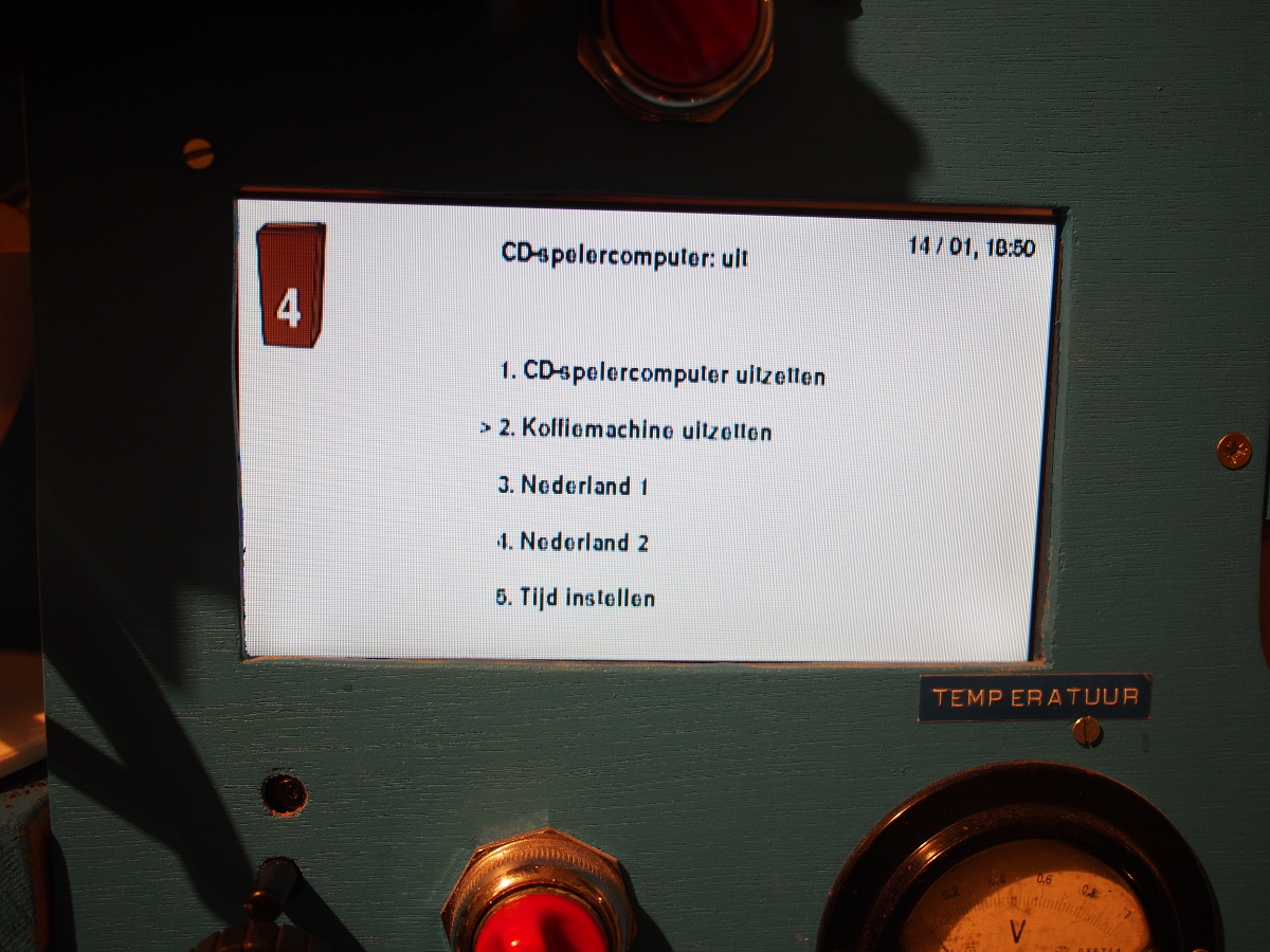
System menu
The source code for the system menu resides in sysd.py. This menu is used to turn off the coffee machine, turn off the cd player computer (=music server), and to watch tv.
It shows the state of the cd player computer (aan=on, uit=off) and also shows if music is available. This is done by checking if it's possible to connect to its apache server. There are scripts to mount/unmount the samba share. I might remove this code, since currently I use snapserver/snapclient for in-sync music playing, the coffee machine not having its own mpd server anymore.
The TV, the three Dutch public channels, are streamed from npolive.nl. After the first implementation, the token authentication scheme changed. The kind people from http://downloadgemist.nl/ helped me out by telling which characters to swap in the token. All the rest I figured out using wireshark. This code is implemented in npo.php, friemelToken(). The code needs changing every once in a while when "they" change their URL or authentication scheme... After getting the stream, it's shown full screen on the coffee machine display using omxplayer.
Hidden in the code is a date/time changer, implemented when I needed to run the coffee machine off network for a while, and I still wanted correct coffee logs. Sadly, it stopped working at some point, probably because of permissions. Currently I don't need it, but the code is still there. Feel free to use it for implementing your own UI.
On the display, the next waste collection type (paper / green / plastic) is shown using an icon of the container and a number for the day count until waste collection. The web site scraping code I developed is in afvalwijzer.py.
The display looks like this:
![]()
Train timetable
Because I used to live very close to a train station, I liked the train time table on the machine, in exact the same way as displayed on the real displays. I used Python-API for fetching the information, and built up the display in nsdisplay.py.
It looks like this:
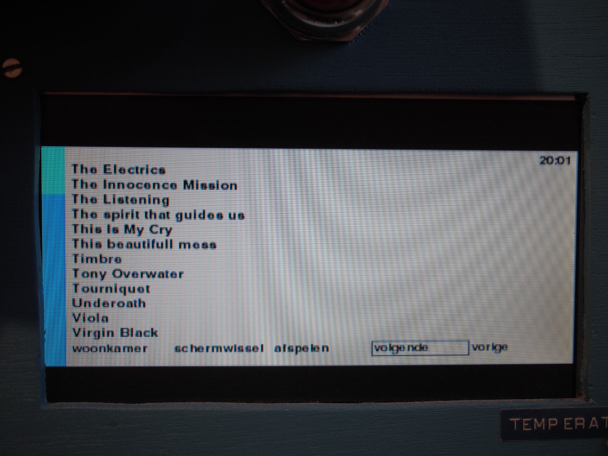
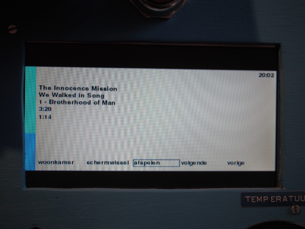
![]() Music player
Music playerFinally the coffee machine is the kitchen's music player. A python fronted was written using python-mpd. All code is in mpdisplay.py. It looks like this:
![]()
![]()
The progress bars used in this UI and the coffee UI are in kwidgets.py, a progress bar library written to make easy progress bars in different colors.![]()
Hardware abstraction layer
The hardware (buttons, temperature 'display', light, counter, and all the brewing hardware and sensors) is abstracted away in myhal.py. The pigpio library is used to access the GPIO's to which the buttons are connected. Additionally, python-smbus allows for accessing the Atmega.
To be able to test everything on a desktop, a simulation is provided in myhald.py. It is automatically selected based on the architecture.
-
Hardware
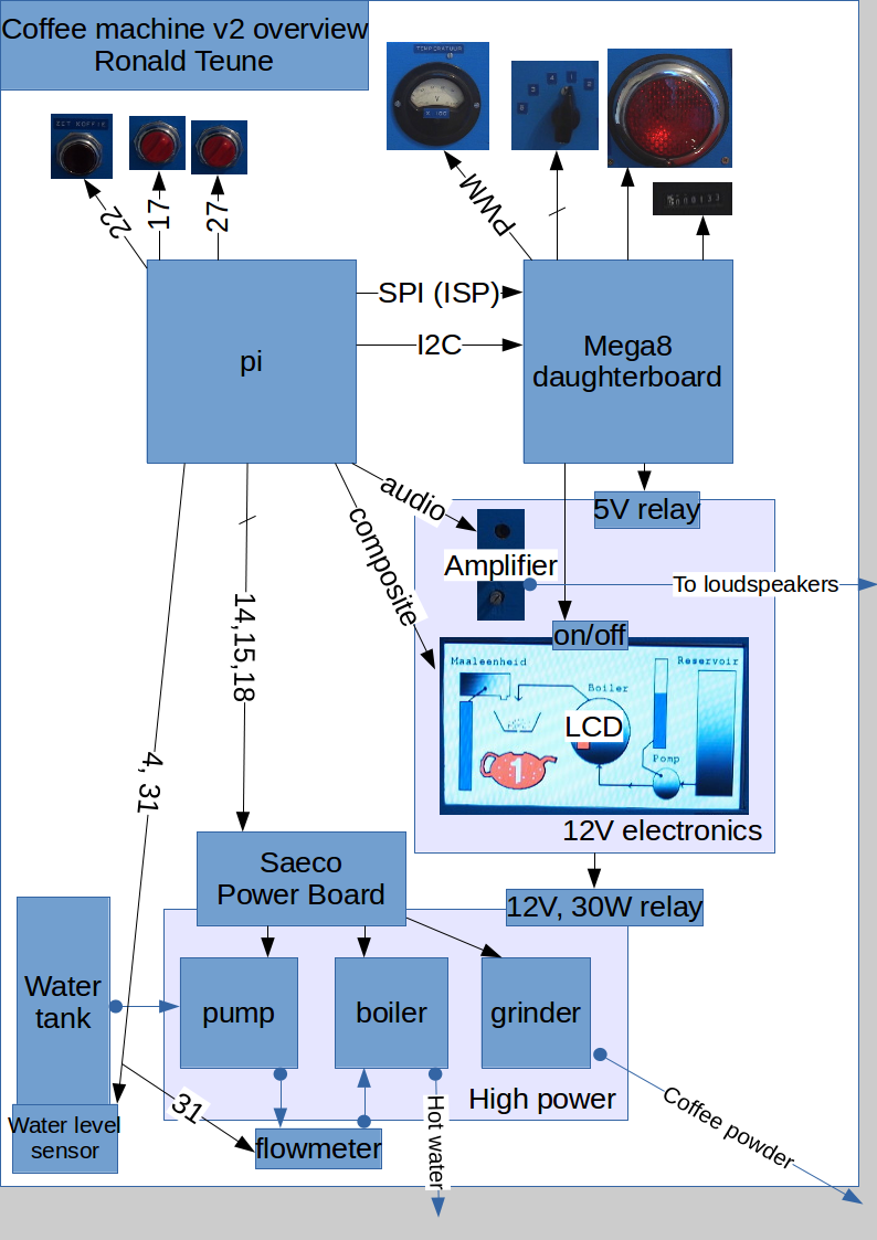
07/28/2016 at 19:29 • 0 commentsBlock diagram
Numbers are Raspberry Pi GPIO numbers.
![]() Power module / grinder
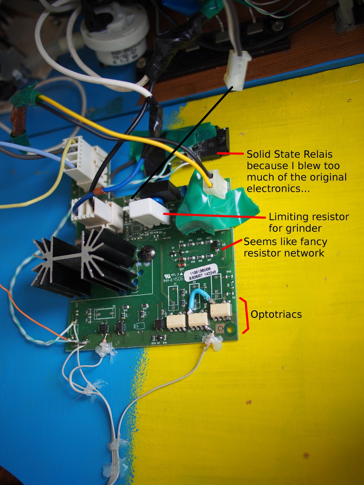
Power module / grinderTo solve the problem in Coffee Machine v1 that after making coffee, the environment was covered in brown dust, I needed another grinder. A friend of mine gave me a Saeco Talea, completely functional except for the corroded boiler.
For the Saeco I found the most extensive Service Manual I ever found for a device. For example, on page 35, they describe their coffee autodose algorithm based on (1) grinder power consumption, (2) pulse (=rotation) count and (3) selected aroma. A wonderful piece of engineering. The quality of the power board, and these fine-tuning mechanisms, made the Senseo look like a toy...
![]()
The power board for the Saeco looks really sturdy. I blew one or too optotriacs, but most of the circuitry I was able to reuse. The fancy resistor network is probably for measuring the power? But I don't use it (yet) since I can fine tune in code when needed. The big, heatsinked part is the final stage for the boiler. The lower power parts just have one simple optotriac stage.
For pump, boiler + heat sensor, water tank + level sensor reed relais, I used a Philips Senseo HD7800 with all the electronics removed. The boiler has a heat fuse switch next to the NTC, that's safe enough for me. No pictures of this part; many pictures are in the Repair Cafe Senseo Repair Manual made by hobbyists.
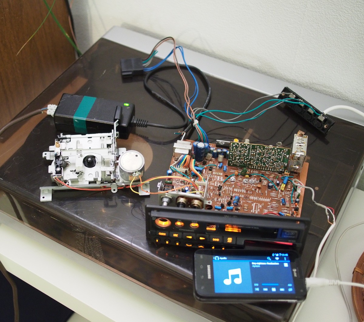
Audio
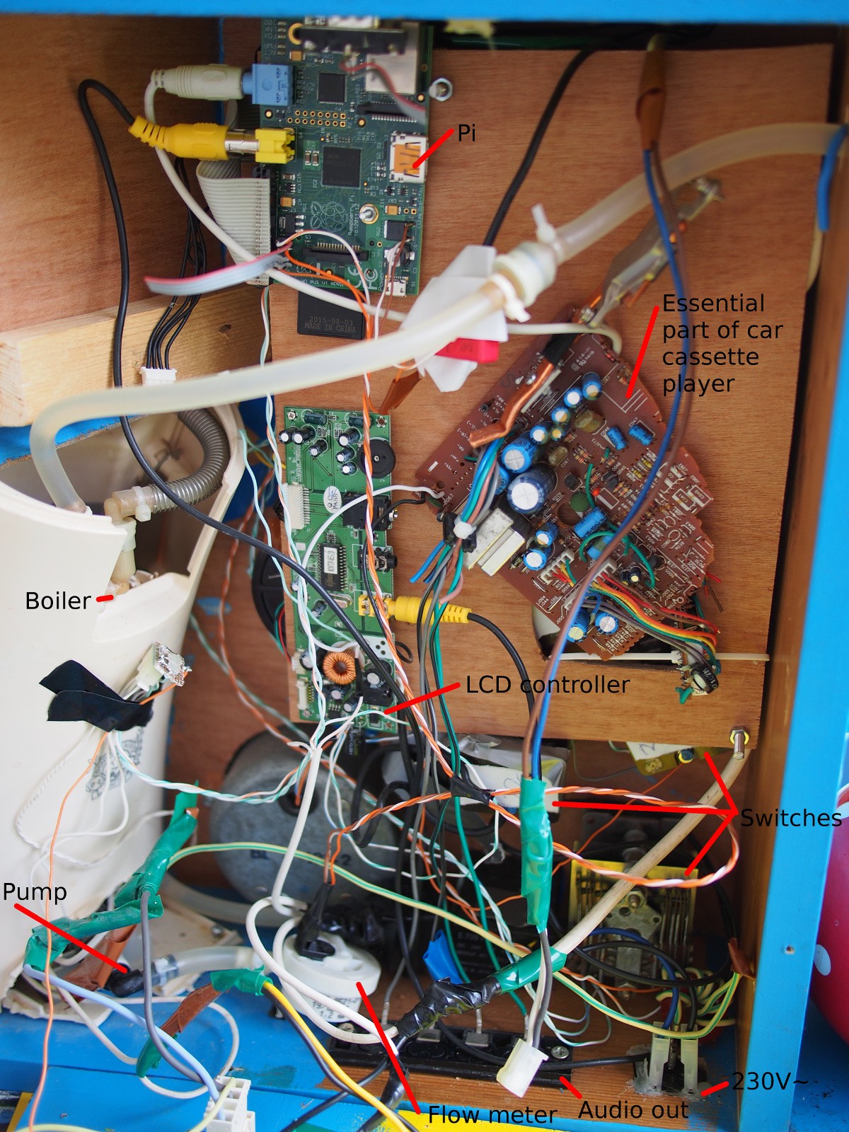
To remove the need for a separate audio system in the kitchen, I decided to build an amplifier inside the coffee machine. For this I used part of a car cassette system. Firstly I connected my phone to the cassette output, after that I traced the wires using the GIMP and semi-opaque layers of the front and the back of the PCB, to be able to cut off all but the essential parts.
![]()
![]()
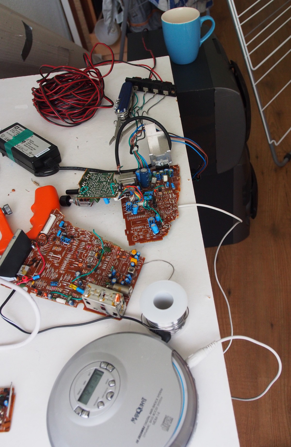
The internals
Work in progress... :) Testing the LCD, audio, power electronics.
![]()
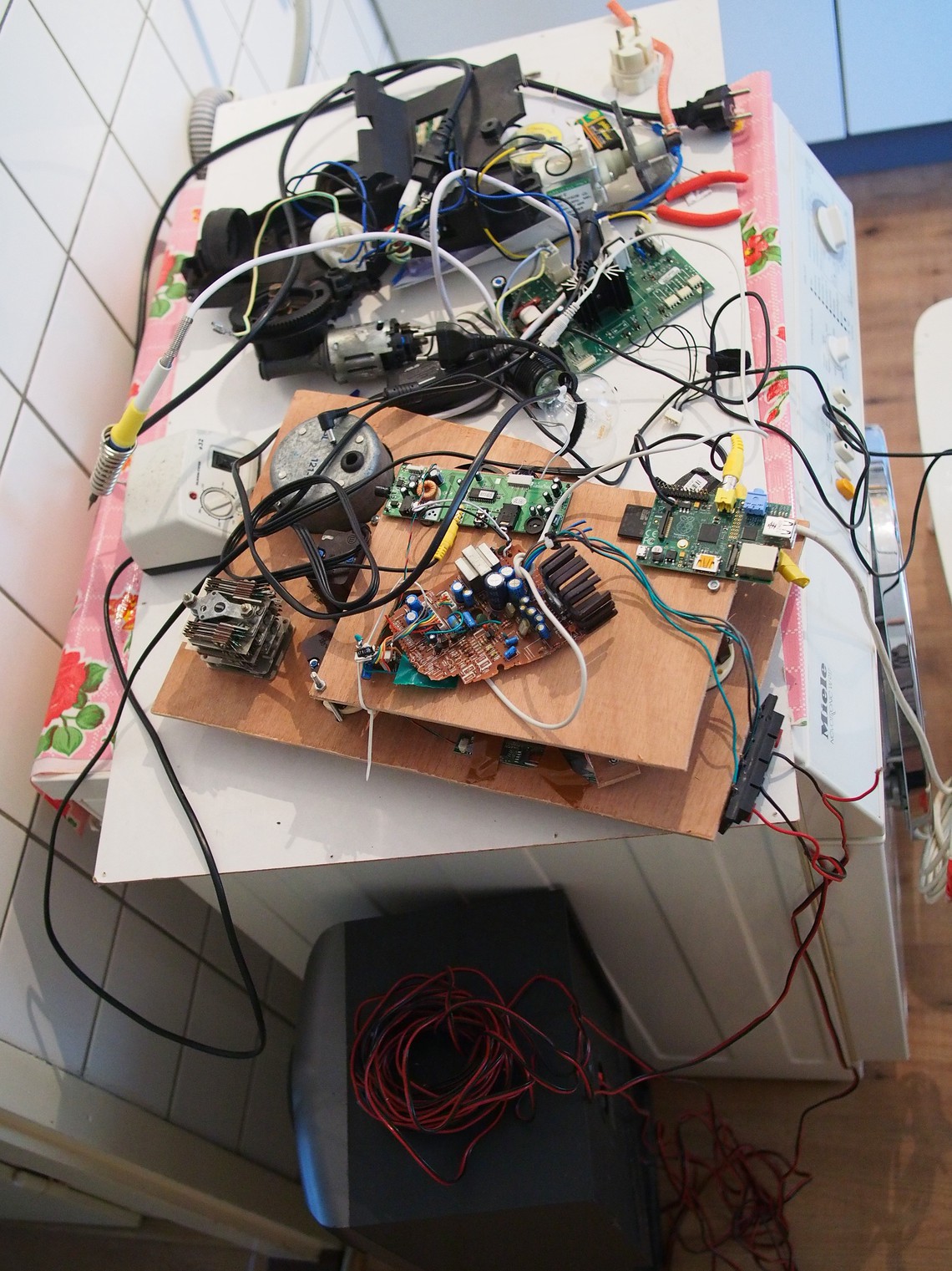
Fully built:
![]()
Both the flow meter and the grinder have a two little magnets inside, using a hall sensor to count the number of half rotations. The LCD controller + panel comes from a portable DVD player. Sadly only with 480x234 resolution...
Behind the wooden panel are the switches, and the RonaldBoard Mega8 daughter board. I forgot to take pictures of it, but it's not *that* exciting (and taking it apart again is quite some work...).
The 1-2-3-4-5 switch at the bottom right in this picture is actually a switch with 12 positions - of which only 5 distinct positions can be discerned after the years of usage before it ended up in a thrift store in Prague.
-
RonaldBoard: ISP programming + I2C communication
07/14/2016 at 14:00 • 0 commentsAt the time when I started this project, there was no single project I could find, that combined ISP and I2C communication. So I decided to do it myself. Since everything needs to be enboxed and I still want to be able to upgrade firmware from SSH, ISP needs to be possible "without hands".
warning - warning - warning - warning - warning - warning - warning - warning - warning - warning
This can kill your Rasbperry Pi, be especially careful with 5V-linesFor the coffee machine this board will handle PWM and ADC, things an ATMega8 is better capable of than a Raspberry Pi.
Since Gert named his expansion board GertBoard, I decided to name mine RonaldBoard (as a fellow Dutchman? At least Gert's name sounds Dutch...).
All that's needed is: a Raspberry Pi, At*, and wires. For the Pi I chose the ATMega8 rather than ATTiny45 because of having some more cheap I/O.
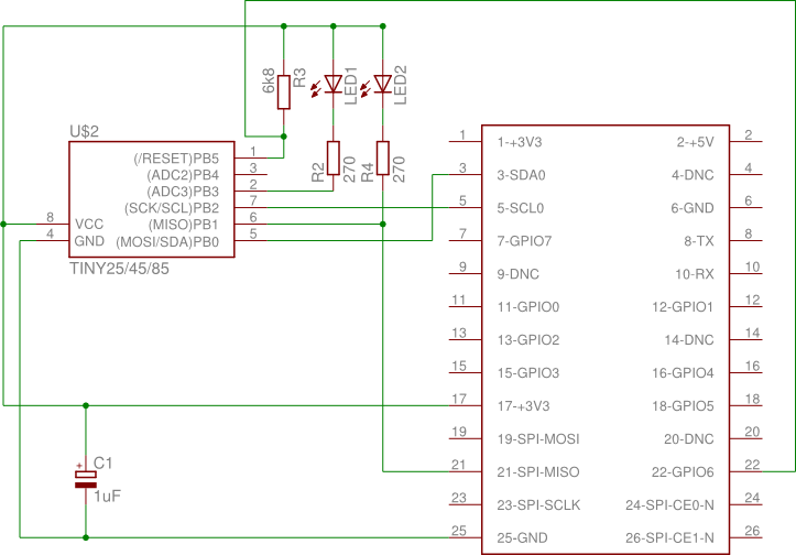
The design is as follows:
![]()
Note! While the pin numbering is okay, the GPIO numbering is wrong! Check [1] for correct info
- The /RESET pin is connected to pin 22 of the GPIO-headerPB0 doubles as SDA (I2C communication) and MOSI (ISP) pin
- PB1 is connected to MOSI, and can be used with care to drive something else when not in programming mode (an LED in this example)
- PB2 doubles as SCL (I2C communication) and SCK (ISP) pin
- PB3 is connected to an LED
Note that because PB1 is used by the Pi when programming the ATTiny, it probably shouldn't be used to e.g. drive a Servo using PWM.
For Pi <=> Atmega8 communication I chose for I2C, because at the time, I couldn't get (non-bit-banging) SPI working. For the Tiny45 the pins are the same; for my ATmega8 this cost me two additional pins...
Set up
If you want to use this in your own project, be sure you have the following:
- Raspberry Pi connected to the RonaldBoard
- The pigpio library installed
- avrdude (patched version)
- Example source (check project files for I2c.tar.gz)
- /etc/avrdude.conf configured with the pgio programmer on the correct pins:
programmer
  id    = "gpio2";
  desc  = "Use sysfs interface to bitbang GPIO lines";
  type  = gpio;
  reset = 25;
  sck = 3;
  mosi = 2;
  miso  = 9;
;
Usage
Before the first run after boot, be sure pigpiod is running and you have the i2c module loaded. I made the following script:
After all is set up, flash the RonaldBoard:sudo ./modprobesmake sudo make fuse sudo make flashThe Makefile makes sure the GPIO's for I2C communication are set to read again, using pigs-commands.
Then test it:
./i2ctestYou should see something like this in your terminal window:
i2cdetect:
     0  1  2  3  4  5  6  7  8  9  a  b  c  d  e  f
00:          -- -- -- -- -- -- -- -- -- -- -- -- --
10: -- -- -- -- -- -- -- -- -- -- -- -- -- -- -- --
20: -- -- -- -- -- -- 26 -- -- -- -- -- -- -- -- --
30: -- -- -- -- -- -- -- -- -- -- -- UU -- -- -- --
40: -- -- -- -- -- -- -- -- -- -- -- -- -- -- -- --
50: -- -- -- -- -- -- -- -- -- -- -- -- -- -- -- --
60: -- -- -- -- -- -- -- -- -- -- -- -- -- -- -- --
70: -- -- -- -- -- -- -- --
test in getting the value of register 0x42:
0x42
testing ADC read:
0xc0
0xd5
0xb7
testing PWM.
Furthermore, the LED should turn off and then shine brighter and brighter.
Used work
Eagle libs for the ATTiny & Pi (both modified afterwards in Inkscape, but very useful for the basic symbol):
- http://bienonline.magix.net/public/undsonst-eagle.html
- http://bioserver.her.hcmr.gr/RaspberryPi.html
Libraries:
- usiTwiSlave by https://github.com/eriksl/usitwislave
- The pigpio library: http://abyz.co.uk/rpi/pigpio/
- Using GPIO for avrdude: http://blog.stevemarple.co.uk/2013/03/how-to-use-gpio-version-of-avrdude-on.html
Coffee machine v2
Automatic Slow Coffee Machine | home information device | music player
 Music player
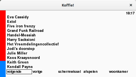
 Power module / grinder