-
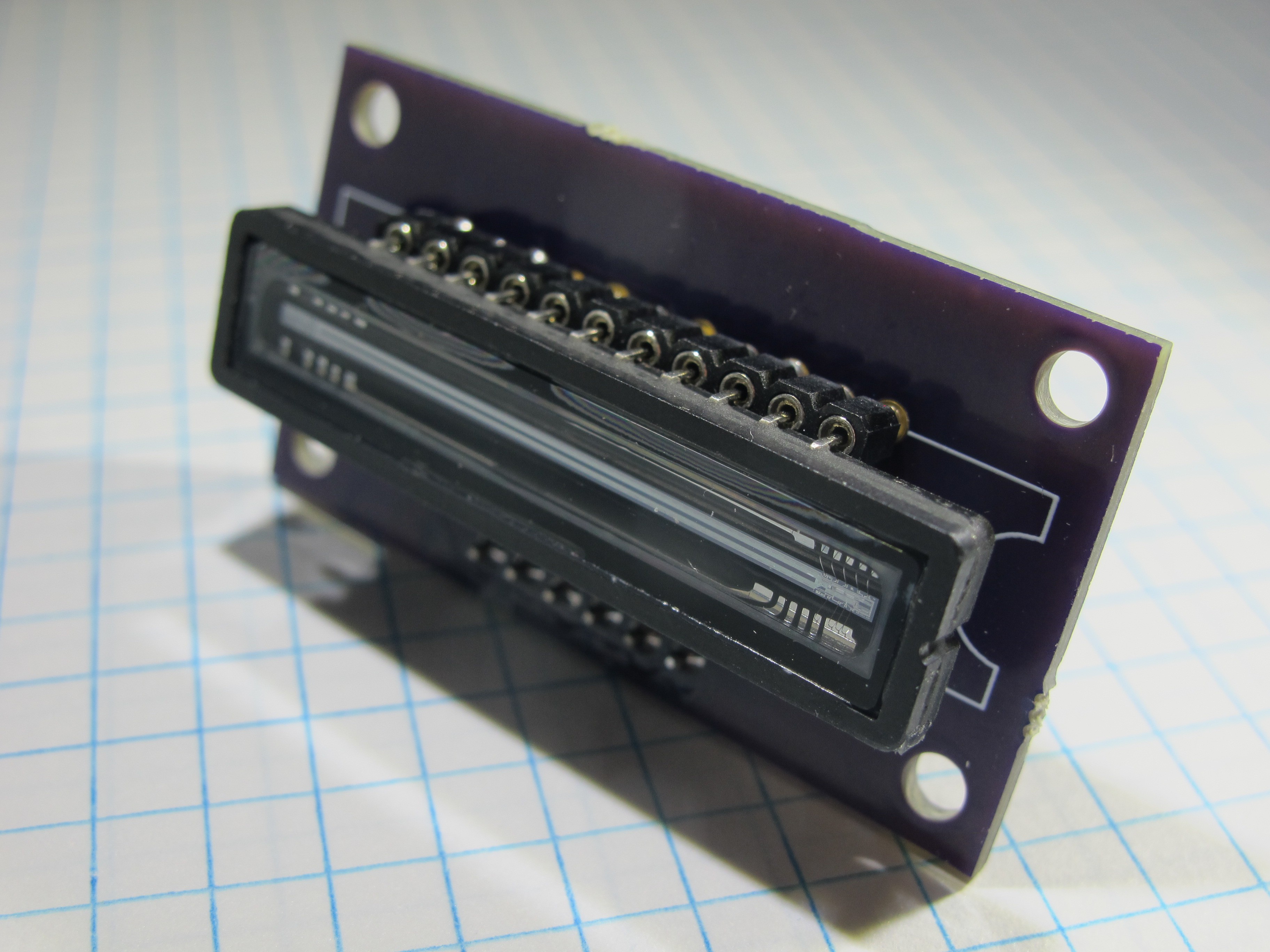
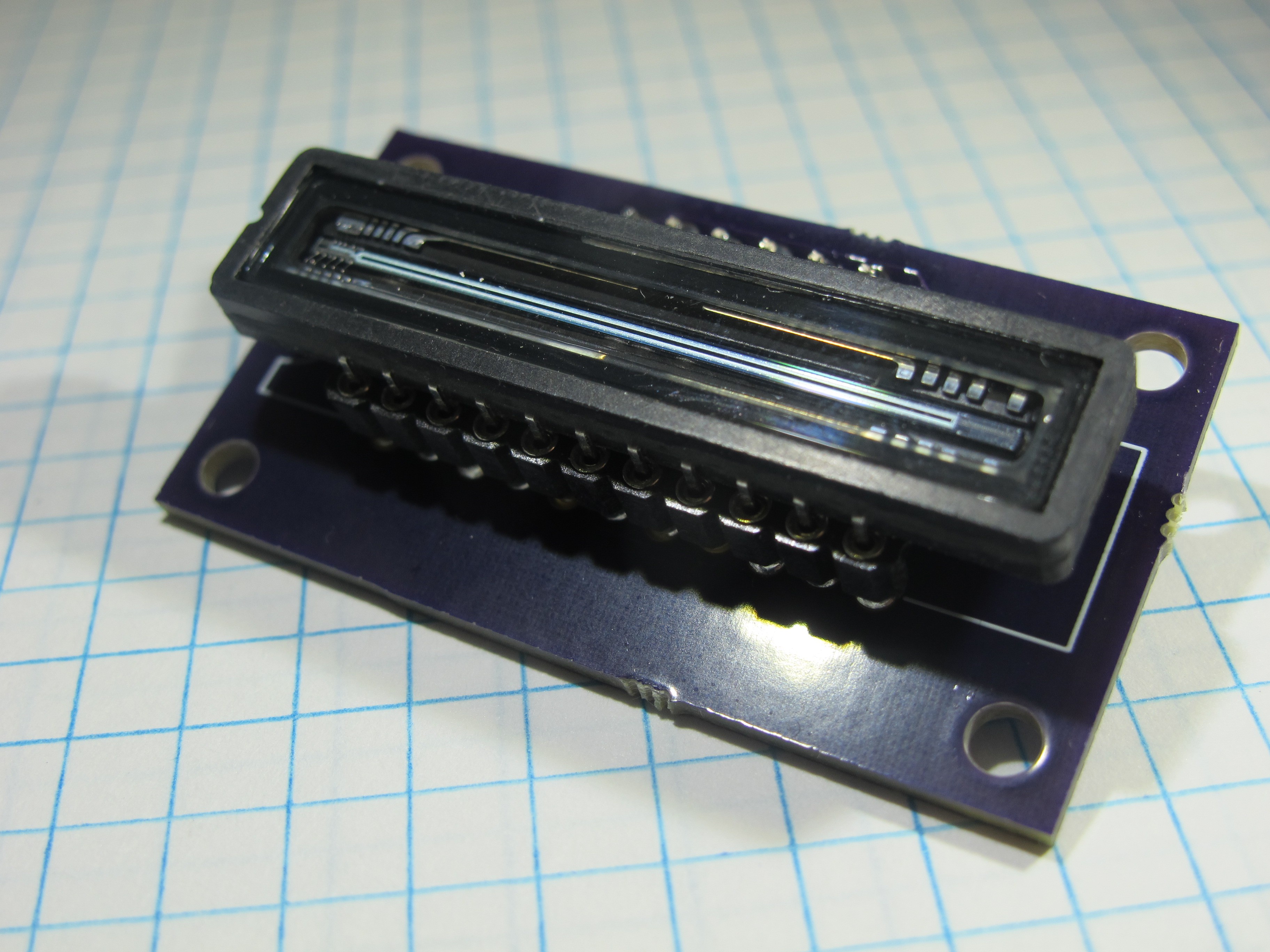
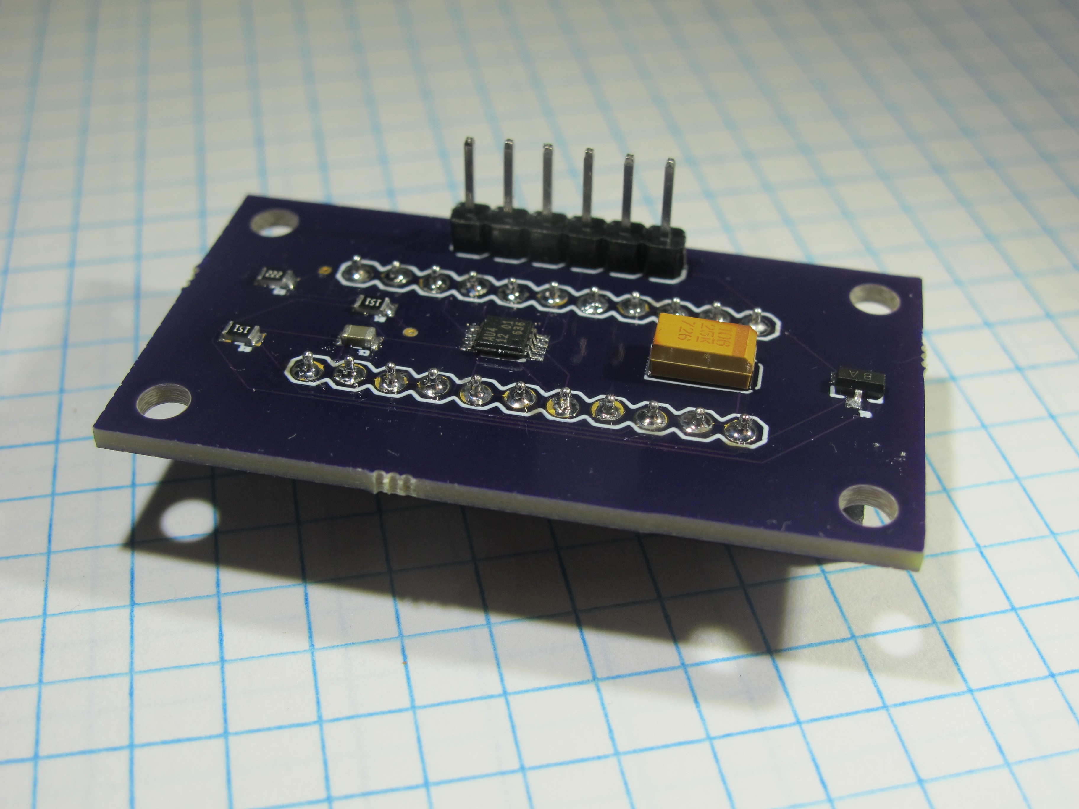
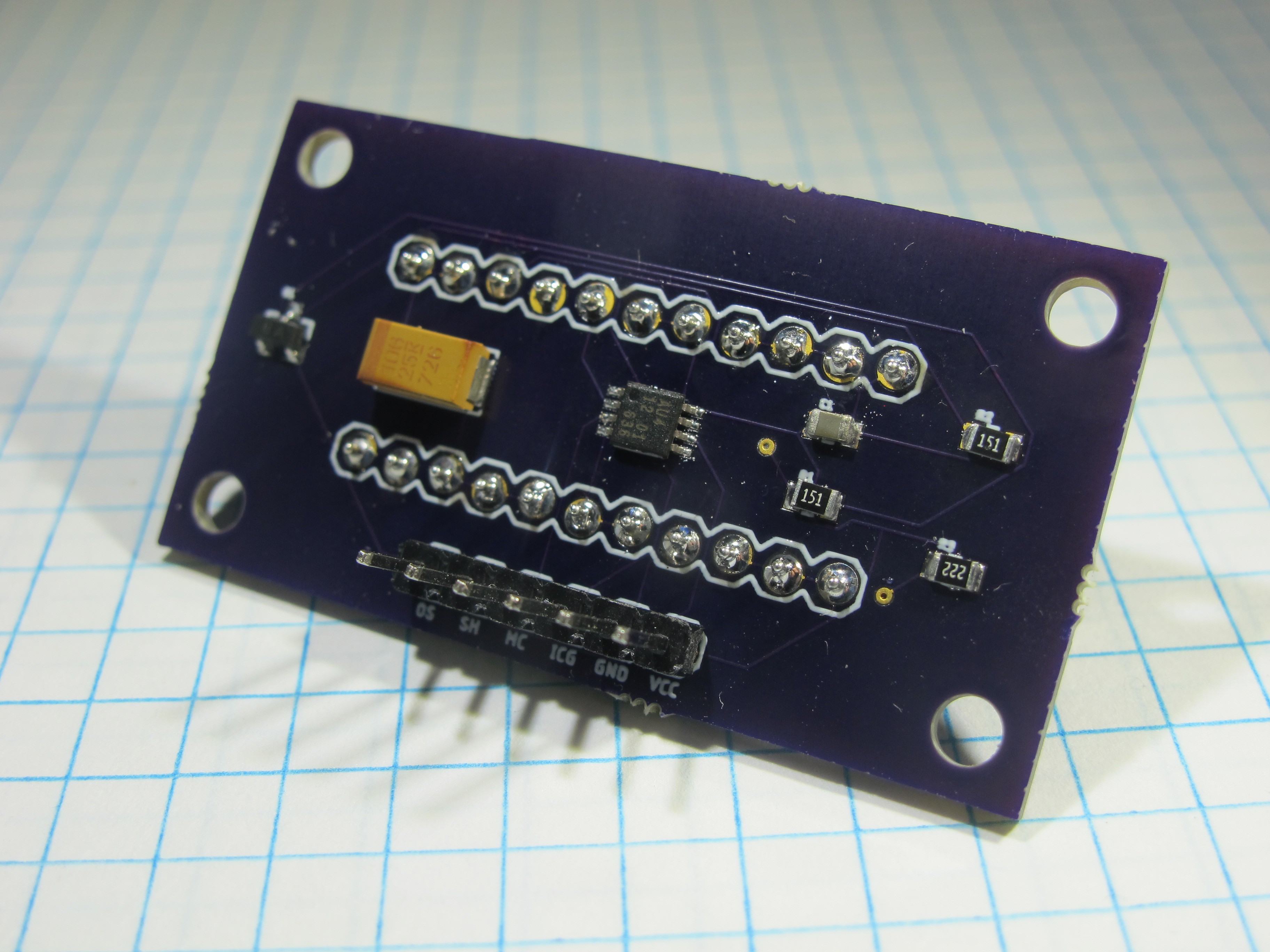
Toshiba TCD1304
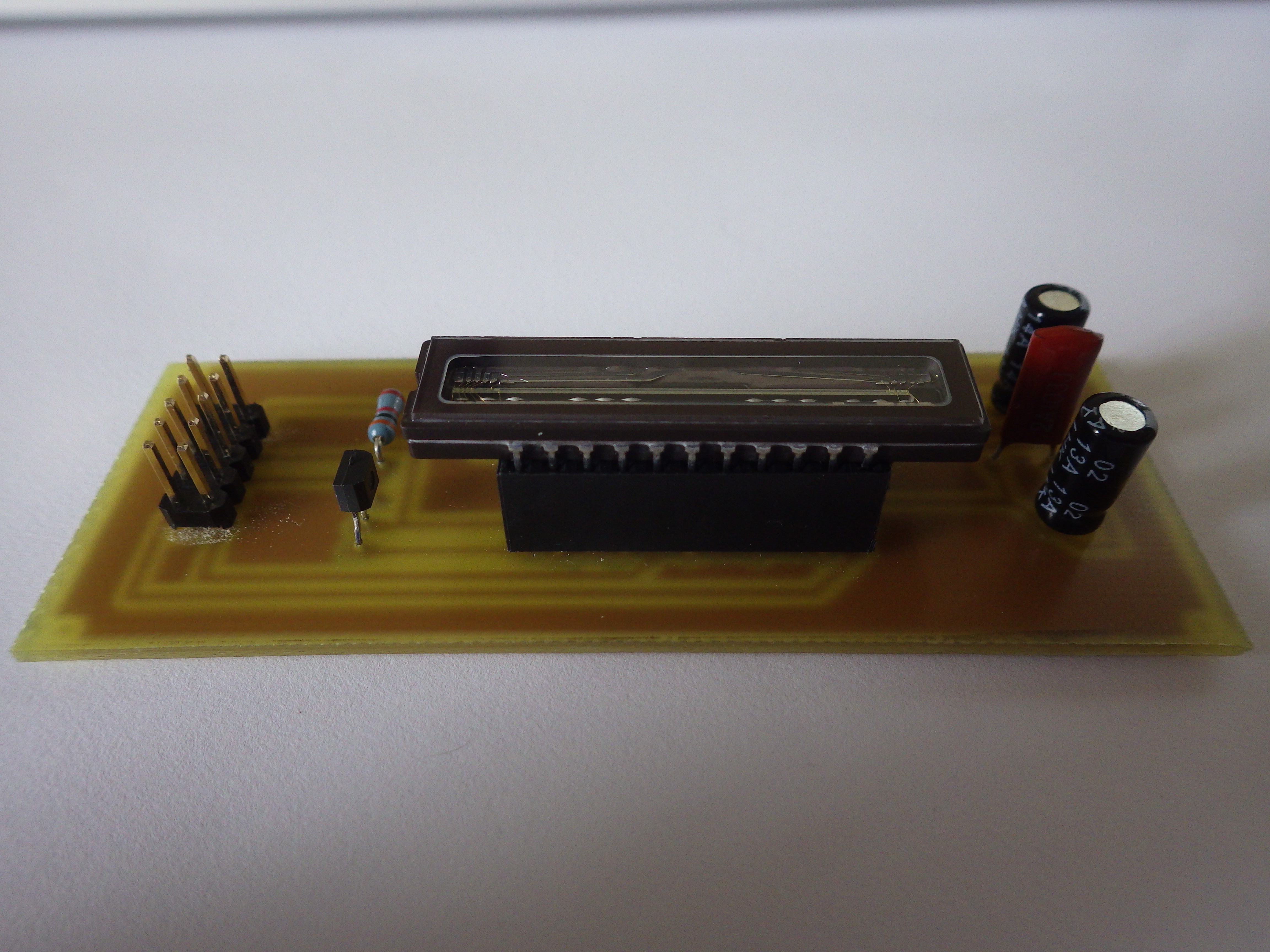
02/26/2018 at 15:15 • 2 commentsFor a number of reasons including product availability and cost I decided to swap out the Sony ILX11B CCD in my spectrometer for a Toshiba TCD1304. Additionally there are a number of other DIY spectrometer projects that use this part making it easier to develop code to drive and read from the CCD. Because of timing requirements on the TCD1304 I can no longer use an Arduino Nano to drive the CCD and plan on using a Teensy 3.6.
-
3D printed enclosure prototype
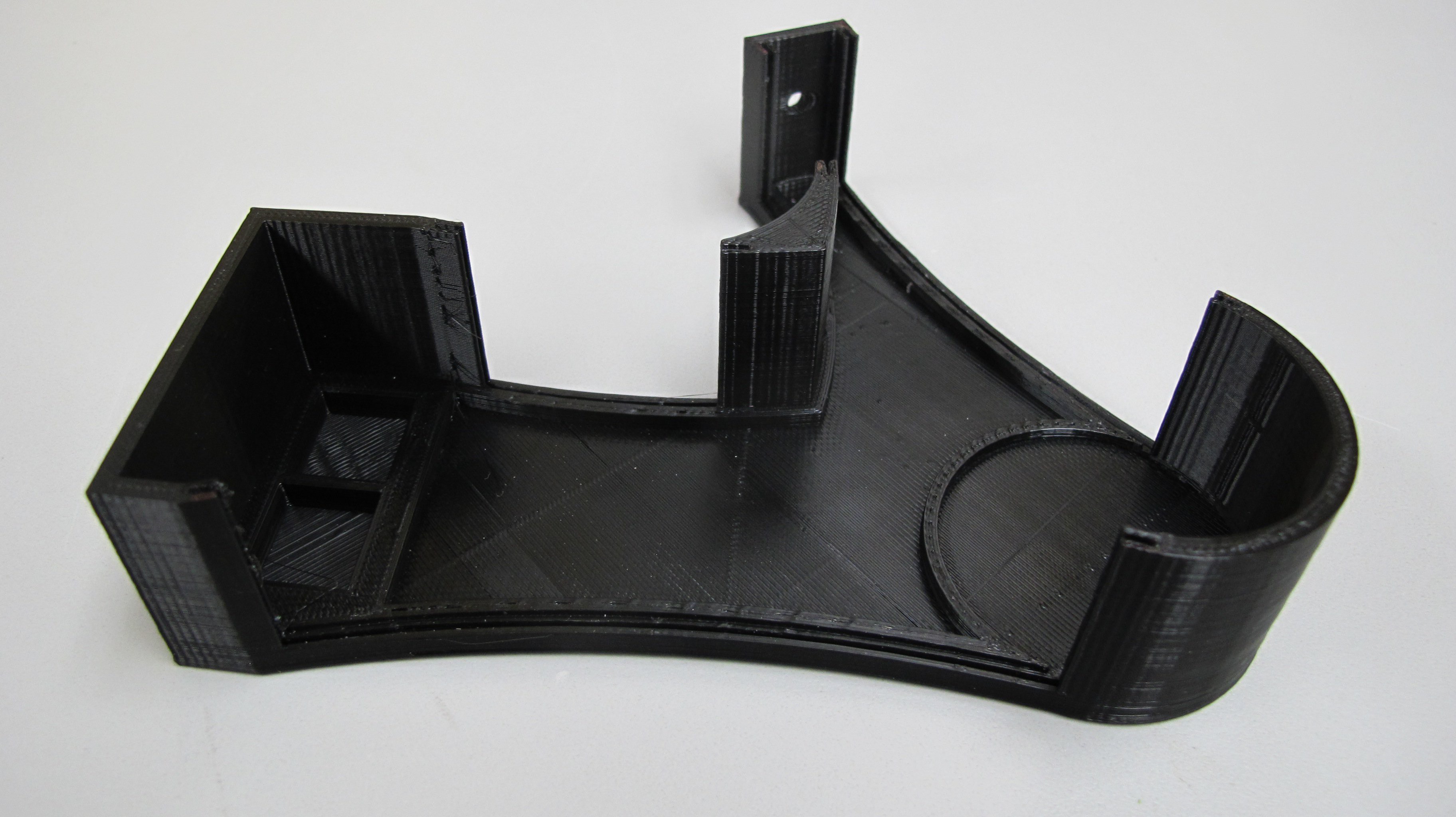
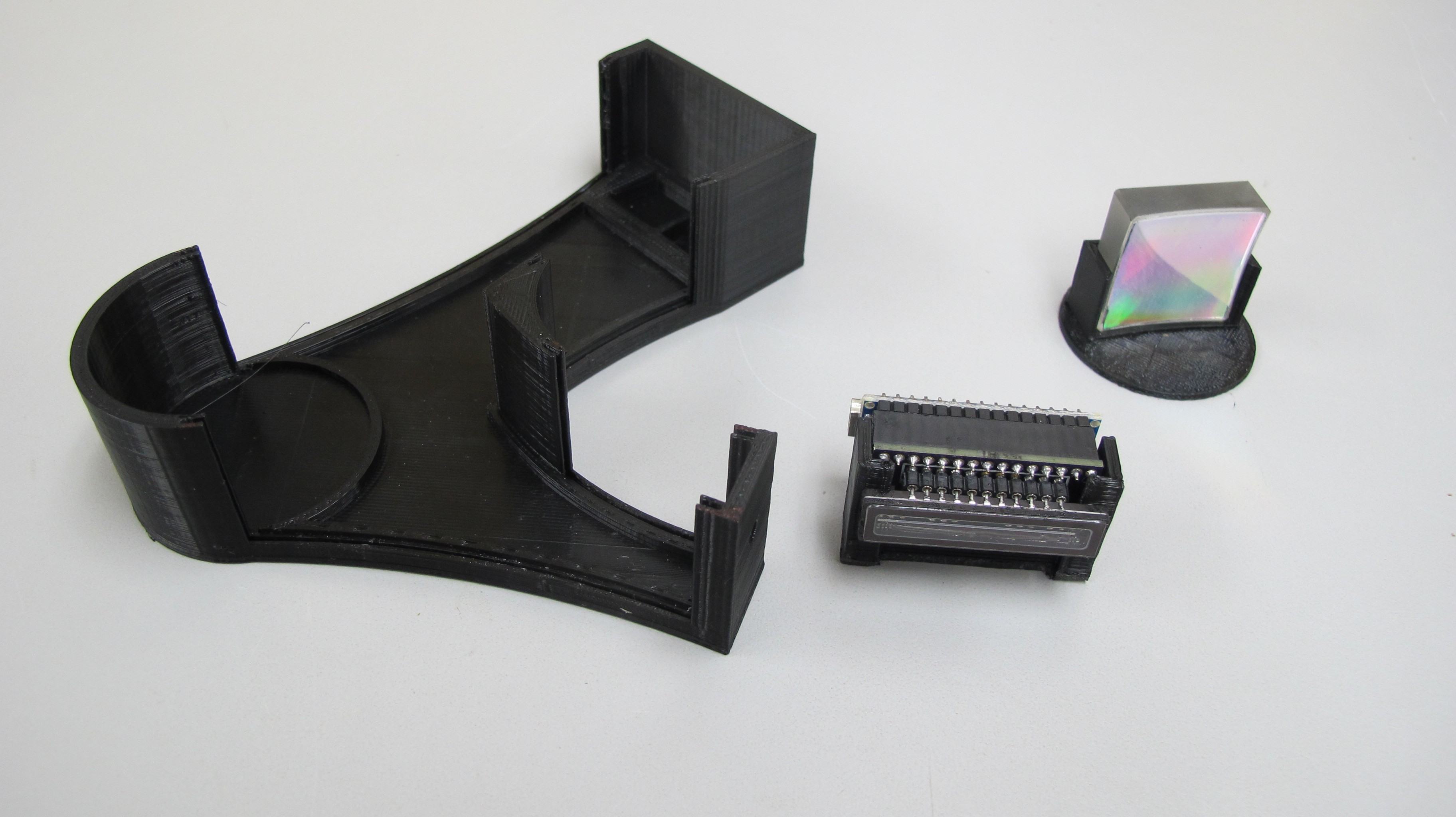
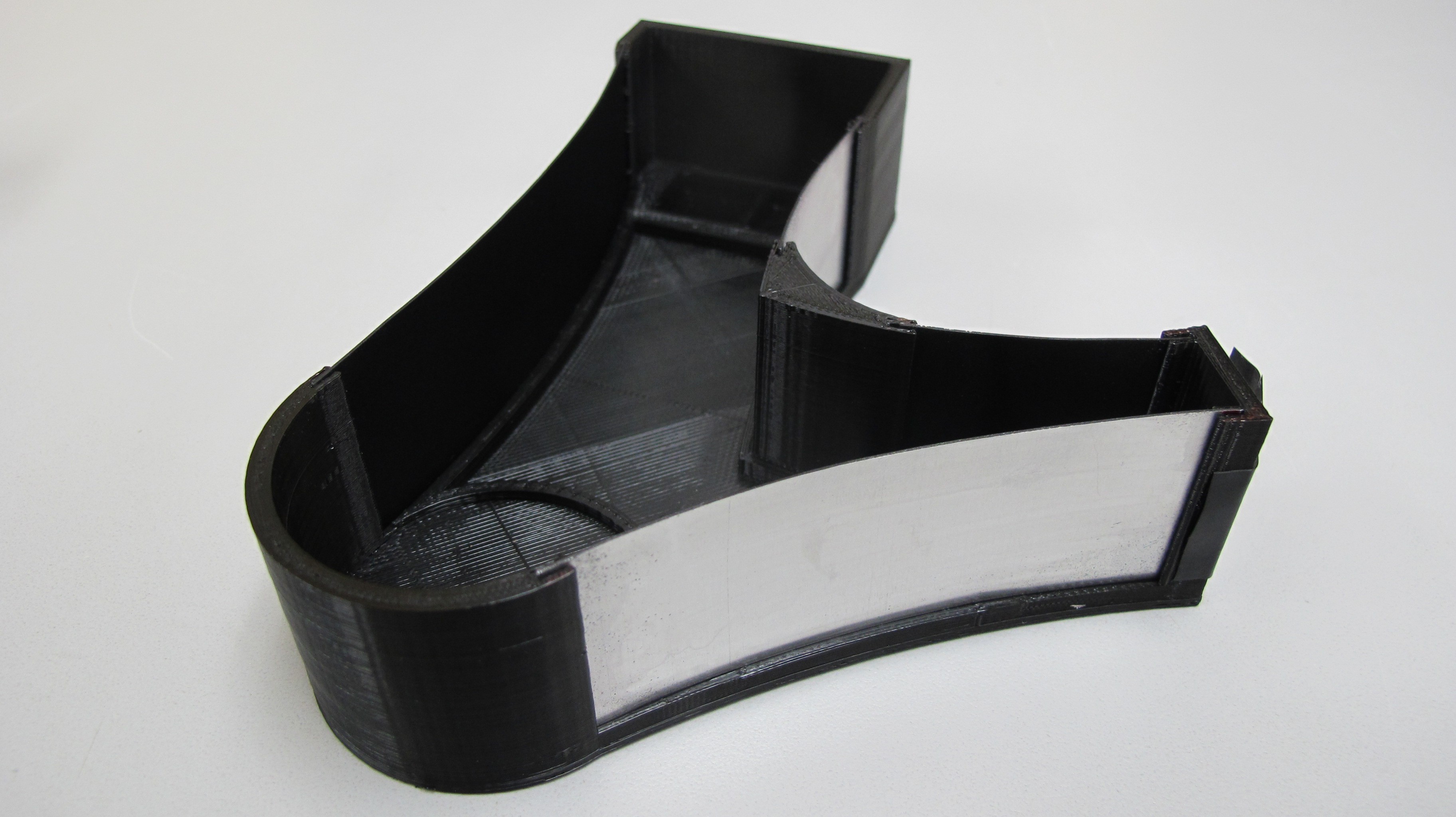
04/24/2017 at 02:57 • 2 commentsI finally got around to printing an enclosure for the spectrometer this weekend. To cut down in print time I removed most of the walls and will use aluminum sheeting instead. Depending on how that works out in the long run I may stick with it or switch to a fully plastic enclosure.
Spectrometer components. Both the grating base and the CCD hold are removable, for now. This allows me to rotate the grating to test out different configurations.
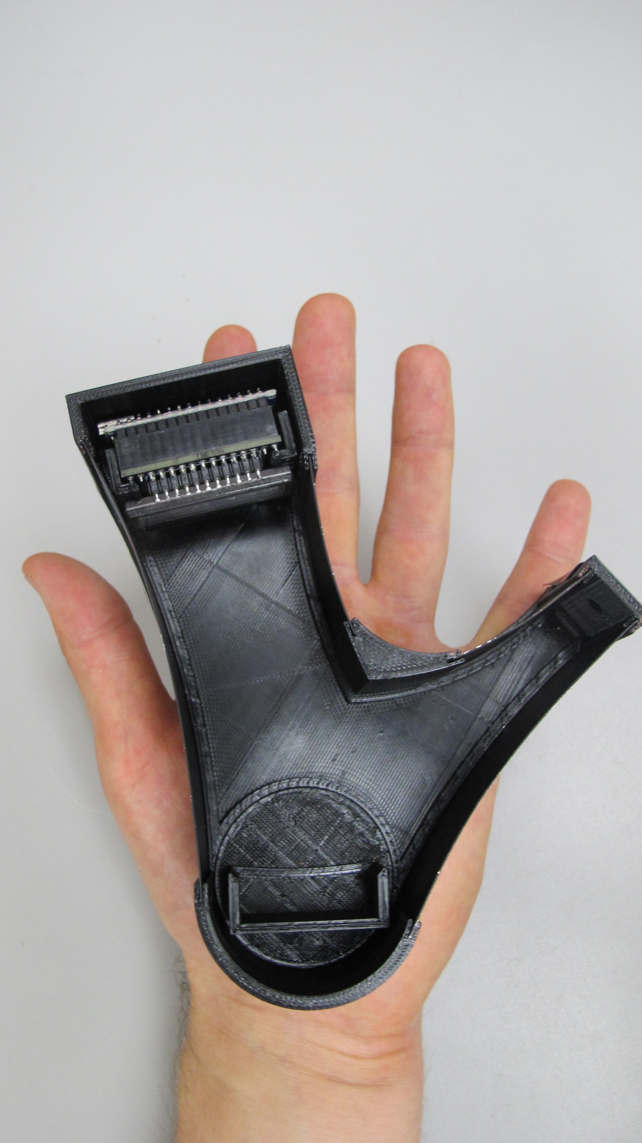
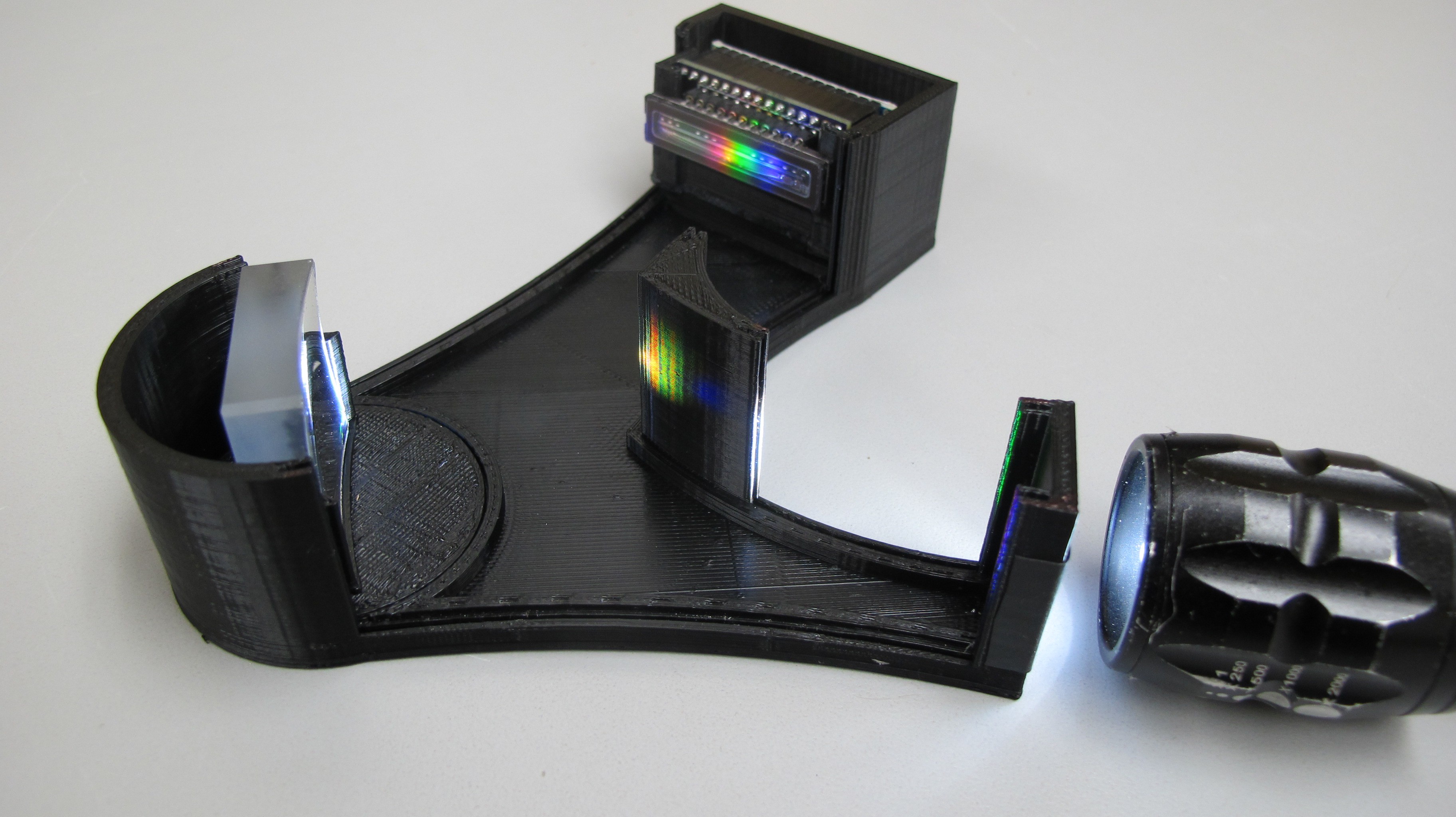
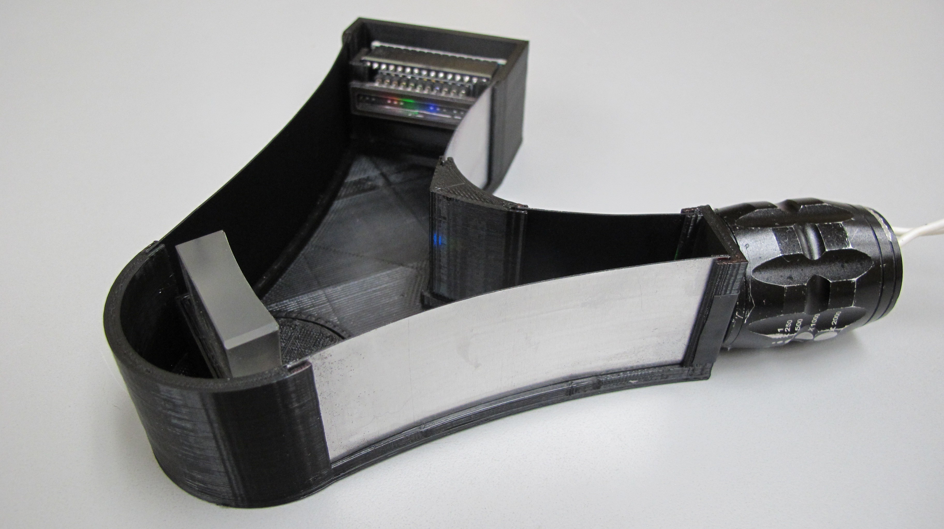
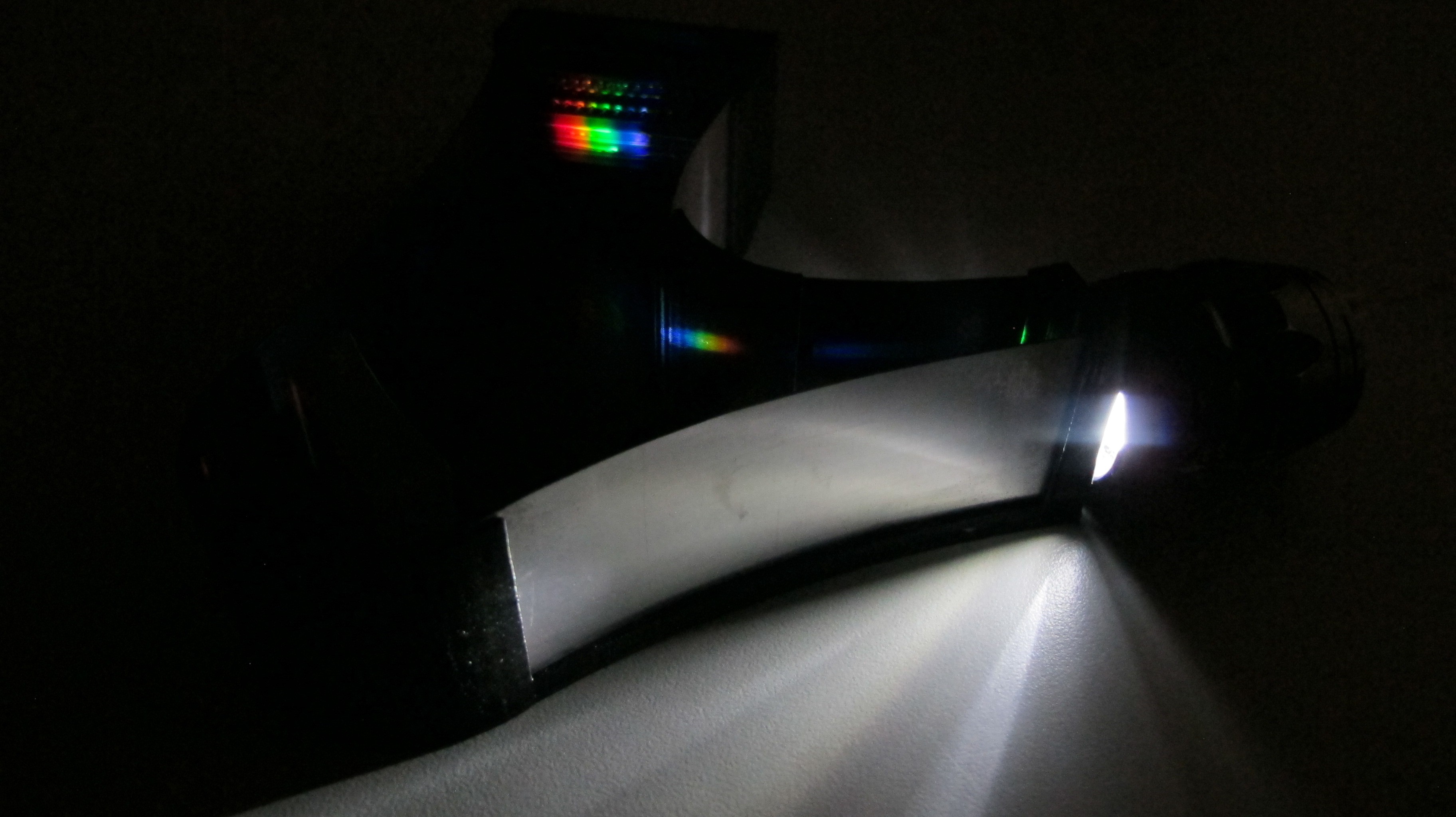
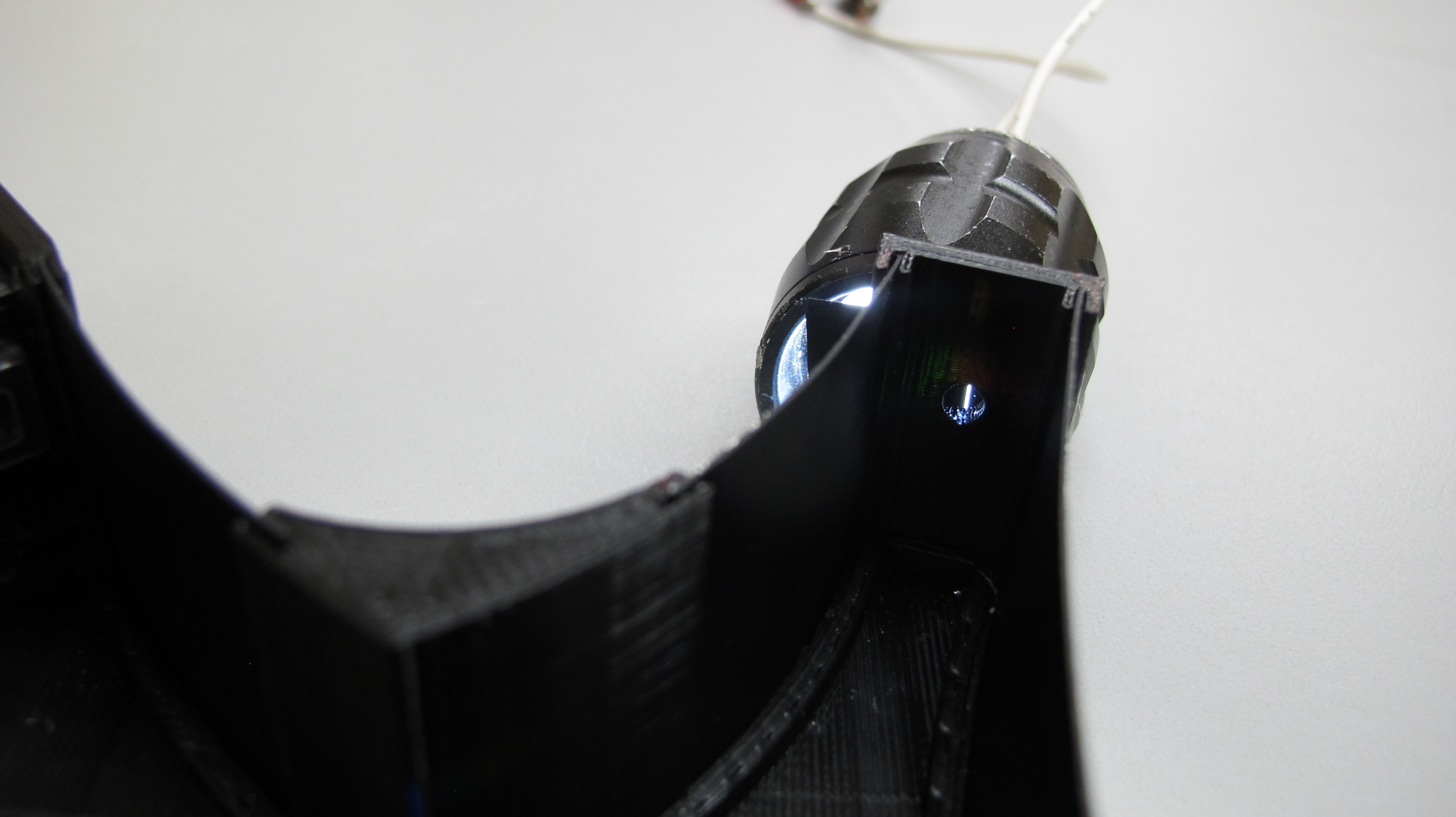
Hand for scale, its more handheld now than before. I plan on cutting down on the footprint in future versions by changing the placement of the CCD circuit and fixing the grating holder in place. Right now the grating holder is on a rotating circular base to allow for adjustments.Grating, slit and CCD installed and illuminated with and LED flashlight.
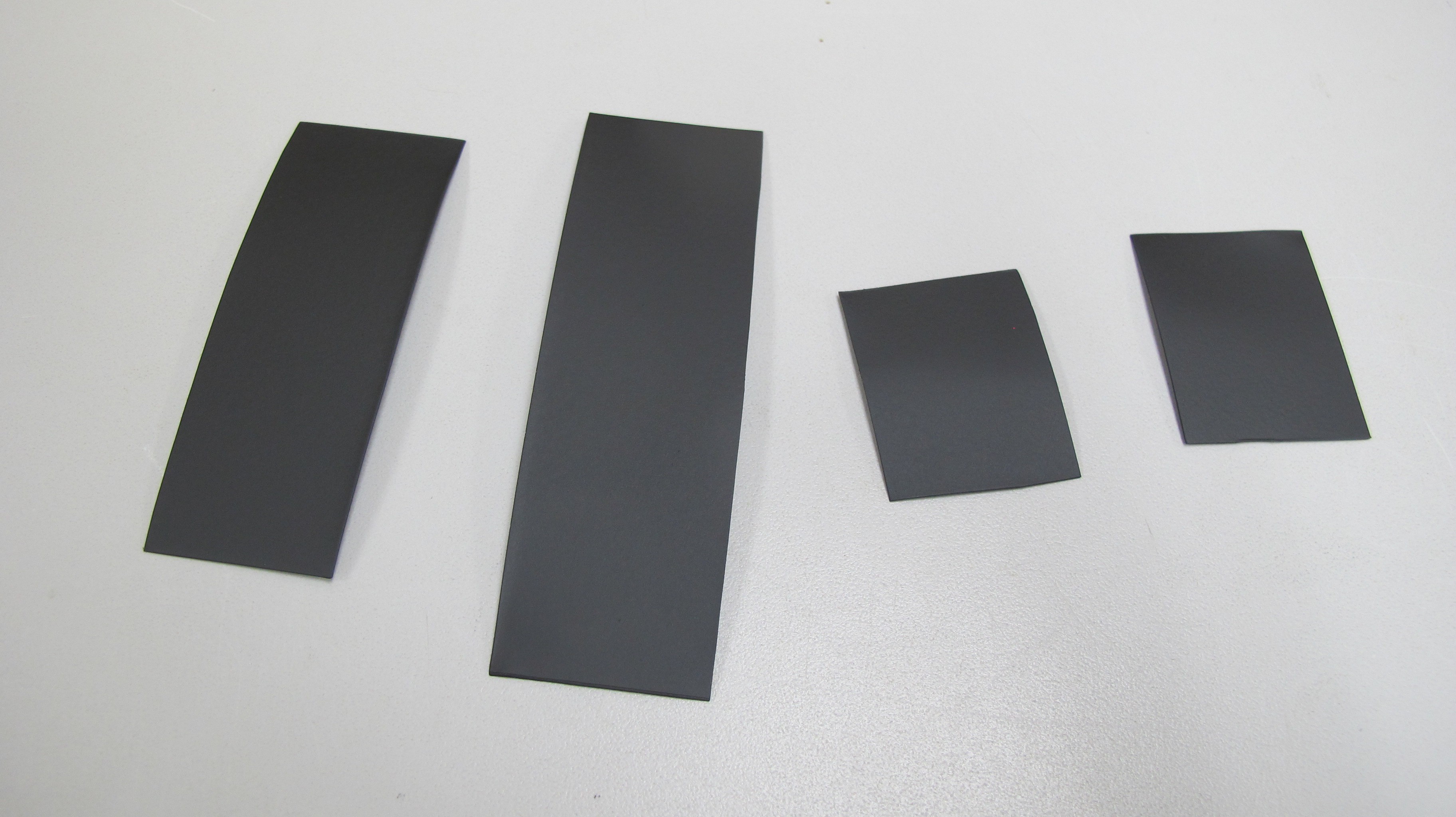
Spectrometer walls. I cut these out of ~0.5mm aluminum sheeting and spray painted them black.
Enclosure with walls installed.
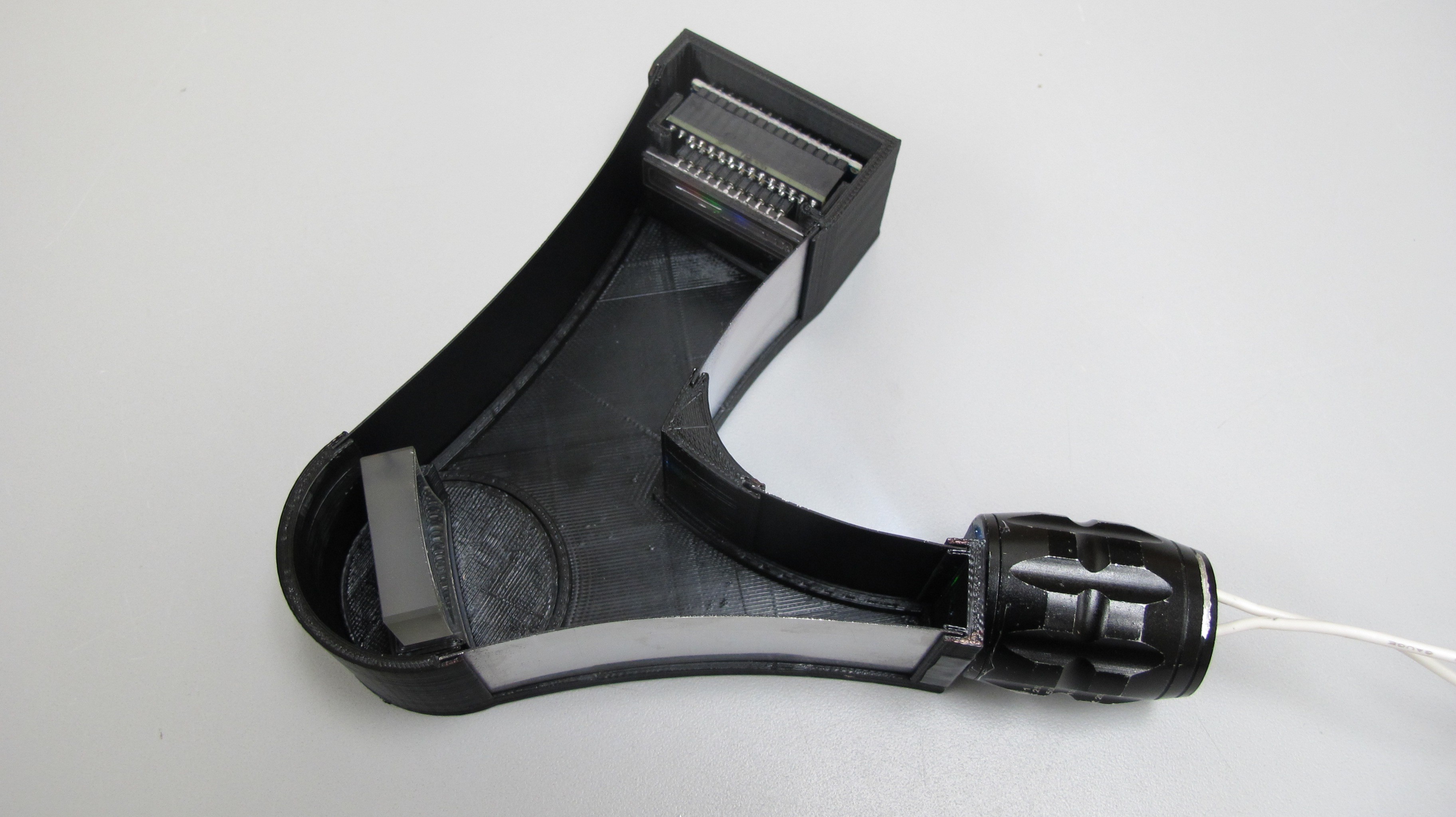
Assembled spectrometer, sans cover.
Next up I need to design a cover and drill a hole to allow for USB connection to the CCD controller.
-
CCD
07/22/2016 at 01:15 • 0 commentsCCD Board Evolution
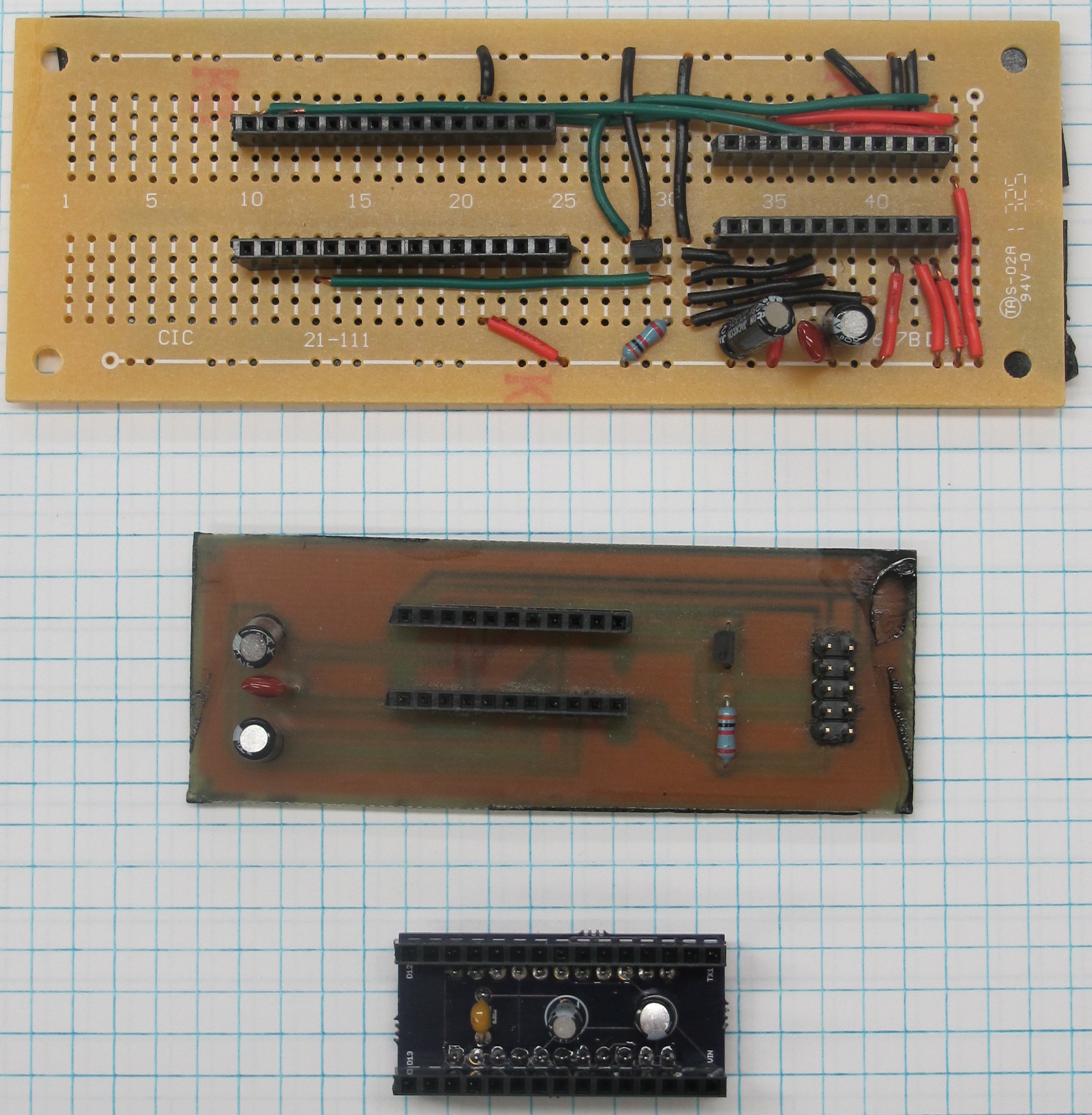
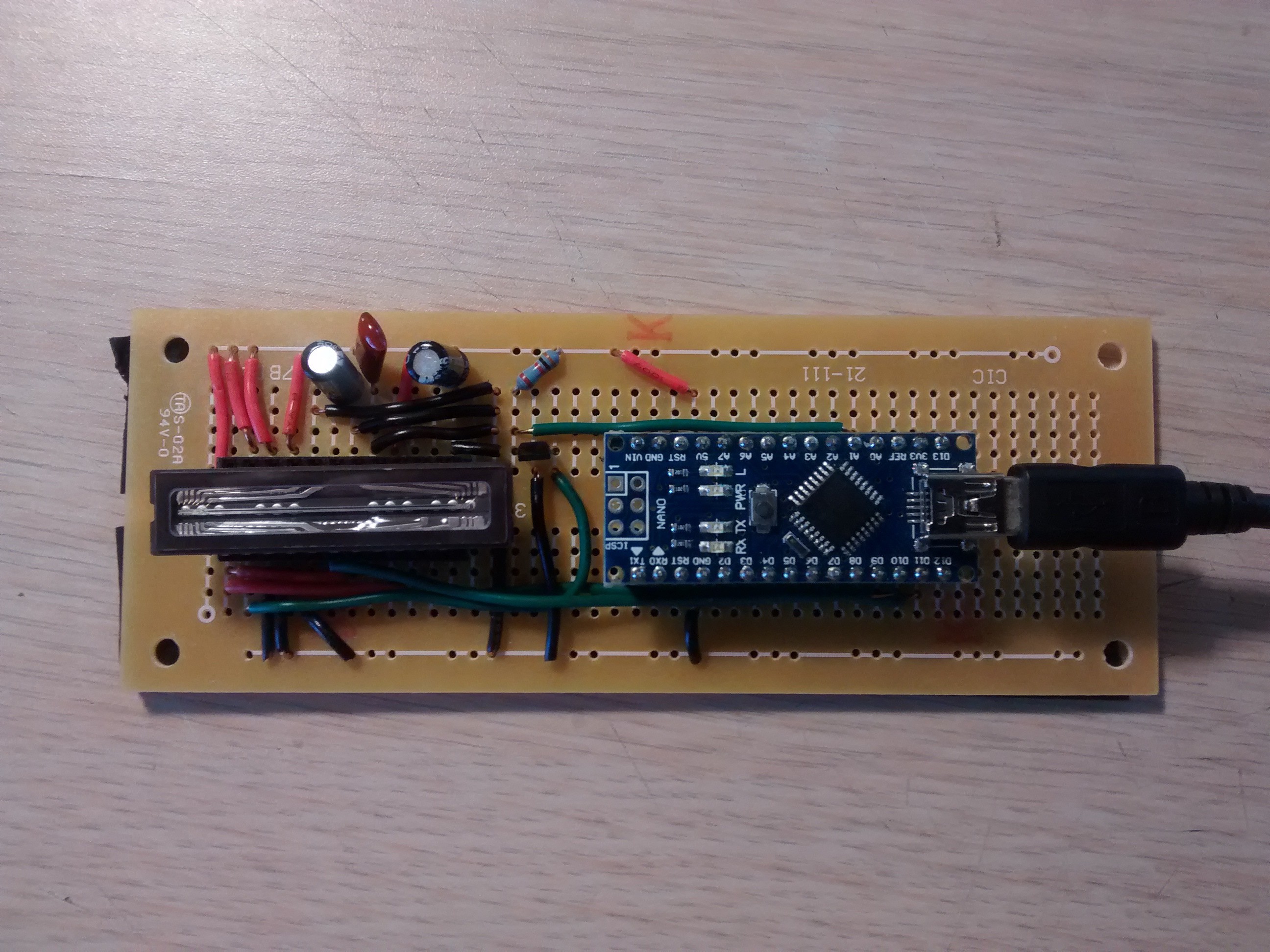
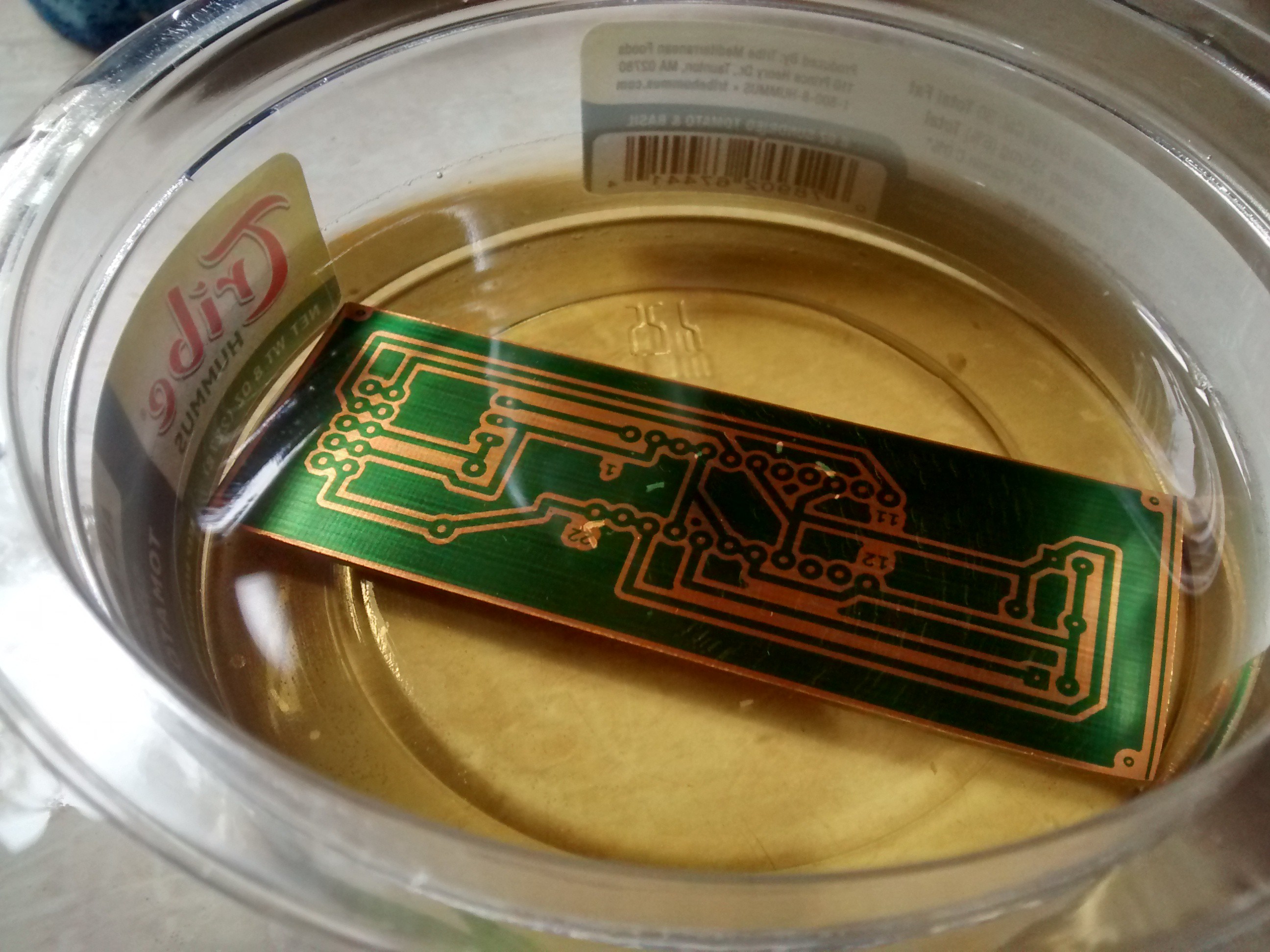
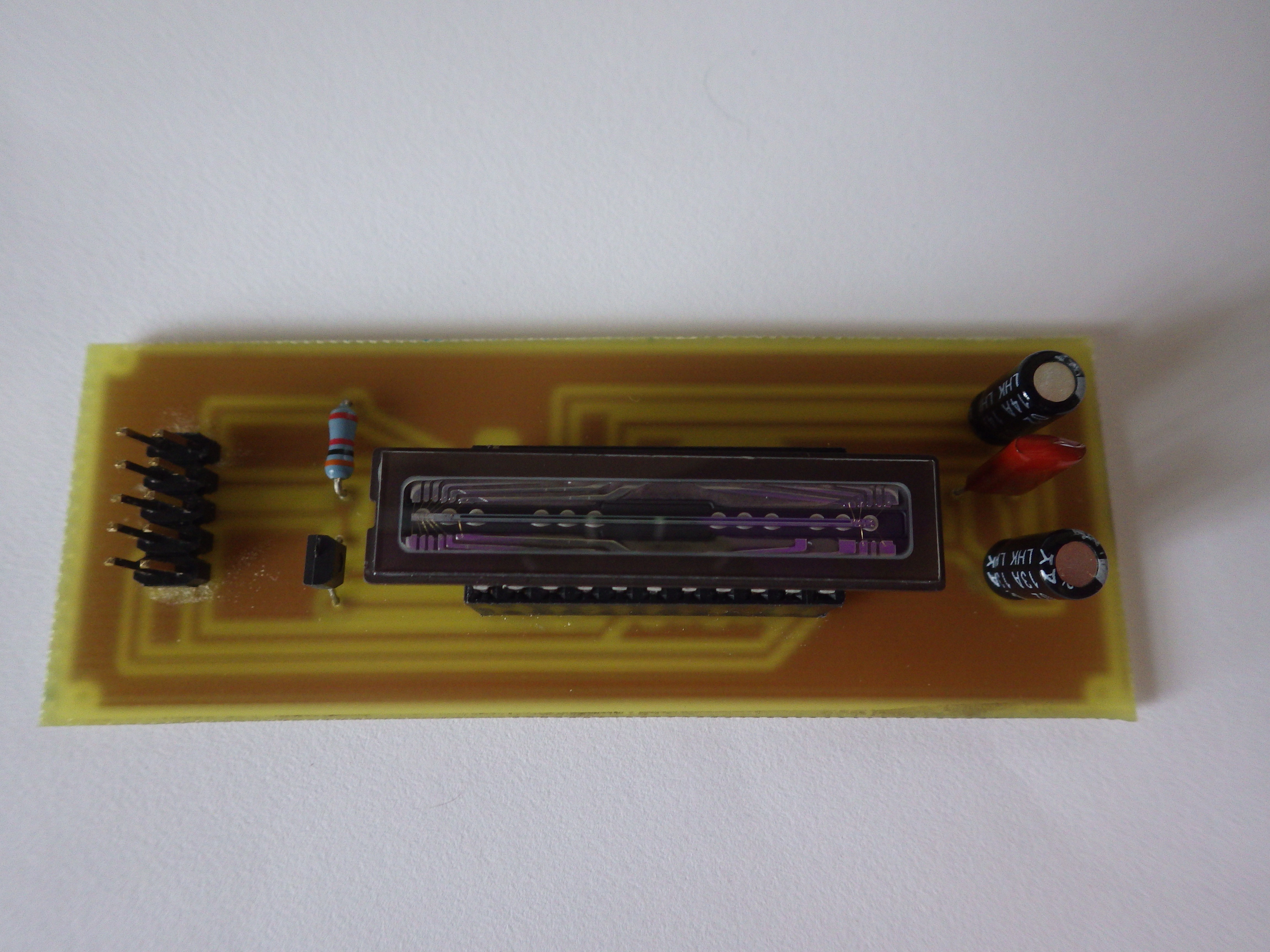
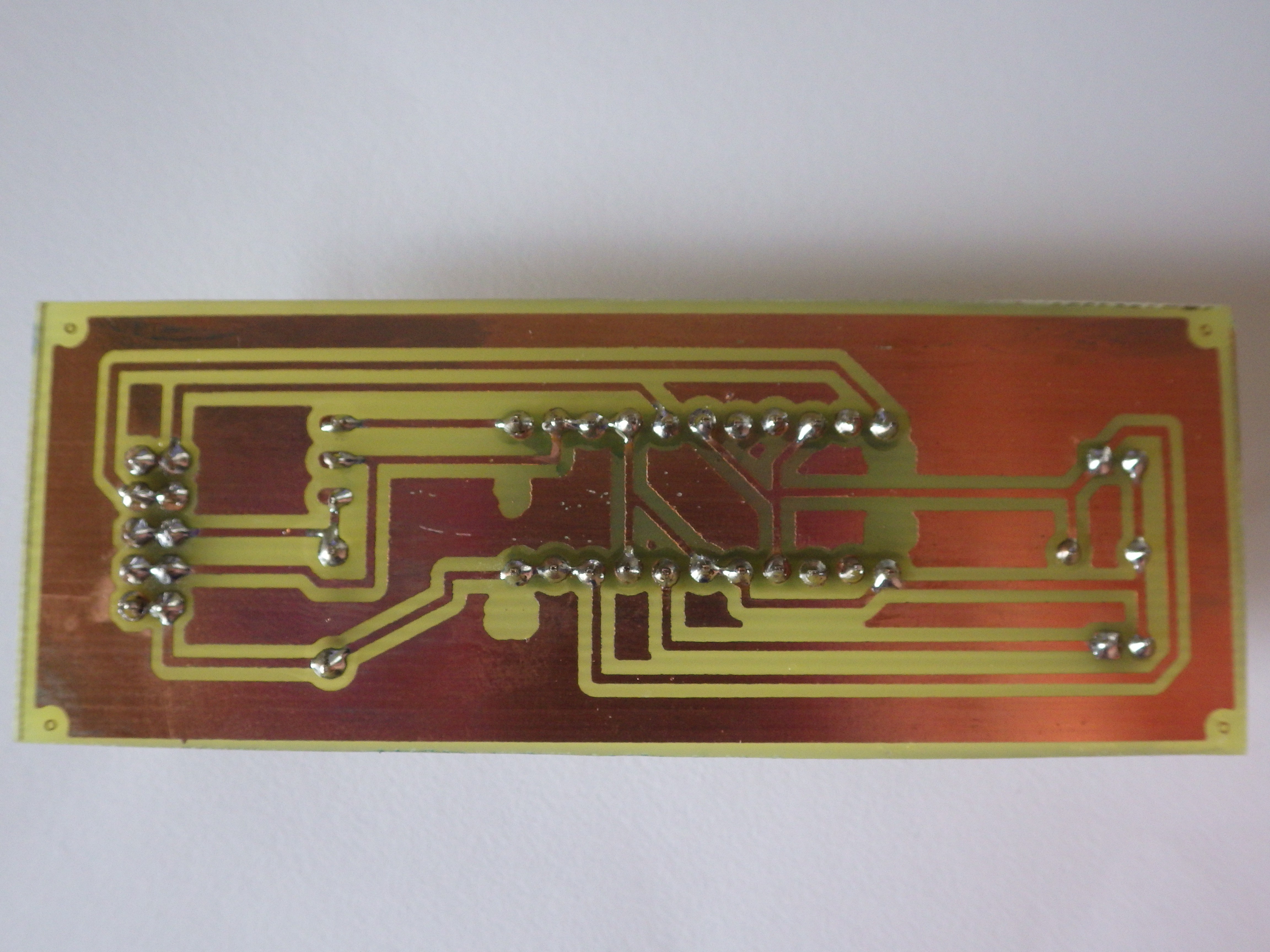
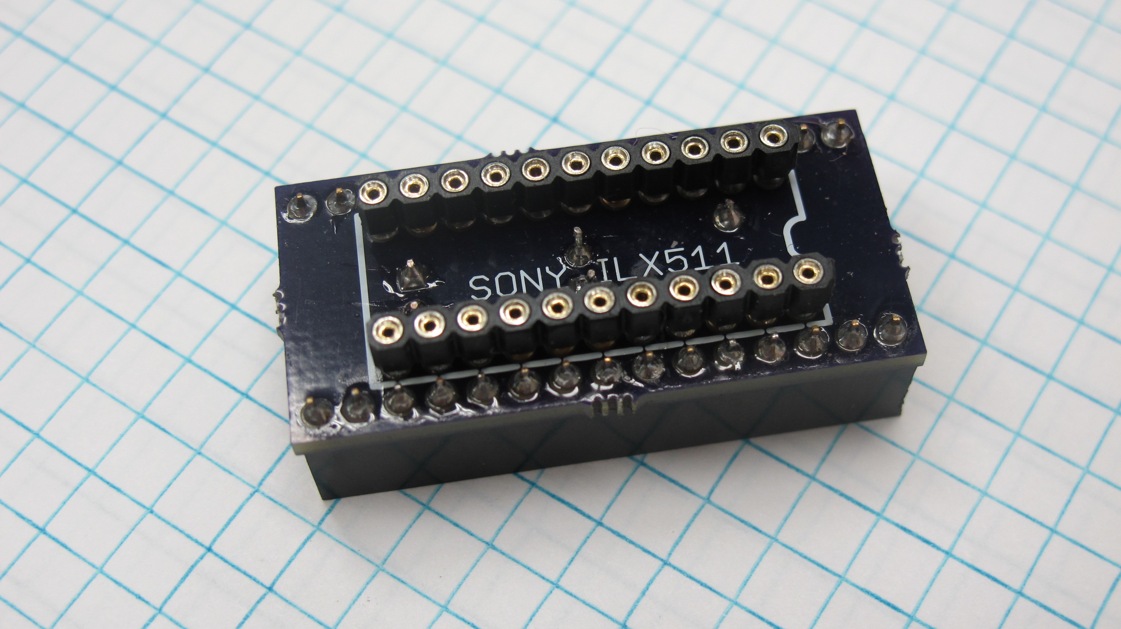
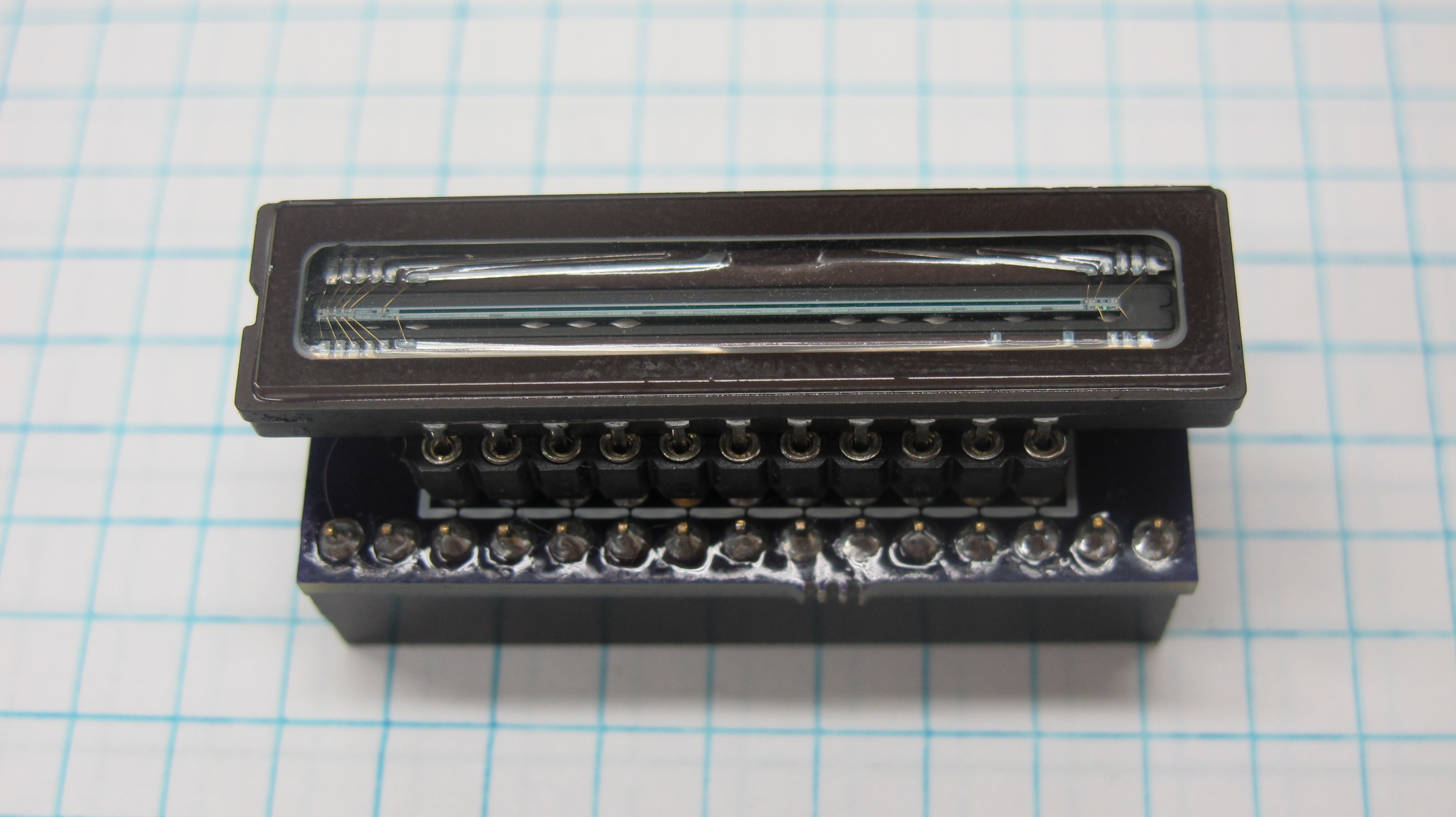
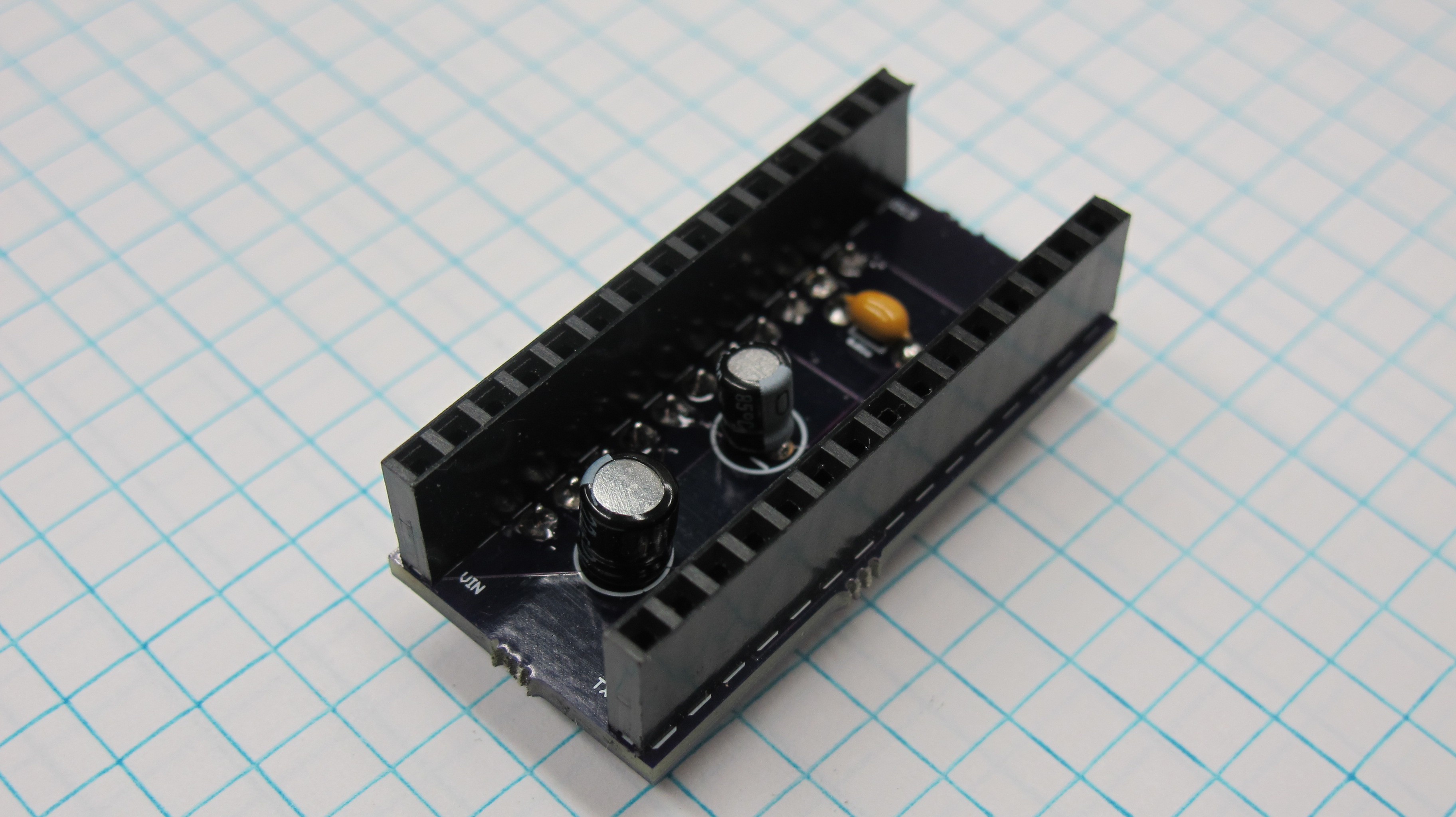
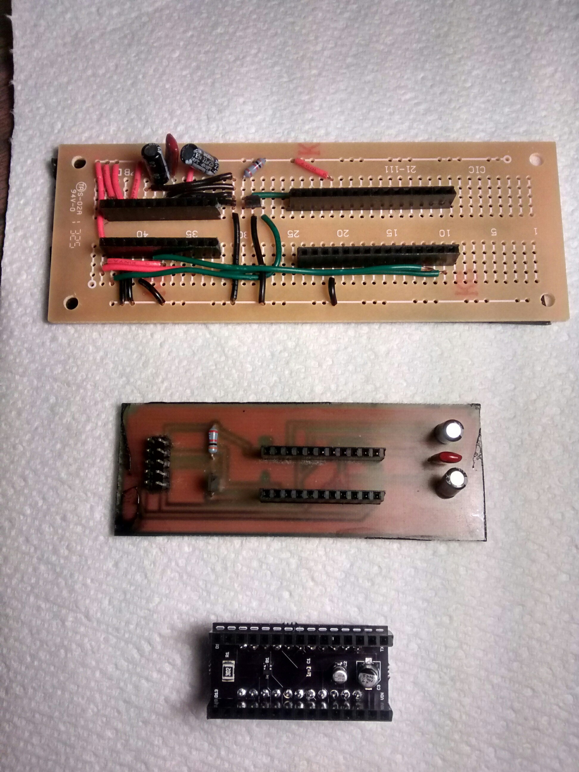
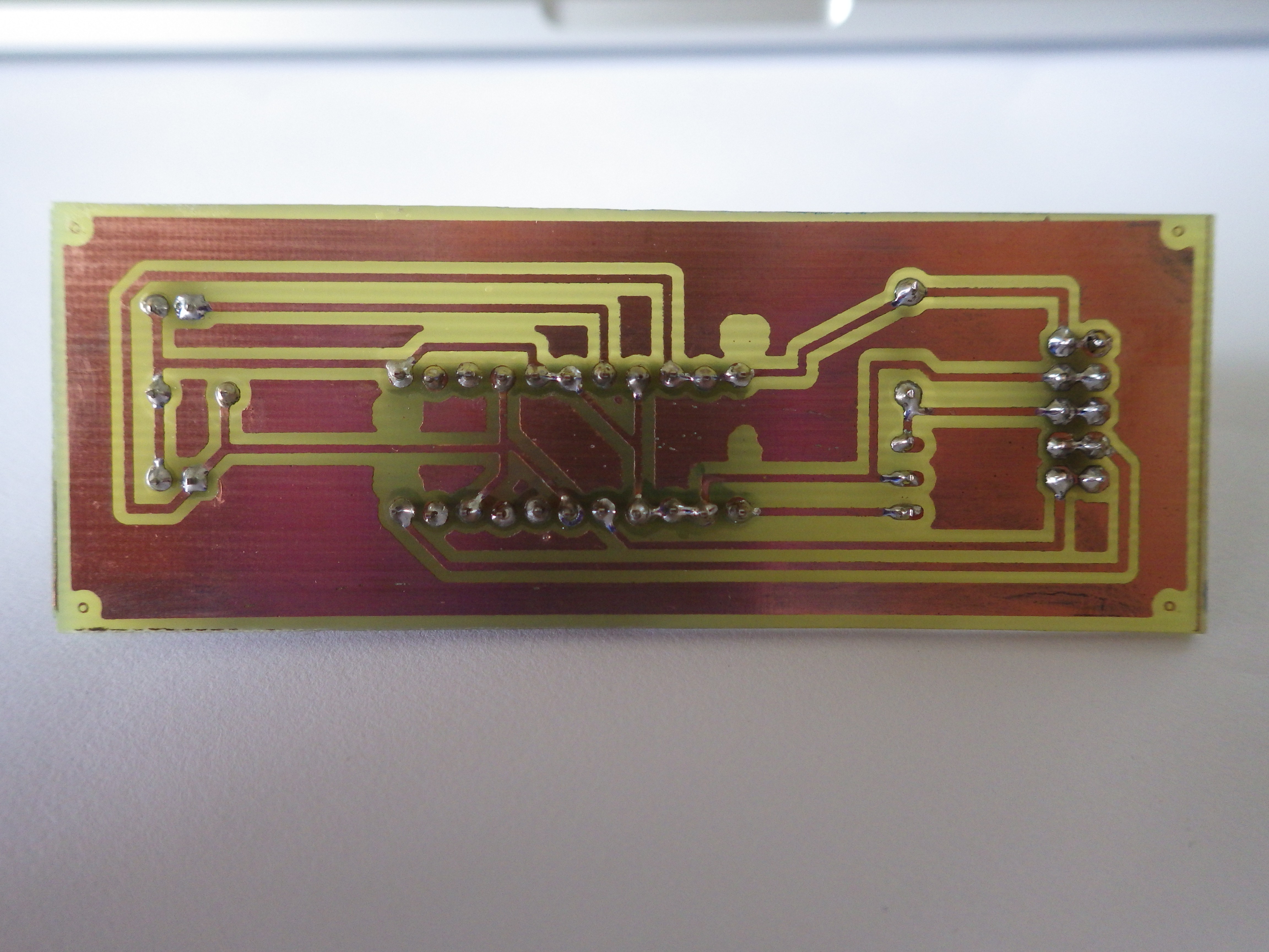
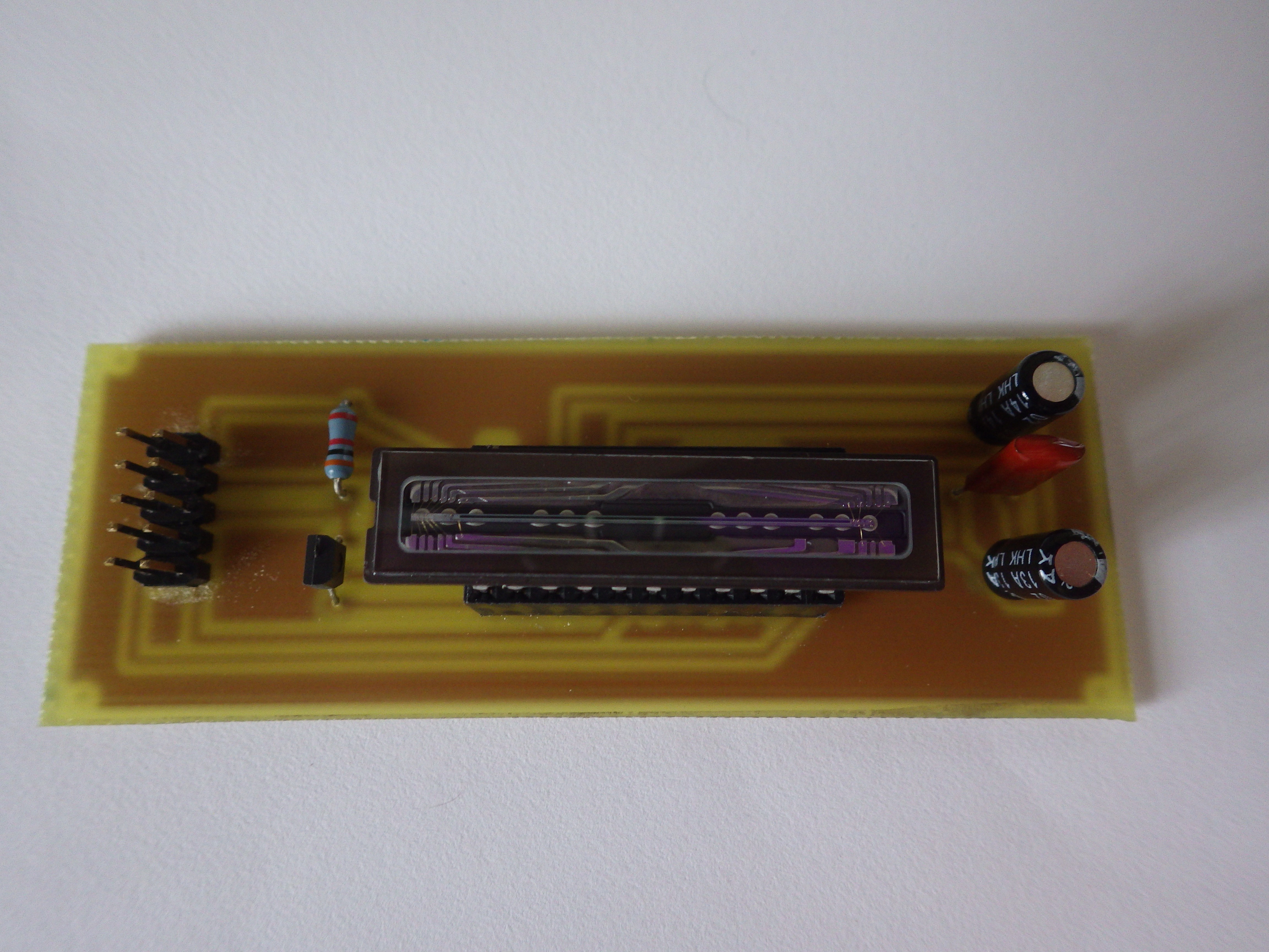
The picture below shows the evolution of the CCD controller board from perf board to etched PCB to OSH Park PCB.
Perf Board
![]()
Etched PCB
Etching in progress..........
![]()
OSH Park PCB
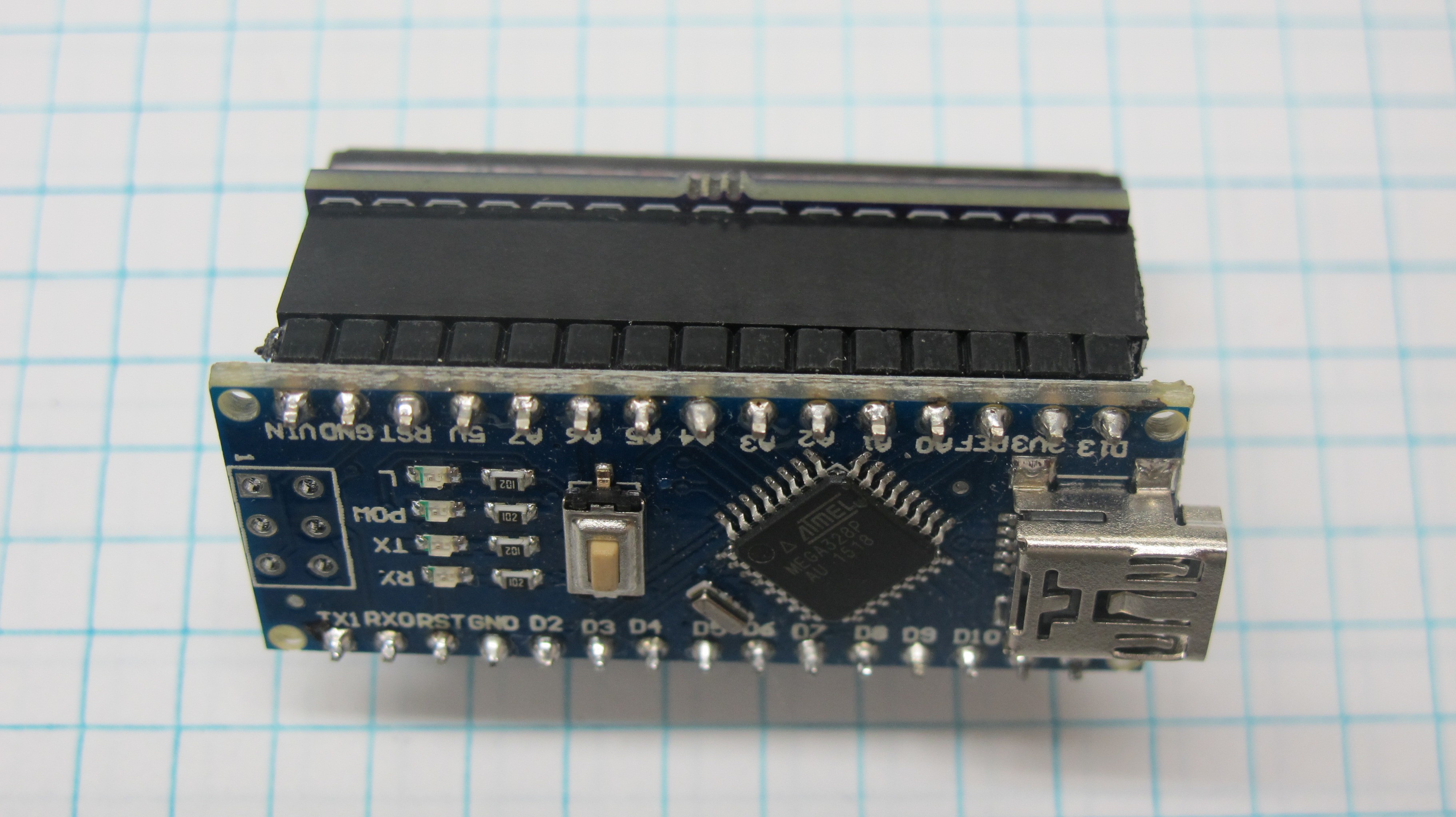
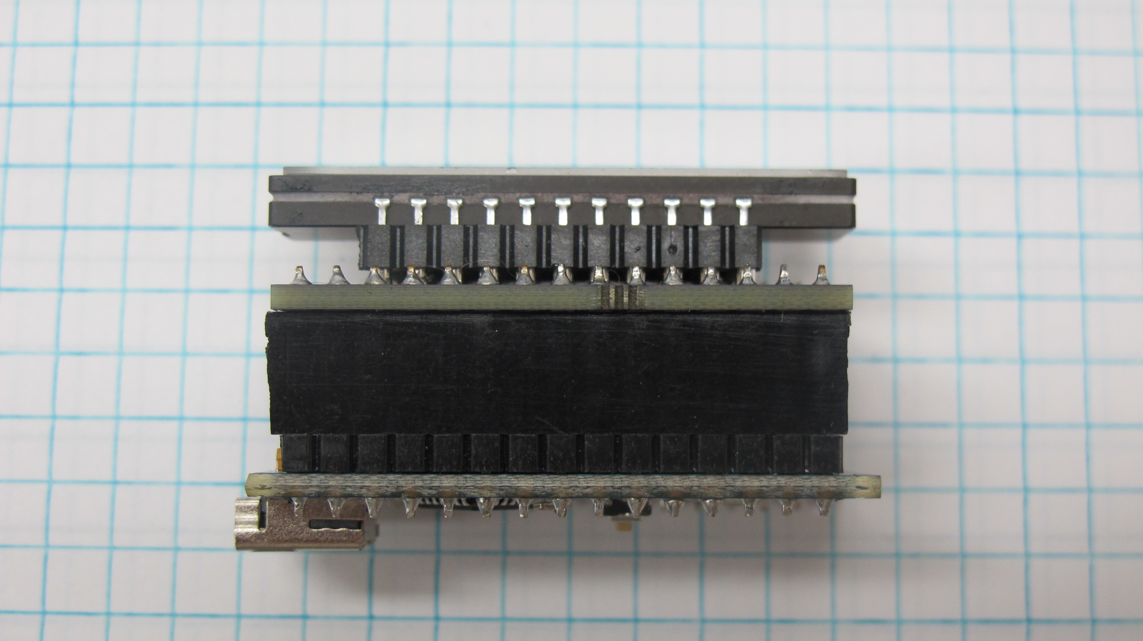
While the etched board was nice because it reduced the size of the board compared to the perf board design it still was too large for my design. So I went ahead and designed a CCD shield for the Arduino nano and sent the design off to OSH Park to get made. Initially I had designed the board with SMDs, however after multiple attempts and redesigns I was not able to get the board working. I went back to the drawing board and redesigned it using through hole components like the etched board, and had success. I also figured that it would be easier to other to replicate my design with through hole components rather than SMDs.
As you can see from the picture I used two different type of header for the shield, for the Arduino I use run of the mill square headers, however for the CCD I used round pin headers (here). I did this because I found that the square headers did not full come into contact with the CCD pins and because the round pins reduced the profile of the board a bit.
-
Enclosure
07/20/2016 at 23:45 • 0 commentsAlthough the spectrometer in its current enclosure can be held in a single hand it is not handheld in the sense that I would eventually like it to be. I envision the spectrometer being operated with one hand and the ability to view spectra in realtime and capture spectra with the press of a trigger. I'm working on modeling a prototype and hope to share it soon.
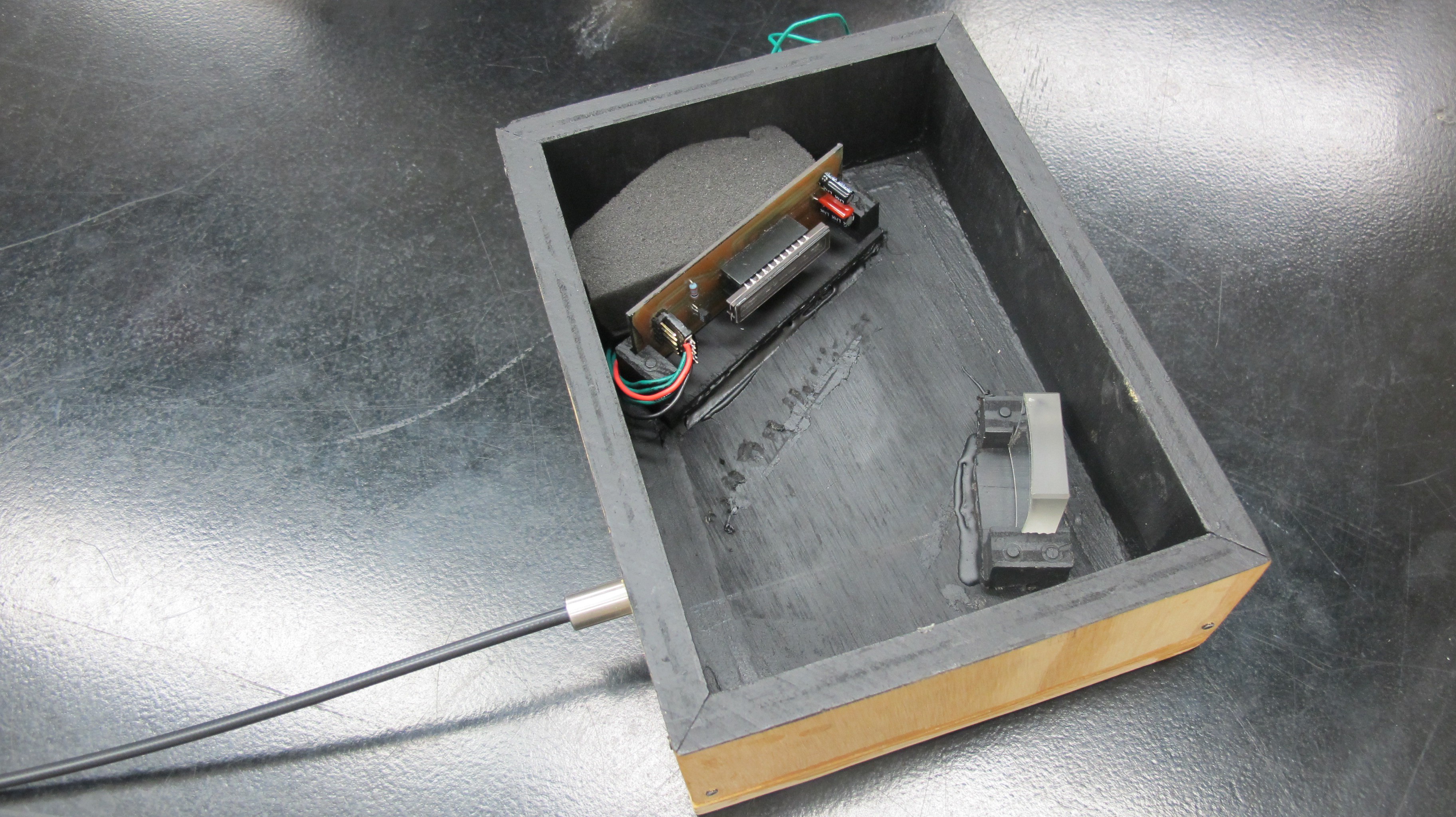
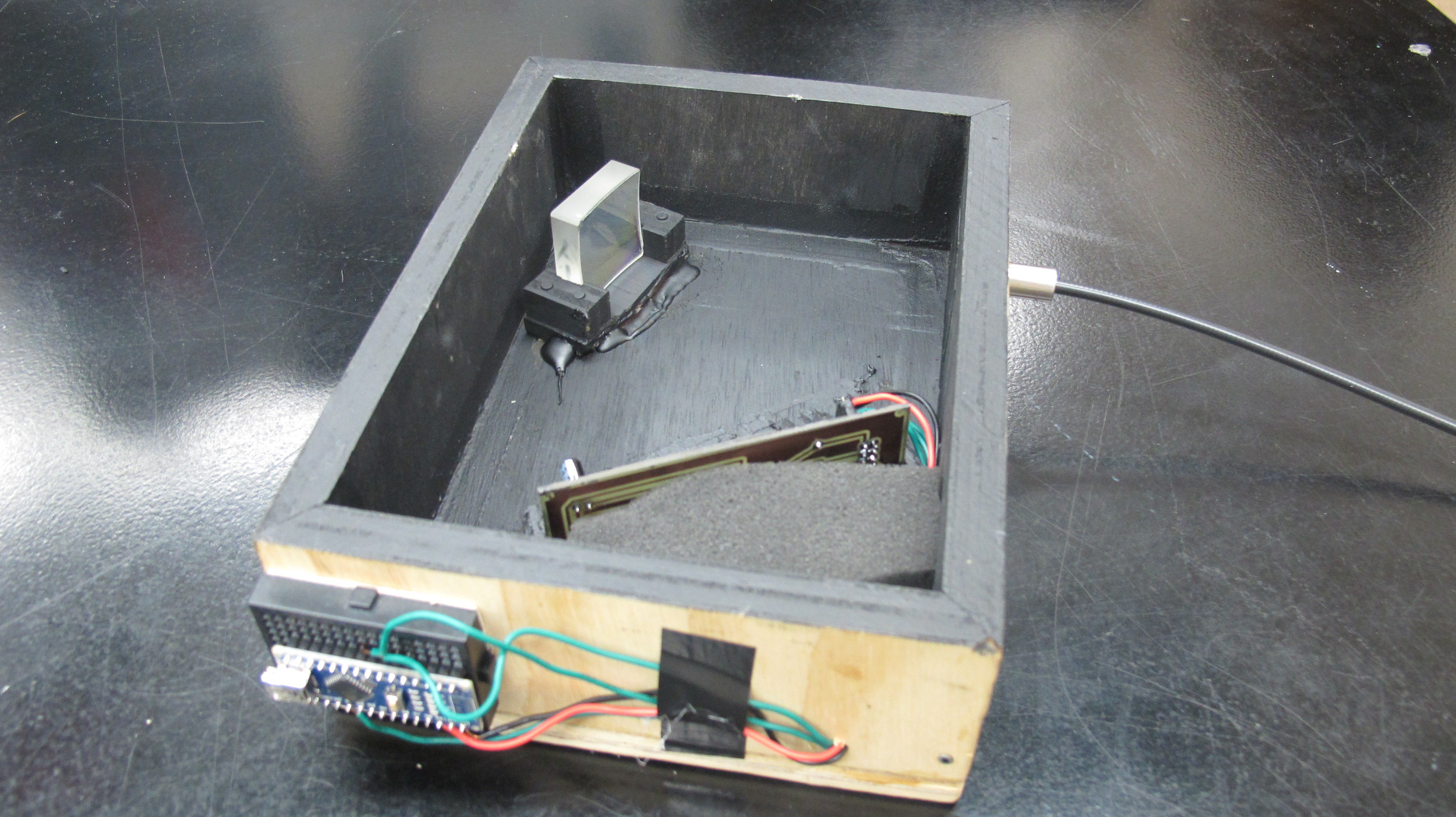
Right now the spectrometer is enclosed in a plywood box approximately 9in X 7in x 4in. The diffraction grating and CCD circuit are both held in place with wooden brackets that are hot glued to the floor of the box.
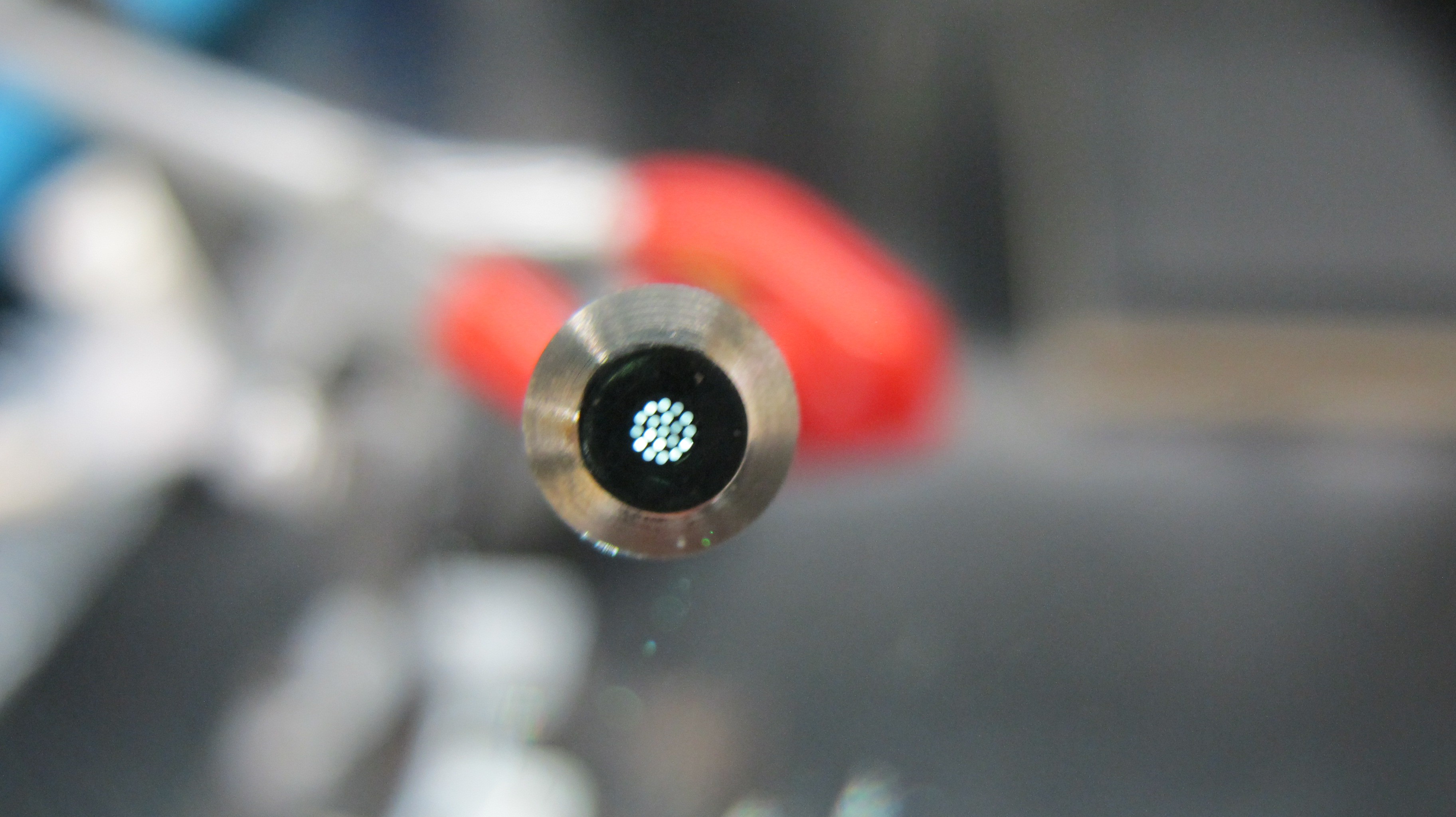
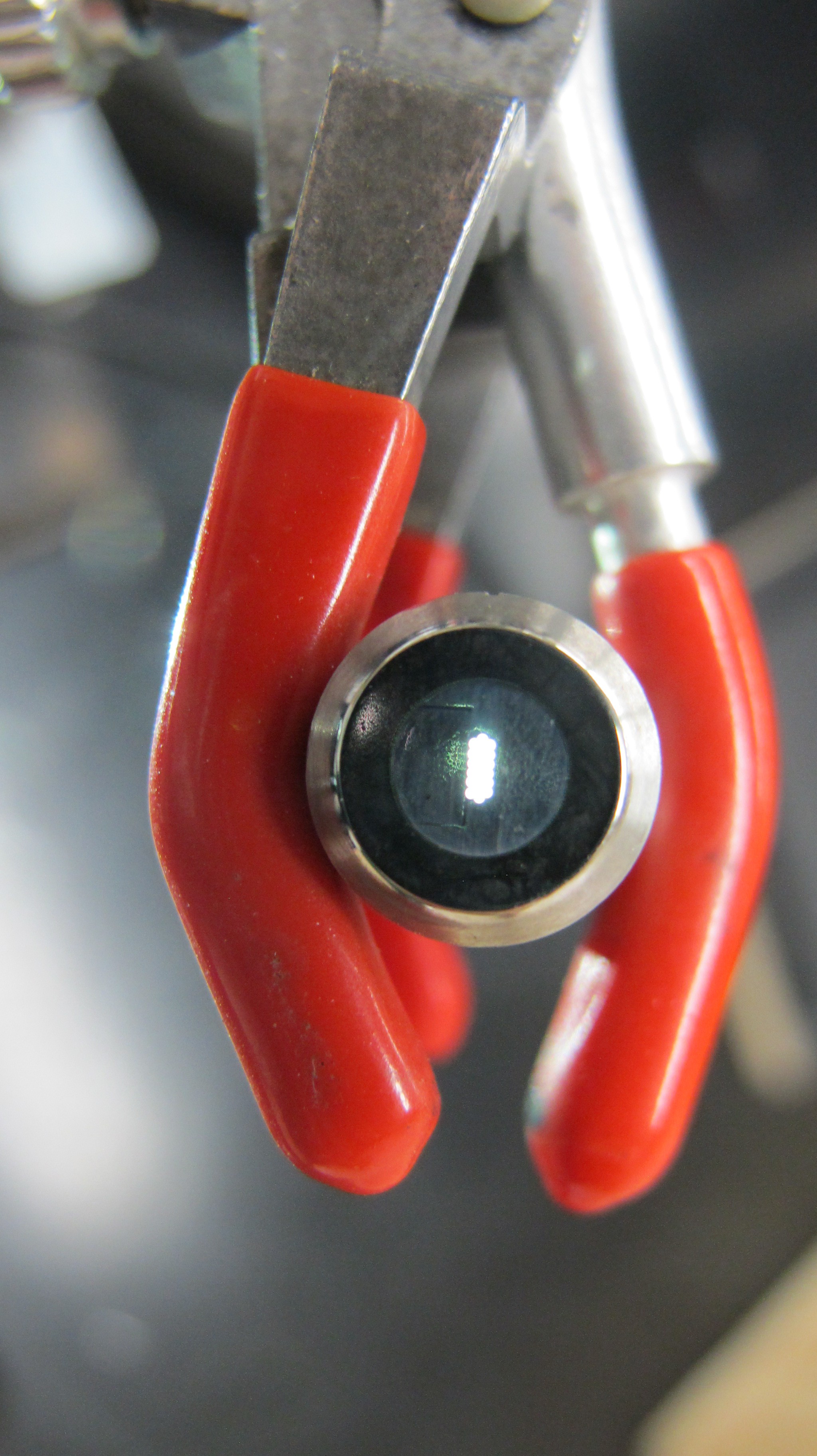
The interior of the box is spray painted black to reduce stray light reflections. However I still need to install baffles because there is still a lot of light from the higher orders diffractions that are reflected back at the CCD. I'm using a fiber optic cable I got off Ebay to shine light on the slit, this makes it easier to "look" at different things as opposed to moving the entire spectrometer.
At one end of the fiber is a circular bundle and the other end rectangular. I have the rectangular end pointing at and aligned with the slit so that more light is hitting the slit as opposed to the "walls' of the slit.
Circular bundle
Rectangular bundle
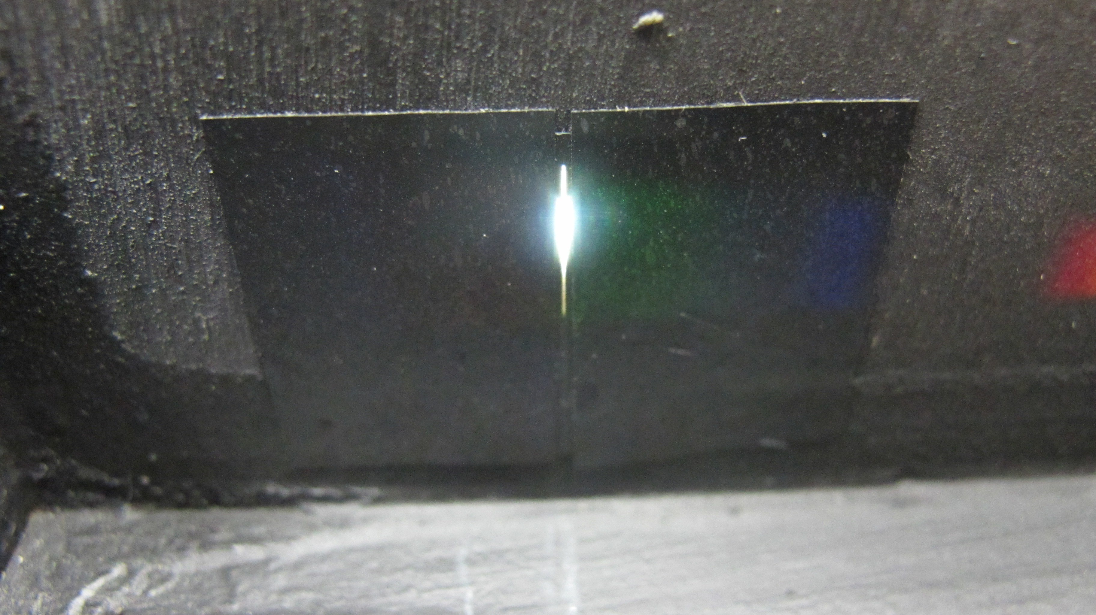
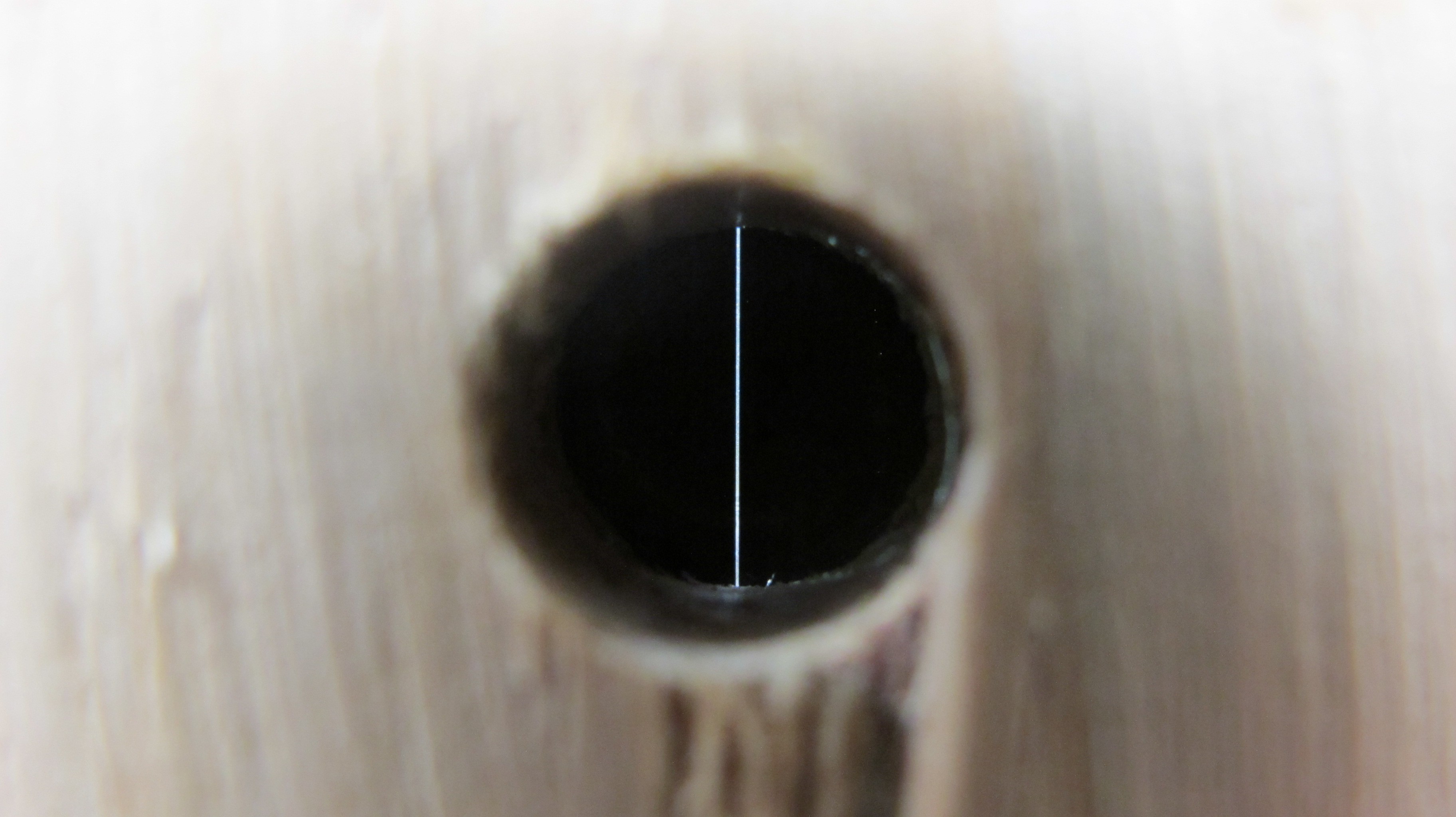
The slit I am currently used is a Public Labs actetate printed slit which I have taped to the interiror enclosure wall. For the price it works well but I found that the black ink is not completely opaque and transmits a little light. I am working on designing an adjustable slit that will eliminate this problem.
Slit from inside the spectrometer
Slit from outside the spectrometer
-
Diffraction Grating
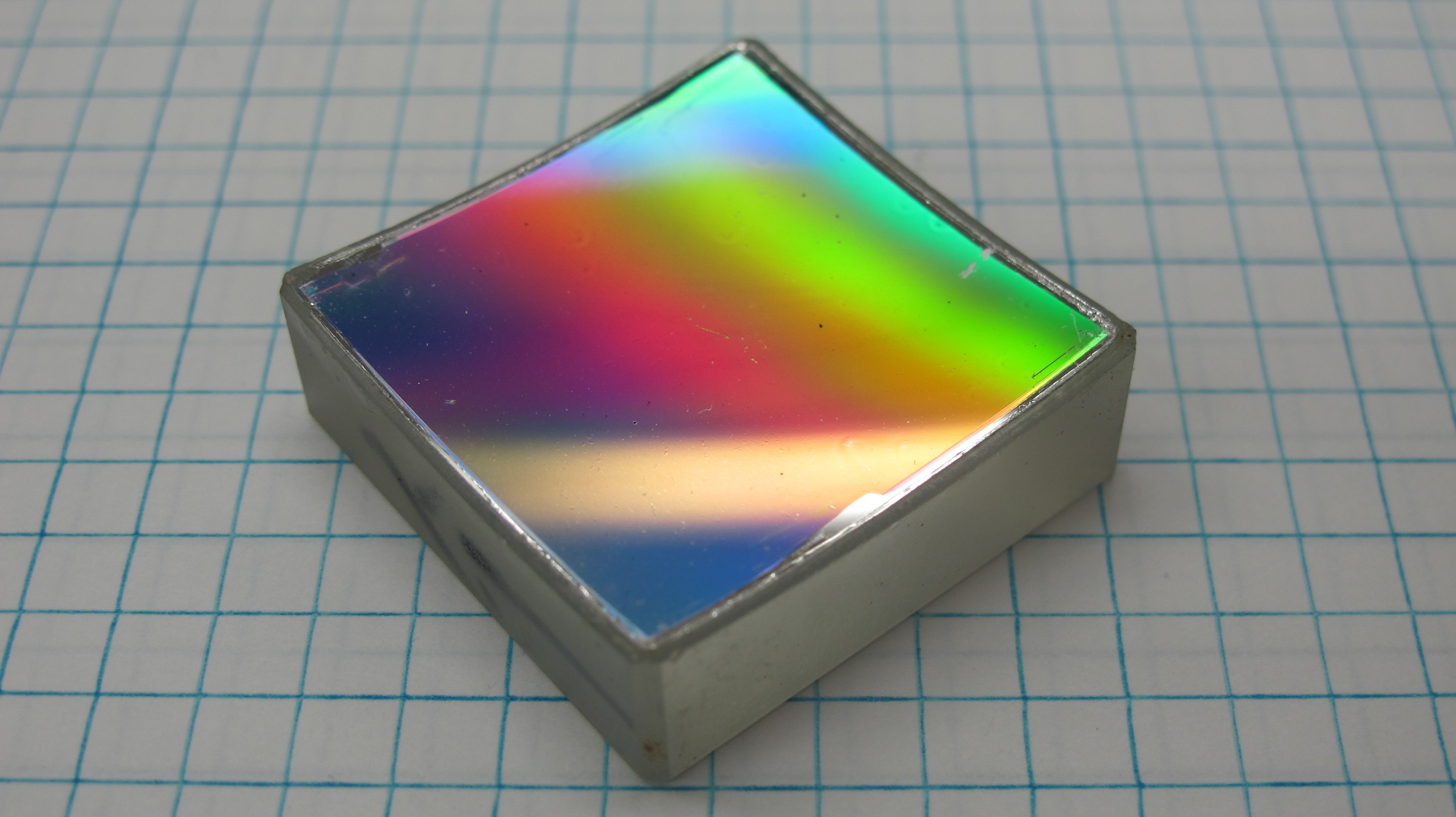
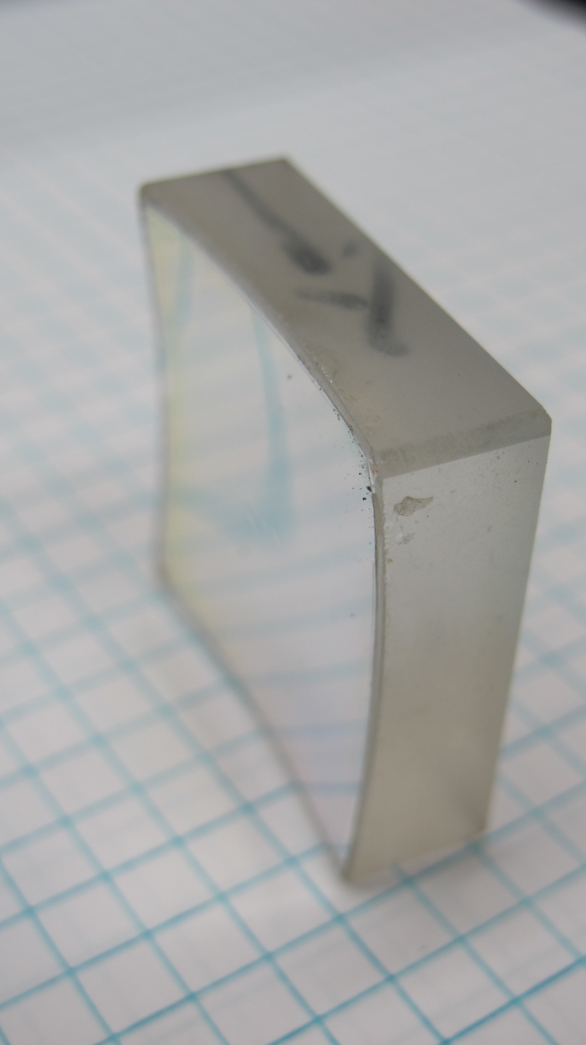
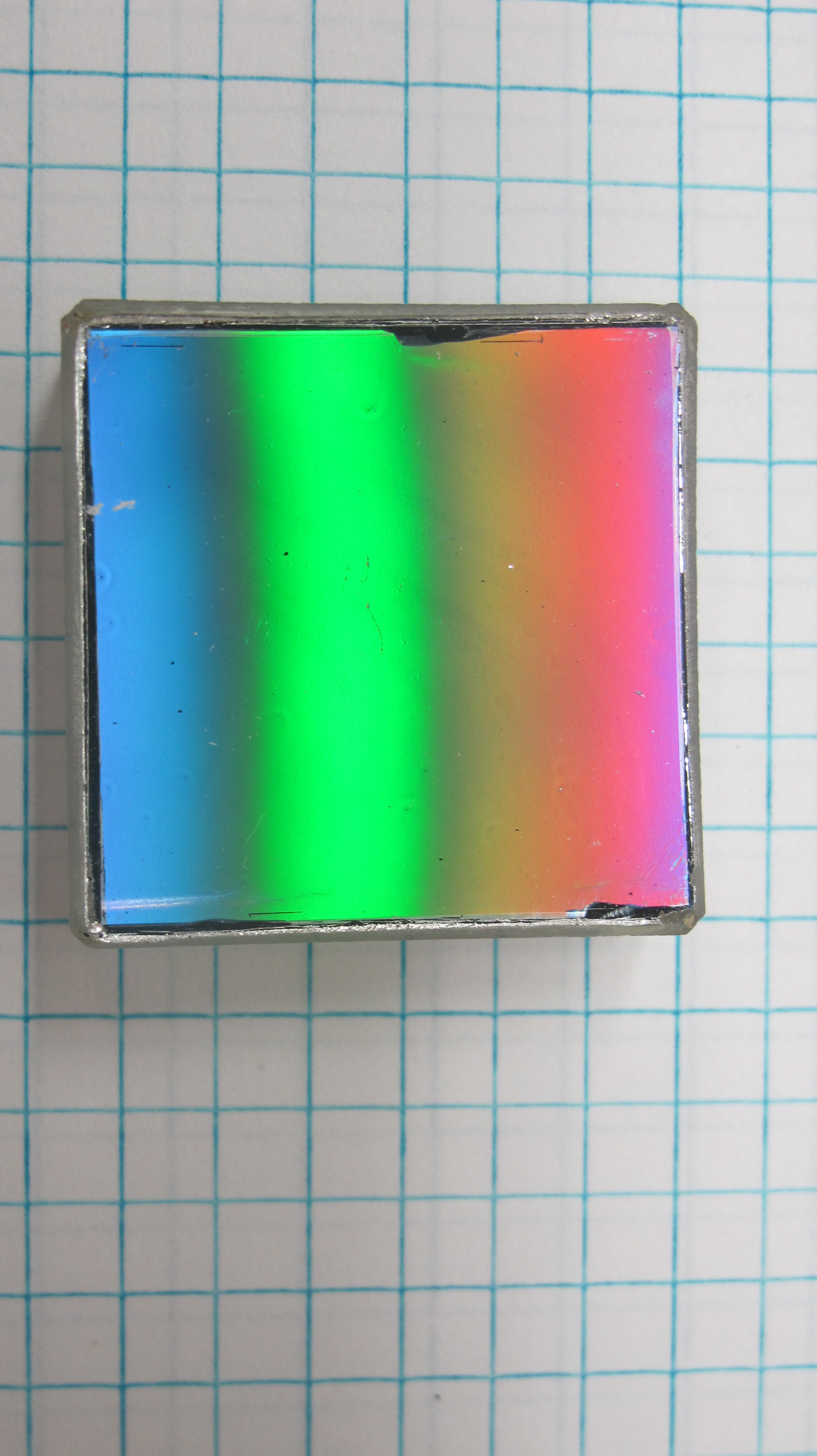
07/19/2016 at 16:01 • 0 commentsFor the diffraction grating I used a 600 l/mm holographic concave diffraction grating that I bought off of Alibaba for around $90. The concave surface of the grating serves to both collimate and focus the light eliminating the need for mirrors. This grating was design for use in a monochromator, measuring a single wavelength at a time using an exit slit, where the grating would be rotated about its central axis to change the wavelength of light impinging on the exit slit. However I found it does a fine job as a polychromator even though it is not flat field corrected.
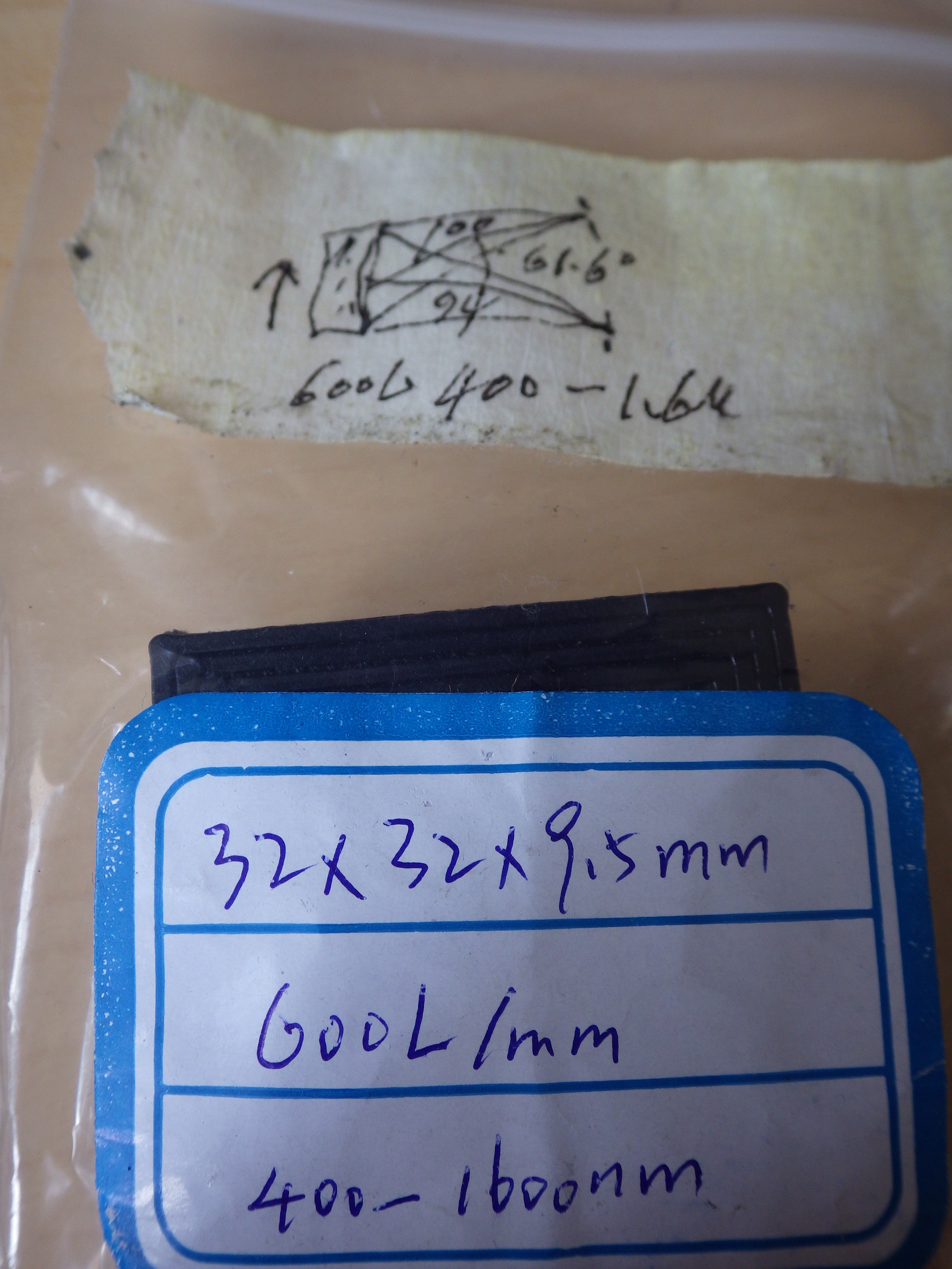
Below you can see the highly detailed technical drawing and specs that came with the grating describing it's optical properties.
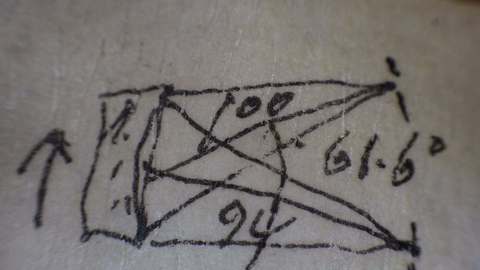
Zooming in on the drawing scribbled on the masking tape is the proper setup for the entrance and exits slits and the angle between them.
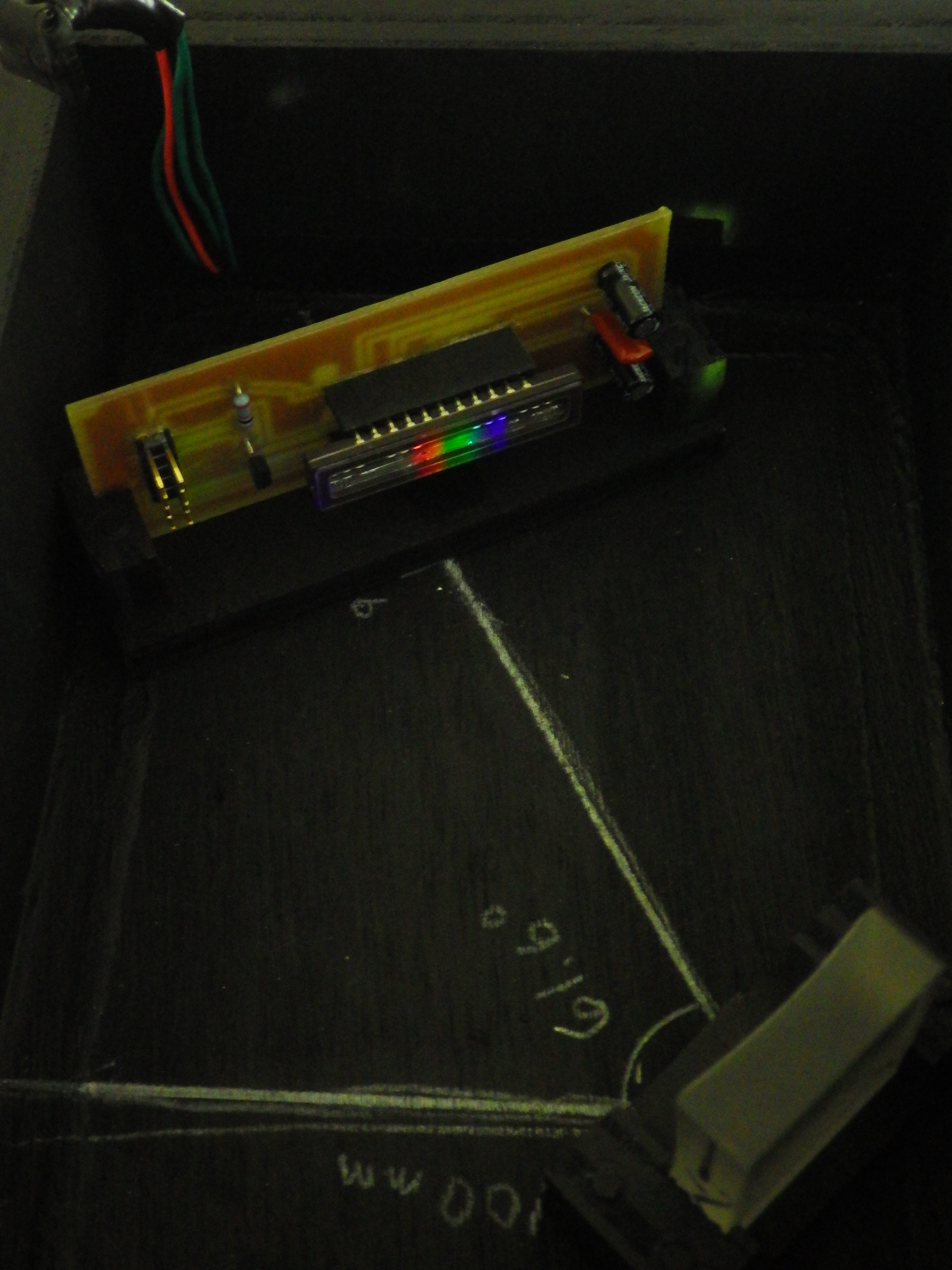
From what I can decipher, the entrance slit should be placed 94mm from the center axis of the grating while the exit slit, or in my case the CCD, should be placed 100mm from the grating at a 61.6 angle from the entrance slit arm.As you can see from the images below the surface of the grating isn't in perfect condition, but it still does the job.
-
Pictures
07/16/2016 at 22:58 • 0 commentsThis log is just a bunch of pictures with short descriptions.
Spectrometer in wooden box enclosure.
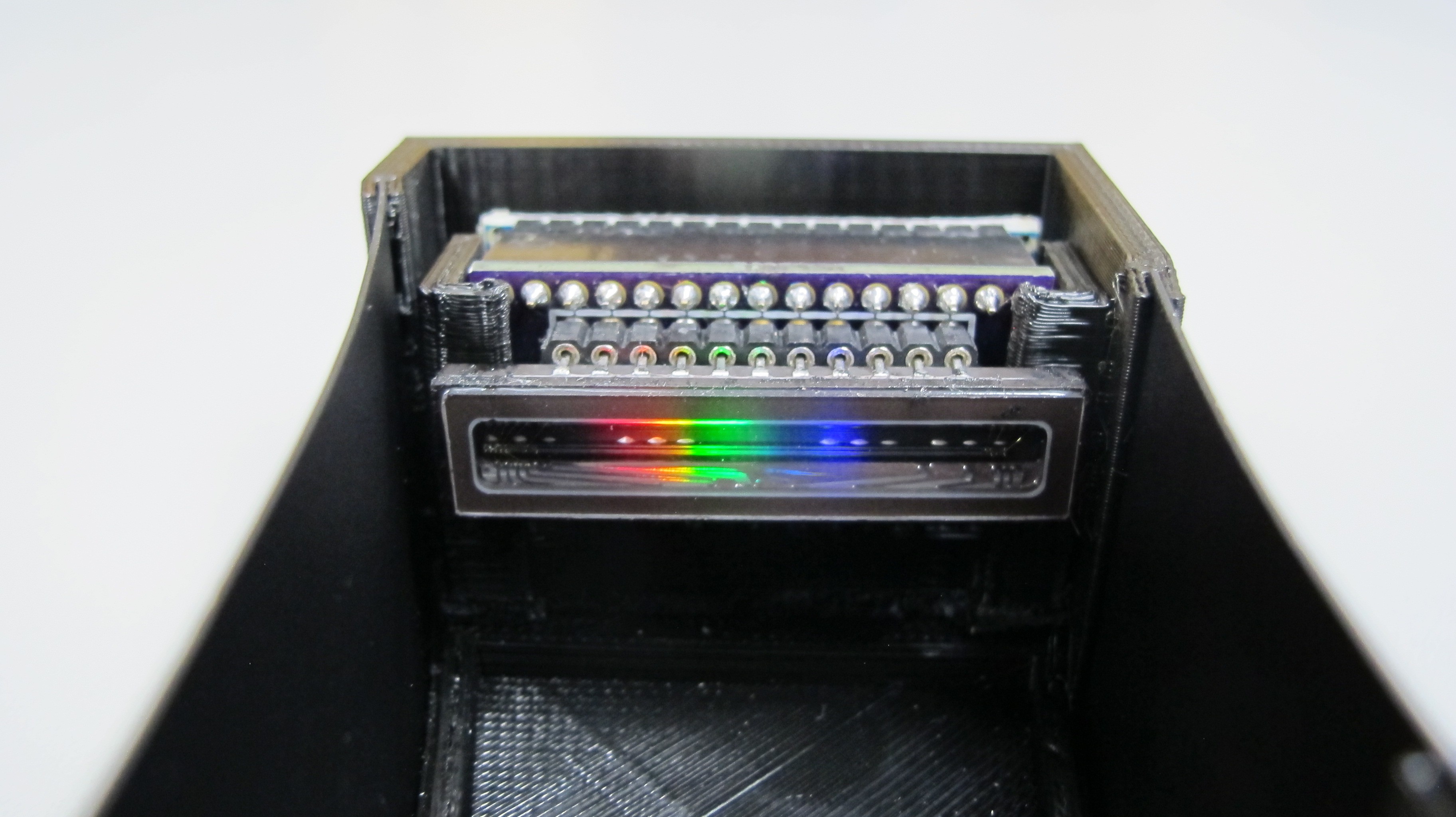
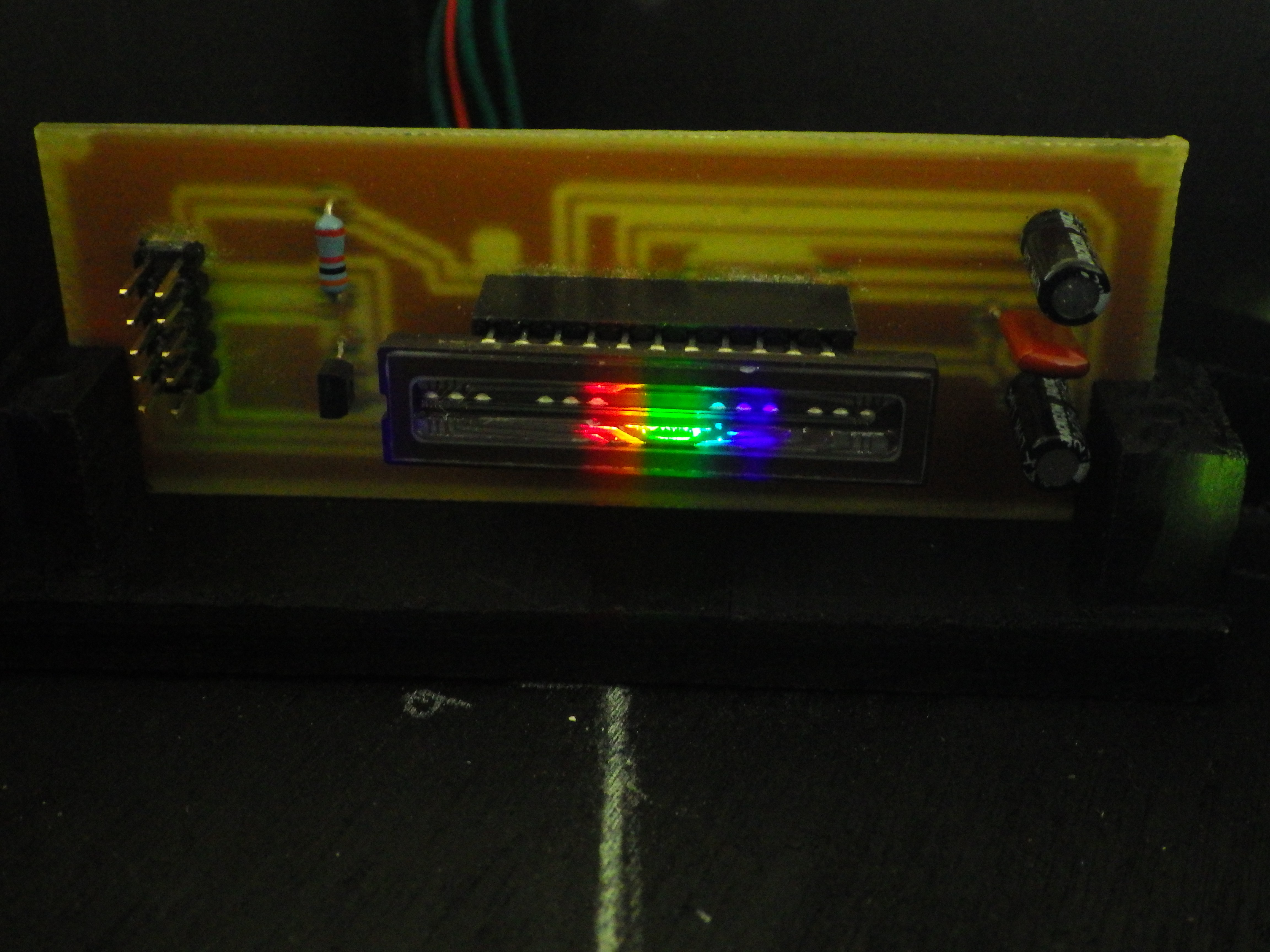
Close up of the CCD with diffracted white LED light.
![]()
Evolution of the CCD controller circuit Perfboard ---> Etched PCB ---> Arduino Nano CCD shield.
Close up shots of the etched CCD controller PCB.
![]()
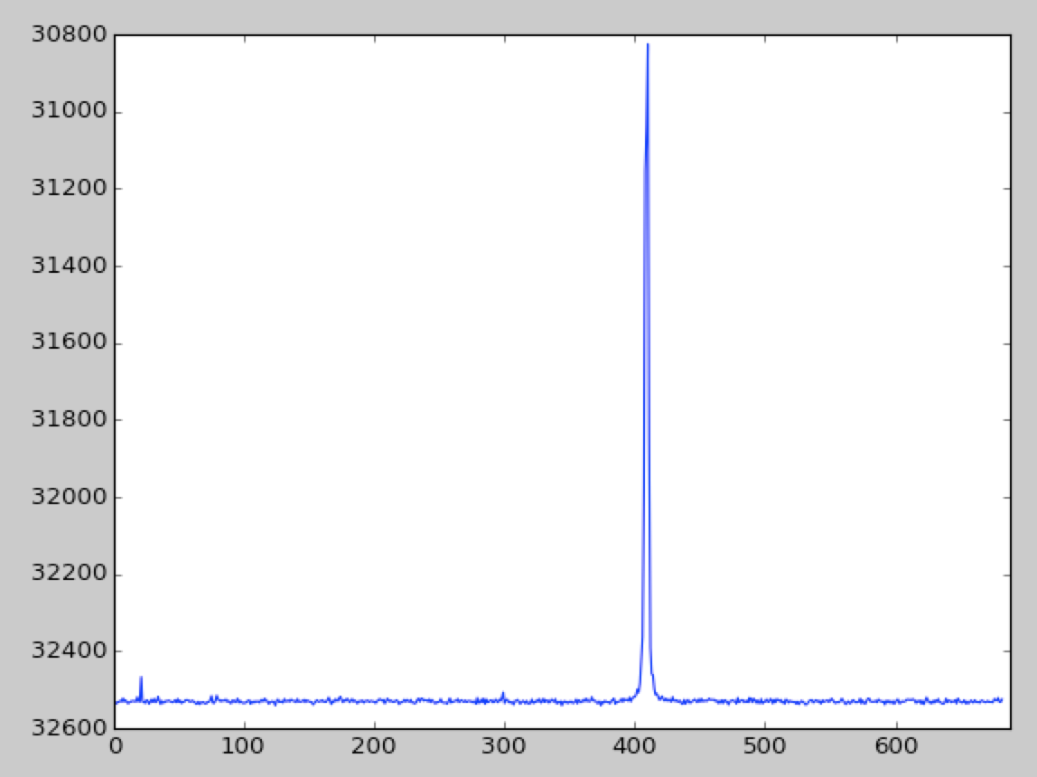
Red laser spectra
![]()
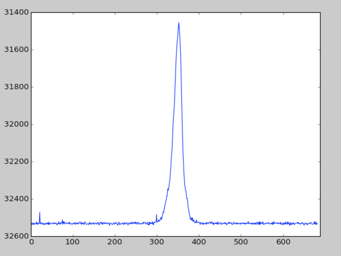
Green LED
![]() CFL Bulb
CFL Bulb
Handheld VNIR Spectrometer
A small portable spectrometer that can be used in the field to collect spectral data.
 Next up I need to design a cover and drill a hole to allow for USB connection to the CCD controller.
 Rectangular bundle
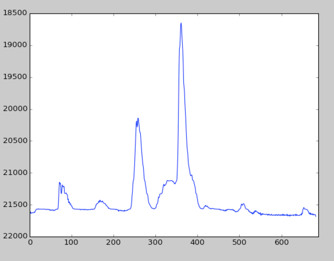 CFL Bulb