Close
0%
0%

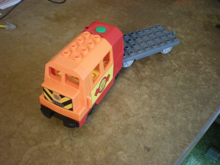
Remote controlled LEGO DUPLO locomotive

Modifying a LEGO DUPLO locomotive to be able to go forward as well as backward, have some lighting, and be remotely controlled.

Similar projects worth following

Desired features of the final locomotive are here:

  • go forward/backward, stop
  • front and rear lights
  • automatic shutdown (same as the original engine)
  • remote control
  • power & TX indication LEDs
  • RX indication LED
  • preserve the audio - power the original PCB on the engine; top button wired to MCU to allow using the engine without remote
    • short press - go forward
    • long press - go backward

  • 1 × Duplo Train Passenger Locomotive
  • 1 × attiny85 Microprocessors, Microcontrollers, DSPs / ARM, RISC-Based Microcontrollers
  • 2 × S8550 Discrete Semiconductors / Transistors, MOSFETs, FETs, IGBTs
  • 2 × S8050 Discrete Semiconductors / Transistors, MOSFETs, FETs, IGBTs
  • 4 × 220ohm resistor

View all 6 components

  • 2017-03-17 Conclusion

    Simon Fojtu03/17/2017 at 15:04 0 comments

    After half a year of thorough testing the locomotive seems to be working well. Nevertheless, there are some issues. I was at first worried that the voltage drop over the two transistors would make the locomotive significantly slower than the stock one. It is slightly slower but not by much. The actual battery voltage influences the maximal speed much more. I've left the original MCU inside to play the engine sounds and both the MCUs share the input signal from the button. But due to different button debouncing implementations it sometimes happens that the locomotive is moving without making any sound and vice versa. The engine drivers got accustomed to it and now pay no attention to a stopped locomotive making sounds as if it were actually driving. In future versions this should be addressed, e.g. by removing the original MCU and handling the sound in the additional one.

    I have some new ideas and plenty of old ones that might be implemented in next revisions of this project...

  • 2016-08-27 release version

    Simon Fojtu08/27/2016 at 11:27 0 comments

    After encountering many problems and reducing the specifications considerably, I've arrived at the release version, due to the deadline. But first things first.

    I've verified that the motor controller works on the breadboard, as described in the previous post. What was then my surprise, when the PCB version did not work! First I suspected I am switching the pins wrong, but multimeter asserted that the pins are fine, switching the transistors as expected, but only without the load connected. Once I connected the motor, it only buzzed a little and did not move. Only when I turned it with my hand did it start to rotate, but then the transistors got considerably hot. For a long time I was at a loss, not knowing how to debug it. I've even built the circuit again on a protoboard (thinking I got the PCB wrong), where it did not work either. Then I thought maybe the current running through the motor is too high for the transistors. After checking datasheets, calculating the motor current I tried to put a 4.7 ohm (at hand) resistor in series and voila! The motor started turning happily again. It seems the breadboard has some nonnegligible internal resistance in the connection, which is what baffled me for so long.

    With the motor problems out of the way, I continued with the remote control. I've found out that none of the IR transmitters and receivers were what I actually wanted. I've found and old IR receiver (TSOP38238), with which I played a little a long time ago, which required a 38kHz modulated IR light source. I've got some TV remotes, but I did not want to go and decode the messages without an oscilloscope or a logic analyzer, so I realized that the simplest message I need to transfer to the receiver is a long and short pulse, the same that are used to control the locomotive with a button. I've made a 555 based astable oscillator with a single button that powered the whole contraption, which would serve as the transmitter. Nevertheless, probably due to button debouncing or lack of thereof, I was not able to control the locomotive with it. So, due to the deadline I was forced to ommit the remote control.

    Last part was to fit the control board (attiny85 and h-bridge) inside the locomotive. I've measured the outline of the board and the position of the front axle correctly, so it would fit. But only until I tried to put the top cover over it. The front axle was locked and I wasn't able to properly seat the two parts together. After a little wirebending, PCB cutting and plastic chopping I arrived at a nice fit, closed the locomotive, screwed the screws, checked its functionality and now it awaits to be thoroughly tested by my sons.

    So, the goal was not met, but at least some improvement over the stock LEGO machine was made. I'll see how long it lasts and how will the boys like it and who knows, I might get back to it to add the remote control in the future. I've definitely learned many lessons in this small and easy project.

  • 2016-07-20 motor control

    Simon Fojtu08/01/2016 at 19:22 0 comments

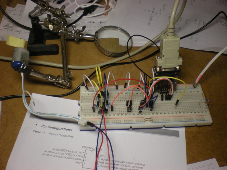
    I've made plenty of mistakes in the design of the receiver pcb. I've forgotten a pull-up resistor on RESET signal, but it seems it is not entirely necessary, since on a breadboard the attiny85 is running fine. I've forgotten the clamping diodes on the H-bridge, but again the breadboard version without them is running happily (it seems). Nevertheless, the diodes can be bodged to the transistors even without own footprints on the pcb. Hardware debouncing of the button is missing as well. It is not present on the original circuit so either the type of button used is not prone to bouncing or it is solved in software. In my breadboarding experiments it seems that a single 10uF electrolytic capacitor (the value and type were the first on hand) between the pin and ground get rid of all bouncing. If only the pin (PB2) was not SCK required for programming the chip. It seems the MCU wants its clock nice and straight and not filtered out :)

    All in all it is a lovely endeavour and the breadboarded receiver (or rather a controller, since there is no signal to be received yet) is working well with all the interrupts and correct sleep modes. Short press makes the motor turn in one direction, long in the other, as desired.

    Also, I've tried to use C++ in an embedded system, works like a charm.

  • ​ 2016-07-19 RC update

    Simon Fojtu08/01/2016 at 19:20 0 comments

    Since I've got mainly evenings for this project, I've decided to send the receiver PCB to fab (oshpark), expected arrival well before deadline at 28. 8.

    The radio modules arrived. While testing the motor driver and radio receiver, it is obvious that the motor severely interferes with the simple communication at 433MHz. I've kind of expected that and thought it could be solved in software by using some encoding, but without an oscilloscope it would be hard to make it robust. Thus I've ordered some IR receivers, which should not be bothered by any EM interference. The main goal is to make the locomotive go forward and backward, remote control is a bonus to implement if there is time.

  • 2016-07-10 Reverse engineering the original circuitry

    Simon Fojtu08/01/2016 at 19:18 0 comments

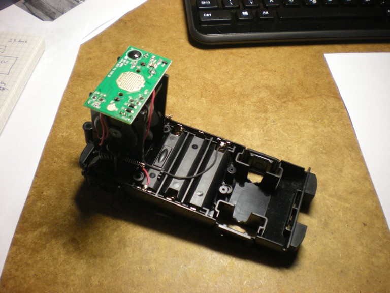
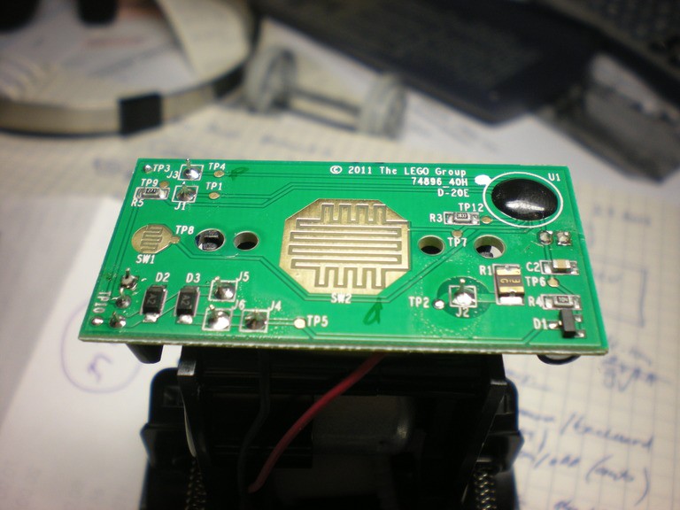
    There are two ways to determine the current passing through the motor. I can measure it, which requires de-soldering the wires to the motor, or I can determine what components are used in the original circuit and trust the designer that the parts are well sized.


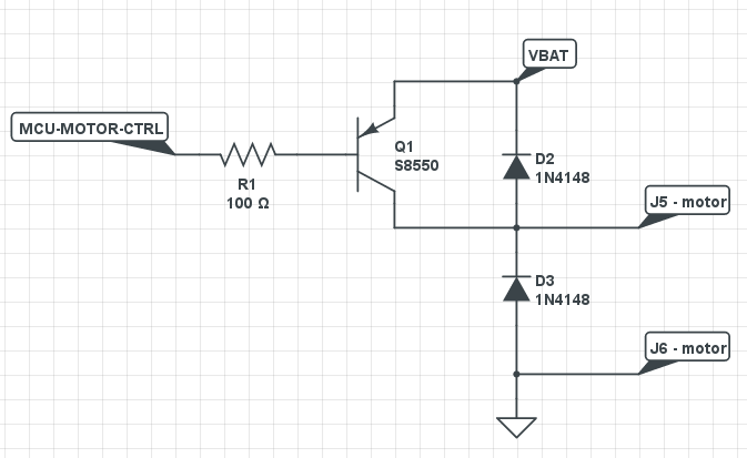
    I've started with the latter and found out that the motor is controlled by a single PNP transistor S8550.

    This is the motor driver circuit.

    Since the locomotive goes only in one direction a single transistor is sufficient. The positive battery terminal is not 100% correct, it is wired through a resistor R1, but I'm not sure about its use or value (also note that the R1 label in the schematics should be R5).

  • 2016-07-01 LEGO bricks + RC

    Simon Fojtu08/01/2016 at 18:38 0 comments

    LEGO bricks

    I've got the LEGO bricks from The_Duplo_Store via bricklink.com.

    • [Used] Dark Bluish GrayDuplo, Train Base 4 x 8 with Light Bluish Gray Train Wheels and Moveable Hook
    • [Used] OrangeDuplo, Train Locomotive Cabin Roof 2 x 4 Studs, 4 Medium Windows
    • [Used] OrangeDuplo, Train Locomotive Front with Silver Headlight, 10508 and V Stripes Pattern
    • [Used] RedDuplo, Train Passenger Locomotive Base with Black Battery Compartment, Light Bluish Gray Wheels
    • [Used] YellowDuplo, Train Cab / Tender Base with Bottom Tubes with Box and Arrows Pattern on Both Sides

    The bricks required thorough cleanup, but hey, batteries included..

    Radio control

    I've bought a 433MHz transmitter + receiver modules (http://www.ebay.com/itm/380717845396). This is the first time I'm dealing with RF so troubles are to be expected, but I'm not rolling my own transmitter or receiver so I should be fine, right?

View all 6 project logs

Enjoy this project?

Share

Discussions

Similar Projects

Does this project spark your interest?

Become a member to follow this project and never miss any updates